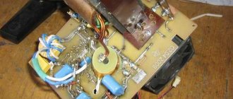
A DIY welding inverter made from a computer power supply is becoming increasingly popular among both professionals and amateur welders. The advantages of such devices are that they are comfortable and lightweight.
Welding inverter device.
The use of an inverter power source allows you to qualitatively improve the characteristics of the welding arc, reduce the size of the power transformer and thereby lighten the weight of the device, makes it possible to make adjustments smoother and reduce spatter during welding. The disadvantage of an inverter-type welding machine is its significantly higher price than its transformer counterpart.
In order not to overpay large sums of money in stores for welding, you can make a welding inverter with your own hands. To do this, you need a working computer power supply, several electrical measuring instruments, tools, basic knowledge and practical skills in electrical work. It would also be useful to acquire relevant literature.
If you are not confident in your abilities, then you should go to the store for a ready-made welding machine, otherwise, with the slightest mistake during the assembly process, there is a risk of getting an electric shock or burning all the electrical wiring. But if you have experience in assembling circuits, rewinding transformers and creating electrical appliances with your own hands, you can safely begin the assembly.
Operating principle of inverter welding
Schematic diagram of the inverter.
The welding inverter consists of a power transformer that reduces the network voltage, stabilizer chokes that reduce current ripple, and an electrical circuit block. MOSFET or IGBT transistors can be used for the circuits.
The principle of operation of the inverter is as follows: alternating current from the network is sent to the rectifier, after which the power module converts direct current into alternating current with increasing frequency. Next, the current enters the high-frequency transformer, and the output from it is the welding arc current.
General procedure for diagnosing welding inverters
Before repairing the device, you should check the functionality of the cooling system. Cooling radiators clogged with dust remove heat from the power elements much worse, which means the fins should be completely cleaned of dust and other debris.
Repair of inverter welding machines should begin with diagnosing the input rectifier.
To fully check this node you should:
- disassemble the module;
- remove the radiator;
- remove the diode bridge;
- ring the contacts of the diode bridge.
If no problems with the diode bridge are identified, you should move on to the next module - the output rectifier.
Typical inverter faults.
The functionality of the output rectifier is checked using the following algorithm:
- disassemble the module;
- unsolder the diode assemblies;
- ring the diodes.
In addition to diodes, the output rectifier circuit contains radiators that should be installed back after repairing the module.
After examining the output rectifier, you should proceed to diagnosing the key module.
This inverter module consists of:
- four groups of transistors;
- key control boards;
- smoothing rectifiers.
The procedure for examining the key module is as follows:
- Checking transistors. As a rule, a faulty element is clearly visible to the naked eye. If this is not the case, then you should check the sequence of all available transistors with a tester.
- If measurements with a tester do not produce results, you need to diagnose the transistor assemblies using an avometer, measuring the resistance.
- If all components appear to be in good working order, all transistors should be unsoldered one by one. This diagnostic method is suitable if there is a short circuit on the board.
If the transistor converters of the control unit are fully operational, you need to inspect the key control board. To carry out such diagnostics, you should prepare an oscilloscope.
Most inverter problems can be diagnosed by carefully inspecting the electronic components. If defective parts are identified, you should immediately remove them and replace them with similar characteristics.
Tools required to make an inverter
To assemble a welding inverter from a power supply with your own hands, you will need the following tools:
TL494 voltage feedback circuit in a computer power supply.
- soldering iron;
- screwdrivers with different tips;
- pliers;
- wire cutters;
- drill or screwdriver;
- crocodiles;
- wires of the required cross-section;
- tester;
- multimeter;
- consumables (wires, solder for soldering, electrical tape, screws and others).
To create a welding machine from a computer power supply, you need materials to create a printed circuit board, getinaks, and spare parts. To reduce the amount of work, you should go to the store for ready-made electrode holders. However, you can make them yourself by soldering crocodiles to wires of the required diameter. It is important to observe polarity when doing this work.
Repair of inverter power unit
Electrical circuit of a welding inverter.
To repair the inverter power unit, the following tools may be required:
- pliers;
- two soldering irons with a power of 40 and 100 watts;
- screwdrivers of various types;
- wrenches and socket wrenches;
- knife;
- wire cutters;
- tester for electrical network;
- oscilloscope;
- calipers;
- micrometer.
The most typical breakdown of the power unit of a welding inverter is the failure of a powerful transistor. In most cases, a damaged transistor can be identified visually: it has defects, burnouts or deformation. Repairing an inverter if a defective transistor is detected is reduced to replacing it.
There are many cases when a transistor breakdown is only a consequence and not a cause. With this development of events, replacing the transistor assembly may not give a visible effect.
If, after replacing the transistor, the functionality of the device has not been restored, then it makes sense to move on to the next step, namely diagnosing and replacing elements from the diode bridge.
Before repairing the diode bridge, you should check the functionality of all elements. This can be done by alternately measuring the resistance on the legs of the elements. If the resistance between the multimeter probes located on the diode legs is zero or infinity, then this element should be replaced.
New transistors or diodes should be selected from analogs with similar characteristics. As a rule, analogues of the vast majority of models of electronic components are available for sale.
Components of a welding inverter.
When repairing the inverter power unit, you should adhere to the following rules:
- Do not use an electrical appliance with an open insulating casing.
- Diagnostics and replacement of all electronic components must be carried out on a de-energized welding machine.
- It is best to remove accumulated dust and debris from the device using a compressor or a can of compressed air.
- Cleaning the board from sticky traces and used flux should be done using plastic-neutral solvents. It is recommended to use a special brush for cleaning electronic components.
- A working device should be stored in a disconnected state and with the casing completely closed.
The procedure for assembling the welding machine
First of all, to create a welding machine from a computer power supply, you need to remove the power source from the computer case and disassemble it. The main elements that can be used from it are a few spare parts, a fan and standard case plates. It is important to take into account the cooling operating mode. This determines what elements need to be added to ensure the necessary ventilation.
Diagram of a transformer with primary and secondary windings.
The operation of a standard fan, which will cool the future welding machine from a computer unit, must be tested in several modes. This check will ensure the functionality of the element. To prevent the welding machine from overheating during operation, you can install an additional, more powerful cooling source.
To control the required temperature, a thermocouple should be installed. The optimal temperature for operating the welding machine should not exceed 72-75°C.
But first of all, you should install a handle of the required size on the welding machine from a computer power supply for carrying and ease of use. The handle is installed on the top panel of the block using screws.
It is important to choose screws that are optimal in length, otherwise too large ones may affect the internal circuit, which is unacceptable. At this stage of work, you should worry about good ventilation of the device. The placement of elements inside the power supply is very dense, so a large number of through holes should be arranged in it in advance. They are performed with a drill or screwdriver.
Next, you can use multiple transformers to create an inverter circuit. Typically, 3 transformers such as ETD59, E20 and Kx20x10x5 are chosen. You can find them in almost any radio electronics store. And if you already have experience creating transformers yourself, then it’s easier to do them yourself, focusing on the number of turns and the performance characteristics of the transformers. Finding such information on the Internet will not be difficult. You may need a current transformer K17x6x5.
Methods for connecting a welding inverter.
It is best to make homemade transformers from getinax coils; the winding will be enamel wire with a cross-section of 1.5 or 2 mm. You can use 0.3x40 mm copper sheet, after wrapping it in durable paper. Thermal paper from a cash register (0.05 mm) is suitable; it is durable and does not tear so much. The crimping should be done from wooden blocks, after which the entire structure should be filled with “epoxy” or varnished.
When creating a welding machine from a computer unit, you can use a transformer from a microwave oven or old monitors, not forgetting to change the number of turns of the winding. For this work, it would be useful to use electrical engineering literature.
As a radiator, you can use PIV, previously cut into 3 parts, or other radiators from old computers. You can purchase them in specialized stores that disassemble and upgrade computers. Such options will pleasantly save time and effort in searching for suitable cooling.
To create a device from a computer power supply, you must use a single-cycle forward quasi-bridge, or “oblique bridge”. This element is one of the main ones in the operation of the welding machine, so it is better not to save on it, but to purchase a new one in the store.
Printed circuit boards can be downloaded on the Internet. This will make recreating the circuit much easier. In the process of creating the board, you will need capacitors, 12-14 pieces, 0.15 microns, 630 volts. They are necessary to block resonant current surges from the transformer. Also, to make such a device from a computer power supply, you will need capacitors C15 or C16 with the brand K78-2 or SVV-81. Transistors and output diodes should be installed on radiators without using additional gaskets.
During operation, you must constantly use a tester and a multimeter to avoid errors and to assemble the circuit faster.
Electrical circuit of a semi-automatic welding machine.
After manufacturing all the necessary parts, they should be placed in the housing and then routed. The temperature on the thermocouple should be set to 70°C: this will protect the entire structure from overheating. After assembly, the welding machine from a computer unit must be pre-tested. Otherwise, if you make a mistake during assembly, you can burn all the main elements, or even get an electric shock.
On the front side, two contact holders and several current regulators should be installed. The device switch in this design will be a standard computer unit toggle switch. The body of the finished device after assembly requires additional strengthening.
DIY welding inverter
We present to your attention a diagram of a welding inverter that you can assemble with your own hands. Maximum current consumption is 32 amperes, 220 volts. The welding current is about 250 amperes, which allows you to easily weld with a 5-piece electrode, an arc length of 1 cm, which passes more than 1 cm into low-temperature plasma. The efficiency of the source is at the level of store-bought ones, and maybe better (meaning inverter ones).
Figure 1 shows a diagram of the power supply for welding.
Fig. 1 Schematic diagram of the power supply
The transformer is wound on ferrite Sh7x7 or 8x8 The primary has 100 turns of PEV 0.3mm wire Secondary 2 has 15 turns of PEV 1mm wire Secondary 3 has 15 turns of PEV 0.2mm Secondary 4 and 5 each have 20 turns of PEV 0.35mm wire All The windings must be wound across the entire width of the frame; this gives a noticeably more stable voltage.
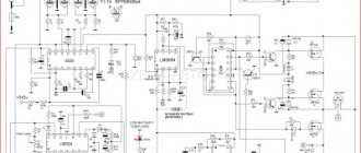
Fig.2 Schematic diagram of a welding inverter
Figure 2 shows a diagram of the welder. The frequency is 41 kHz, but you can try 55 kHz. The transformer at 55 kHz is then 9 turns by 3 turns, to increase the PV of the transformer.
41kHz transformer - two sets Ш20х28 2000nm, gap 0.05mm, newspaper gasket, 12vit x 4vit, 10kv mm x 30kv mm, copper tape (tin) in paper. The transformer windings are made of copper sheet 0.25 mm thick and 40 mm wide, wrapped in cash register paper for insulation. The secondary is made of three layers of tin (sandwich) separated from each other by fluoroplastic tape, for insulation between themselves, for better conductivity of high-frequency currents, the contact ends of the secondary at the output of the transformer are soldered together.
Inductor L2 is wound on a Ш20x28 core, ferrite 2000nm, 5 turns, 25 sq.mm, gap 0.15 - 0.5mm (two layers of paper from the printer). Current transformer - current sensor two rings K30x18x7 primary wire threaded through the ring, secondary 85 turns of wire 0.5 mm thick.
Welding assembly
Winding the transformer
Winding the transformer must be done using copper sheet 0.3mm thick and 40mm wide, it must be wrapped in thermal paper from a cash register 0.05mm thick, this paper is durable and does not tear as much as usual when winding a transformer.
You tell me, why not wind it with an ordinary thick wire, but it’s not possible because this transformer operates on high-frequency currents and these currents are displaced onto the surface of the conductor and the middle of the thick wire is not used, which leads to heating, this phenomenon is called the Skin effect!
And you have to fight it, you just need to make a conductor with a large surface, so thin copper sheet has this, it has a large surface along which current flows, and the secondary winding should consist of a sandwich of three copper tapes separated by fluoroplastic film, it is thinner and all these are wrapped layers in thermal paper. This paper has the property of darkening when heated, we don’t need this and it’s bad, it won’t do anything, let the main thing remain that it doesn’t tear.
You can wind the windings with PEV wire with a cross-section of 0.5...0.7 mm consisting of several dozen cores, but this is worse, since the wires are round and are connected to each other with air gaps, which slow down heat transfer and have a smaller total cross-sectional area of the wires combined compared to tin by 30 %, which can fit into the ferrite core window.
It is not the ferrite that heats up the transformer, but the winding, so you need to follow these recommendations.
The transformer and the entire structure must be blown inside the housing by a fan of 220 volts 0.13 amperes or more.
Design
To cool all powerful components, it is good to use radiators with fans from old Pentium 4 and Athlon 64 computers. I got these radiators from a computer store doing upgrades, for only $3...4 apiece.
The power oblique bridge must be made on two such radiators, the upper part of the bridge on one, the lower part on the other. Screw bridge diodes HFA30 and HFA25 onto these radiators through a mica spacer. IRG4PC50W must be screwed without mica through KTP8 heat-conducting paste.
The terminals of the diodes and transistors need to be screwed towards each other on both radiators, and between the terminals and the two radiators, insert a board connecting the 300-volt power circuit to the bridge parts.
The diagram does not indicate the need to solder 12...14 pieces of 0.15 micron 630 volt capacitors to this board into a 300V power supply. This is necessary so that the transformer emissions go into the power circuit, eliminating the resonant current surges of the power switches from the transformer.
The rest of the bridge is connected to each other by hanging installation of conductors of short length.
The diagram also shows snubbers, they have capacitors C15 C16, they should be brand K78-2 or SVV-81. You can’t put any garbage there, since snubbers play an important role: first , they dampen the resonant emissions of the transformer; second , they significantly reduce IGBT losses when turned off, since IGBTs open quickly, but close much more slowly, and during closing, capacitance C15 and C16 are charged through the VD32 VD31 diode is longer than the closing time of the IGBT, that is, this snubber intercepts all the power, preventing heat from being released on the IGBT switch three times than it would be without it. When the IGBTs open quickly, the snubbers are smoothly discharged through resistors R24 R25 and the main power is released on these resistors.
Settings
Apply power to the 15-volt PWM and at least one fan to discharge capacitance C6, which controls the relay response time.
Relay K1 is needed to close resistor R11 after capacitors C9...12 are charged through resistor R11, which reduces the current surge when the welding machine is turned on to a 220-volt network.
Without direct resistor R11, when turned on, there would be a large BAC while charging a 3000 μm 400V capacitance, which is why this measure is needed.
Check the operation of the relay closing resistor R11 2...10 seconds after power is applied to the PWM board.
Check the PWM board for the presence of rectangular pulses going to the HCPL3120 optocouplers after both relays K1 and K2 are activated.
The width of the pulses should be relative to the zero pause 44% zero 66%
Check the drivers on optocouplers and amplifiers that drive a rectangular signal with an amplitude of 15 volts and make sure that the voltage on the IGBT gates does not exceed 16 volts.
Apply 15 Volt power to the bridge to check its operation and ensure that the bridge is manufactured correctly.
The current consumption should not exceed 100mA at idle.
Verify the correct phrasing of the windings of the power transformer and current transformer using a two-beam oscilloscope.
One beam of the oscilloscope is on the primary, the second on the secondary, so that the phases of the pulses are the same, the only difference is in the voltage of the windings.
Apply power to the bridge from power capacitors C9...C12 through a 220 volt 150..200 watt light bulb, having previously set the PWM frequency to 55 kHz, connect an oscilloscope to the collector-emitter of the lower IGBT transistor, look at the signal shape so that there are no voltage surges above 330 volts as usual.
Start lowering the PWM clock frequency until a small bend appears on the lower IGBT switch indicating oversaturation of the transformer, write down this frequency at which the bend occurred, divide it by 2 and add the result to the oversaturation frequency, for example, divide 30 kHz oversaturation by 2 = 15 and 30 + 15 = 45 , 45 this is the operating frequency of the transformer and PWM.
The current consumption of the bridge should be about 150 mA and the light bulb should barely glow; if it glows very brightly, this indicates a breakdown of the transformer windings or an incorrectly assembled bridge.
Connect a welding wire at least 2 meters long to the output to create additional output inductance.
Apply power to the bridge through a 2200-watt kettle, and set the current on the light bulb to PWM at least R3 closer to resistor R5, close the welding output, check the voltage on the lower switch of the bridge so that it is no more than 360 volts according to the oscilloscope, and there should be no noise from the transformer. If there is one, make sure that the transformer-current sensor is correctly phased, pass the wire in the opposite direction through the ring.
If the noise remains, then you need to place the PWM board and optocoupler drivers away from sources of interference, mainly the power transformer and inductor L2 and power conductors.
Even when assembling the bridge, the drivers must be installed next to the radiators of the bridge above the IGBT transistors and no closer to the resistors R24 R25 by 3 centimeters. The driver output and IGBT gate connections must be short. The conductors going from the PWM to the optocouplers should not pass near sources of interference and should be as short as possible.
All signal wires from the current transformer and going to the optocouplers from the PWM should be twisted to reduce noise and should be as short as possible.
Next, we begin to increase the welding current using resistor R3 closer to resistor R4, the welding output is closed on the lower IGBT switch, the pulse width increases slightly, which indicates PWM operation. More current means more width, less current means less width.
the IGBT will fail .
Add current and listen, watch the oscilloscope for excess voltage of the lower key, so that it does not exceed 500 volts, a maximum of 550 volts in the surge, but usually 340 volts.
Reach the current where the width suddenly becomes maximum, indicating that the kettle cannot provide maximum current.
That's it, now we go straight without a kettle from minimum to maximum, watch the oscilloscope and listen so that it is quiet. Reach the maximum current, the width should increase, emissions are normal, no more than 340 volts usually.
Start cooking for 10 seconds at the beginning. We check the radiators, then 20 seconds, also cold and 1 minute the transformer is warm, burn 2 long electrodes 4mm transformer is bitter
The radiators of the 150ebu02 diodes noticeably warmed up after three electrodes, it’s already difficult to cook, a person gets tired, although he cooks great, the transformer is hot, and no one cooks anyway. The fan, after 2 minutes, brings the transformer to a warm state and you can cook it again until it becomes puffy.
Below you can download printed circuit boards in LAY format and other files
Evgeny Rodikov (evgen100777 [dog] rambler.ru). If you have any questions when assembling the welder, write to E-Mail.
List of radioelements
| Designation | Type | Denomination | Quantity | Note | Shop | My notepad |
| power unit | ||||||
| Linear regulator | LM78L15 | 2 | Search in the Otron store | To notepad | ||
| AC/DC converter | TOP224Y | 1 | Search in the Otron store | To notepad | ||
| Voltage reference IC | TL431 | 1 | Search in the Otron store | To notepad | ||
| Rectifier diode | BYV26C | 1 | Search in the Otron store | To notepad | ||
| Rectifier diode | HER307 | 2 | Search in the Otron store | To notepad | ||
| Rectifier diode | 1N4148 | 1 | Search in the Otron store | To notepad | ||
| Schottky diode | MBR20100CT | 1 | Search in the Otron store | To notepad | ||
| Protection diode | P6KE200A | 1 | Search in the Otron store | To notepad | ||
| Diode bridge | KBPC3510 | 1 | Search in the Otron store | To notepad | ||
| Optocoupler | PC817 | 1 | Search in the Otron store | To notepad | ||
| C1, C2 | Electrolytic capacitor | 10uF 450V | 2 | Search in the Otron store | To notepad | |
| Electrolytic capacitor | 100uF 100V | 2 | Search in the Otron store | To notepad | ||
| Electrolytic capacitor | 470uF 400V | 6 | Search in the Otron store | To notepad | ||
| Electrolytic capacitor | 50uF 25V | 1 | Search in the Otron store | To notepad | ||
| C4, C6, C8 | Capacitor | 0.1uF | 3 | Search in the Otron store | To notepad | |
| C5 | Capacitor | 1nF 1000V | 1 | Search in the Otron store | To notepad | |
| C7 | Electrolytic capacitor | 1000uF 25V | 1 | Search in the Otron store | To notepad | |
| Capacitor | 510 pF | 2 | Search in the Otron store | To notepad | ||
| C13, C14 | Electrolytic capacitor | 10 µF | 2 | Search in the Otron store | To notepad | |
| VDS1 | Diode bridge | 600V 2A | 1 | Search in the Otron store | To notepad | |
| NTC1 | Thermistor | 10 ohm | 1 | Search in the Otron store | To notepad | |
| R1 | Resistor | 47 kOhm | 1 | Search in the Otron store | To notepad | |
| R2 | Resistor | 510 Ohm | 1 | Search in the Otron store | To notepad | |
| R3 | Resistor | 200 Ohm | 1 | Search in the Otron store | To notepad | |
| R4 | Resistor | 10 kOhm | 1 | Search in the Otron store | To notepad | |
| Resistor | 6.2 Ohm | 1 | Search in the Otron store | To notepad | ||
| Resistor | 30Ohm 5W | 2 | Search in the Otron store | To notepad | ||
| Welding inverter | ||||||
| PWM controller | UC3845 | 1 | Search in the Otron store | To notepad | ||
| VT1 | MOSFET transistor | IRF120 | 1 | Search in the Otron store | To notepad | |
| VD1 | Rectifier diode | 1N4148 | 1 | Search in the Otron store | To notepad | |
| VD2, VD3 | Schottky diode | 1N5819 | 2 | Search in the Otron store | To notepad | |
| VD4 | Zener diode | 1N4739A | 1 | 9V | Search in the Otron store | To notepad |
| VD5-VD7 | Rectifier diode | 1N4007 | 3 | To reduce voltage | Search in the Otron store | To notepad |
| VD8 | Diode bridge | KBPC3510 | 2 | Search in the Otron store | To notepad | |
| C1 | Capacitor | 22 nF | 1 | Search in the Otron store | To notepad | |
| C2, C4, C8 | Capacitor | 0.1 µF | 3 | Search in the Otron store | To notepad | |
| C3 | Capacitor | 4.7 nF | 1 | Search in the Otron store | To notepad | |
| C5 | Capacitor | 2.2 nF | 1 | Search in the Otron store | To notepad | |
| C6 | Electrolytic capacitor | 22 µF | 1 | Search in the Otron store | To notepad | |
| C7 | Electrolytic capacitor | 200 µF | 1 | Search in the Otron store | To notepad | |
| C9-C12 | Electrolytic capacitor | 3000uF 400V | 4 | Search in the Otron store | To notepad | |
| R1, R2 | Resistor | 33 kOhm | 2 | Search in the Otron store | To notepad | |
| R4 | Resistor | 510 Ohm | 1 | Search in the Otron store | To notepad | |
| R5 | Resistor | 1.3 kOhm | 1 | Search in the Otron store | To notepad | |
| R7 | Resistor | 150 Ohm | 1 | Search in the Otron store | To notepad | |
| R8 | Resistor | 1Ohm 1Watt | 1 | Search in the Otron store | To notepad | |
| R9 | Resistor | 2 MOhm | 1 | Search in the Otron store | To notepad | |
| R10 | Resistor | 1.5 kOhm | 1 | Search in the Otron store | To notepad | |
| R11 | Resistor | 25Ohm 40Watt | 1 | Search in the Otron store | To notepad | |
| R3 | Trimmer resistor | 2.2 kOhm | 1 | Search in the Otron store | To notepad | |
| Trimmer resistor | 10 kOhm | 1 | Search in the Otron store | To notepad | ||
| K1 | Relay | 12V 40A | 1 | Search in the Otron store | To notepad | |
| K2 | Relay | RES-49 | 1 | Search in the Otron store | To notepad | |
| Q6-Q11 | IGBT transistor | IRG4PC50W | 6 | Search in the Otron store | To notepad | |
| MOSFET transistor | IRF5305 | 8 | Search in the Otron store | To notepad | ||
| D2, D3 | Schottky diode | 1N5819 | 2 | Search in the Otron store | To notepad | |
| VD17, VD18 | Rectifier diode | VS-HFA30PA60CPBF | 2 | Search in the Otron store | To notepad | |
| VD19-VD22 | Rectifier diode | VS-150EBU02 | 4 | Search in the Otron store | To notepad | |
| VD31, VD32 | Rectifier diode | VS-HFA25PB60PBF | 2 | Search in the Otron store | To notepad | |
| VD36-VD41 | Zener diode | 1N4744A | 12 | Search in the Otron store | To notepad | |
| Optocoupler | HCPL-3120 | 2 | Search in the Otron store | To notepad | ||
| C13, C21 | Electrolytic capacitor | 10 µF | 2 | Search in the Otron store | To notepad | |
| C15-C18 | Capacitor | 6.8 nF | 4 | K78-2 or SVV-81 | Search in the Otron store | To notepad |
| C20, C22 | Electrolytic capacitor | 47uF 25V | 2 | Search in the Otron store | To notepad | |
| L2 | Inductor | 35 µH | 1 | Search in the Otron store | To notepad | |
| R12, R13, R50, R54 | Resistor | 1 kOhm | 4 | Search in the Otron store | To notepad | |
| R14, R15 | Resistor | 1.5 kOhm | 2 | Search in the Otron store | To notepad | |
| R17, R51 | Resistor | 10 ohm | 2 | Search in the Otron store | To notepad | |
| R24, R25 | Resistor | 30Ohm 20Watt | 2 | Search in the Otron store | To notepad | |
| R26 | Resistor | 2.2 kOhm | 1 | Search in the Otron store | To notepad | |
| R27, R28 | Resistor | 5Ohm 5Watt | 2 | Search in the Otron store | To notepad | |
| R36, R46-R48, R52, R42-R44 | Resistor | 5 ohm | 8 | Search in the Otron store | To notepad | |
| R45, R53 | Resistor | 1.5 Ohm | 2 | Search in the Otron store | To notepad | |
| Add all | ||||||
Attached files:
- welding.rar (495 Kb)
Tags:
- Sprint-Layout
- Welding
Advantages of a welding machine from a computer power supply
A homemade welding machine will be small and light. It is perfect for home welding; it is convenient to weld with two or three electrodes, without experiencing problems with “flashing lights” and without worrying about the electrical wiring. The power supply for such a welding machine can be any household outlet, and during operation such a device will practically not spark.
By making a welding inverter with your own hands, you can significantly save on purchasing a new device, but this approach will require a significant investment of both effort and time. After assembling the finished sample, you can try to make your own changes to the welding machine from the computer unit and its circuit, to make lightweight models of greater power. And by making such devices for friends to order, you can provide yourself with a good additional income.
Read also: How to tighten a belt with two rings
Common causes of breakdowns
Do-it-yourself repair of welding inverters is possible for the following faults:
- Unstable welding arc. In most cases, such a malfunction is associated with an incorrect choice of the inverter operating mode. To select the optimal current strength, you can follow the rule: 20 to 40 amperes of current should be supplied per 1 millimeter of electrode diameter.
- The appearance of forces when separating the electrode from the metal. A typical malfunction that occurs due to low voltage coming to the electrodes. The simplest way to solve this problem is to clean the contacts of the power supply from oxides and carbon deposits.
- No welding jet. If there is no power when you turn the toggle switch to turn on the device, you should check the voltage in the electrical network.
- Inverter shutdown during prolonged operation. As a rule, such behavior of the inverter can be associated with overheating. The way out is simple: let the device cool down and start working again after 30 minutes.
Scheme of an inverter welding machine.
When diagnosing a welding machine, the following faults may be detected:
- arising as a result of incorrect choice of welding mode;
- arising as a result of failure of electronic components of equipment.
In any of the above cases, you can repair the welding inverter yourself.
Most malfunctions of this welding machine unit are associated with the failure of electronic components.
The main types of electronic circuit faults are presented:
- Moisture entering the inverter housing. Oxidation of conductive paths due to moisture ingress can cause a breakdown in contact between the main components of the device.
- Formation of a large amount of dust on the main working elements. Excessive dust contamination of inverter elements can disrupt the natural circulation of air in the housing and lead to overheating of electronic components.
- Selecting the wrong operating mode for the inverter, resulting in overheating of electronic components. Inverter failure due to overheating of electronic components is one of the most common failures.
In addition, the device’s inoperability may be due to the failure of one of the modules.
Most inverters use:
- input rectifier;
- output rectifier;
- key control unit;
- cooling system.
Do-it-yourself inverter welding is very simple
Inverter welding is a modern device that is widely popular due to the light weight of the device and its dimensions. The inverter mechanism is based on the use of field-effect transistors and power switches. To become the owner of a welding machine, you can visit any tool store and acquire such a useful thing. But there is a much more economical way, which is due to the creation of inverter welding with your own hands. It is the second method that we will pay attention to in this material and consider how to do welding at home, what is needed for this and what the diagrams look like.
Features of the inverter operation
An inverter-type welding machine is nothing more than a power supply, the one that is now used in modern computers. What is the operation of the inverter based on? The following picture of electrical energy conversion is observed in the inverter:
1) The voltage consumed from the network is converted to DC.
2) Current with a constant sinusoid is converted into alternating current with a high frequency.
3) The voltage value decreases.
4) The current is rectified while maintaining the required frequency.
A list of such electrical circuit transformations is necessary in order to be able to reduce the weight of the device and its overall dimensions. After all, as you know, old welding machines, the principle of which is based on reducing the voltage and increasing the current on the secondary winding of the transformer. As a result, due to the high current value, the possibility of arc welding of metals is observed. In order for the current to increase and the voltage to decrease, the number of turns on the secondary winding decreases, but the cross-section of the conductor increases. As a result, you can notice that a transformer-type welding machine not only has significant dimensions, but also a decent weight.
To solve the problem, an option was proposed for implementing a welding machine using an inverter circuit. The principle of the inverter is based on increasing the frequency of the current to 60 or even 80 kHz, thereby reducing the weight and dimensions of the device itself. All that was required to implement an inverter welding machine was to increase the frequency thousands of times, which became possible thanks to the use of field-effect transistors.
Transistors provide communication with each other at a frequency of about 60-80 kHz. The transistor power supply circuit receives a constant current value, which is ensured by the use of a rectifier. A diode bridge is used as a rectifier, and capacitors provide voltage equalization.
Alternating current that is transferred after passing through transistors to a step-down transformer. But at the same time, a coil that is hundreds of times smaller is used as a transformer. Why a coil is used, because the frequency of the current that is supplied to the transformer is already increased 1000 times thanks to field-effect transistors. As a result, we obtain similar data as with transformer welding, only with a large difference in weight and dimensions.
What is needed to assemble an inverter
To assemble inverter welding yourself, you need to know that the circuit is designed, first of all, for a consuming voltage of 220 Volts and a current of 32 Amps. After energy conversion, the output current will increase almost 8 times and reach 250 Amperes. This current is sufficient to create a strong seam with an electrode at a distance of up to 1 cm. To implement an inverter-type power supply, you will need to use the following components:
1) A transformer consisting of a ferrite core.
2) Winding of the primary transformer with 100 turns of wire with a diameter of 0.3 mm.
3) Three secondary windings:
— internal: 15 turns and wire diameter 1 mm;
- medium: 15 turns and diameter 0.2 mm;
— external: 20 turns and diameter 0.35 mm.
In addition, to assemble the transformer, you will need the following elements:
What does an inverter welding circuit look like?
In order to understand what an inverter welding machine is, it is necessary to consider the diagram presented below.
Electrical circuit of inverter welding
All these components must be combined and thereby obtain a welding machine, which will be an indispensable assistant when performing plumbing work. Below is a schematic diagram of inverter welding.
Inverter welding power supply diagram
The board on which the device's power supply is located is mounted separately from the power section. The separator between the power part and the power supply is a metal sheet connected electrically to the unit body.
To control the gates, conductors are used, which must be soldered close to the transistors. These conductors are connected to each other in pairs, and the cross-section of these conductors does not play a special role. The only thing that is important to consider is the length of the conductors, which should not exceed 15 cm.
For a person who is not familiar with the basics of electronics, reading this kind of circuit is problematic, not to mention the purpose of each element. Therefore, if you do not have skills in working with electronics, then it is better to ask a familiar specialist to help you figure it out. For example, below is a diagram of the power part of an inverter welding machine.
Diagram of the power part of inverter welding
How to assemble inverter welding: step-by-step description + (Video)
To assemble an inverter welding machine, you must complete the following work steps:
1) Housing . It is recommended to use an old computer system unit as a housing for welding. It is best suited as it has the required number of holes for ventilation. You can use an old 10-liter canister in which you can cut holes and place the cooler. To increase the strength of the structure, it is necessary to place metal corners from the system housing, which are secured using bolted connections.
2) Assembling the power supply. An important element of the power supply is the transformer. It is recommended to use 7x7 or 8x8 ferrite as the base of the transformer. For the primary winding of the transformer, it is necessary to wind the wire across the entire width of the core. This important feature entails improved operation of the device when voltage surges occur. It is imperative to use PEV-2 copper wires as wire, and if there is no busbar, the wires are connected into one bundle. Fiberglass is used to insulate the primary winding. On top, after the layer of fiberglass, it is necessary to wind turns of shielding wires.
Transformer with primary and secondary windings for creating inverter welding
3) Power part . A step-down transformer acts as a power unit. Two types of cores are used as a core for a step-down transformer: Ш20х208 2000 nm. It is important to provide a gap between both elements, which is solved by placing newsprint. The secondary winding of a transformer is characterized by winding turns in several layers. It is necessary to lay three layers of wires on the secondary winding of the transformer, and fluoroplastic gaskets are installed between them. It is important to place a reinforced insulating layer between the windings, which will avoid voltage breakdown on the secondary winding. It is necessary to install a capacitor with a voltage of at least 1000 Volts.
Transformers for the secondary winding from old TVs
To ensure air circulation between the windings, it is necessary to leave an air gap. A current transformer is assembled on a ferrite core, which is connected to the circuit to the positive line. The core must be wrapped with thermal paper, so it is best to use cash register tape as this paper. Rectifier diodes are attached to the aluminum radiator plate. The outputs of these diodes should be connected with bare wires with a cross-section of 4 mm.
3) Inverter block . The main purpose of an inverter system is to convert direct current into high-frequency alternating current. To ensure an increase in frequency, special field-effect transistors are used. After all, it is the transistors that work to open and close at high frequencies.
It is recommended to use more than one powerful transistor, but it is best to implement a circuit based on 2 less powerful ones. This is necessary in order to be able to stabilize the current frequency. The circuit cannot do without capacitors, which are connected in series and make it possible to solve the following problems:
Read also: Metal engraving tool
Aluminum plate inverter
4) Cooling system . Cooling fans should be installed on the case wall, and for this you can use computer coolers. They are necessary to ensure cooling of the working elements. The more fans you use, the better. In particular, it is imperative to install two fans to blow over the secondary transformer. One cooler will blow on the radiator, thereby preventing overheating of the working elements - rectifier diodes. The diodes are mounted on the radiator as follows, as shown in the photo below.
Rectifier bridge on the cooling radiator
It is recommended to use an auxiliary element such as a temperature sensor.
It is recommended to install it on the heating element itself. This sensor will be triggered when the critical heating temperature of the working element is reached. When it is triggered, the power to the inverter device will be turned off.
Powerful fan for cooling the inverter device
During operation, inverter welding heats up very quickly, so the presence of two powerful coolers is a prerequisite. These coolers or fans are located on the device body so that they work to extract air.
Fresh air will enter the system thanks to the holes in the device body. The system unit already has these holes, and if you use any other material, do not forget to provide a flow of fresh air.
5) Soldering the board is a key factor since the entire circuit is based on the board. It is important to install diodes and transistors on the board in opposite directions to each other. The board is mounted directly between the cooling radiators, with the help of which the entire circuit of electrical appliances is connected. The supply circuit is designed for a voltage of 300 V. The additional arrangement of capacitors with a capacity of 0.15 μF makes it possible to dump excess power back into the circuit. At the output of the transformer there are capacitors and snubbers, with the help of which the overvoltages at the output of the secondary winding are suppressed.
6) Setting up and debugging work . After the inverter welding has been assembled, several more procedures will need to be carried out, in particular, setting up the operation of the unit. To do this, connect a voltage of 15 volts to the PWM (pulse width modulator) and power the cooler. Additionally connected to the relay circuit through resistor R11. The relay is included in the circuit in order to avoid voltage surges in the 220 V network. It is imperative to monitor the relay’s activation, and then apply power to the PWM. As a result, a picture should be observed in which rectangular areas in the PWM diagram should disappear.
The device of a homemade inverter with a description of the elements
You can judge whether the circuit is connected correctly if the relay outputs 150 mA during setup. If a weak signal is observed, this indicates that the board connection is incorrect. There may be a breakdown in one of the windings, so to eliminate interference you will need to shorten all power supply wires.
Inverter welding in a computer system case
Checking the device's functionality
After all the assembly and debugging work has been completed, all that remains is to check the functionality of the resulting welding machine. To do this, the device is powered from a 220 V power supply, then high current values are set and the readings are verified using an oscilloscope. In the lower loop, the voltage should be within 500 V, but not more than 550 V. If everything is done correctly with a strict selection of electronics, then the voltage indicator will not exceed 350 V.
So, now you can check the welding in action, for which we use the necessary electrodes and cut the seam until the electrode burns out completely. After this, it is important to monitor the temperature of the transformer. If the transformer simply boils, then the circuit has its shortcomings and it is better not to continue the work process.
After cutting 2-3 seams, the radiators will heat up to a high temperature, so after this it is important to allow them to cool down. To do this, a 2-3 minute pause is enough, as a result of which the temperature will drop to the optimal value.
Checking the welding machine
I present the smallest, lightest and fairly easy to use welding inverter. It allows you to carry out welding work with electrodes with a diameter of up to 3 mm.
Inverter characteristics
- Dimensions (LxWxH) - 180x105x80;
- Weight - 1100 grams;
- Current - 80A, can be squeezed up to 100A;
- Idle current - 170-200mA;
- Open circuit voltage is 60 volts.
The inverter is assembled in a computer power supply housing.
Due to the lack of space in this case, it was not possible to provide good airflow to the radiators of the power components, so it is not intended for long-term operation, but it can be used to burn several electrodes in a row.
Making an inverter from scratch is quite expensive, good original parts are expensive, you need experience working with switching power supplies and in power electronics in general, it is better and more profitable to buy a factory inverter, and if you decide to assemble it, then make a full-size inverter and don’t skimp on cooling.
Inverter circuit
This welding inverter is a single-cycle forward converter built on a UC3844 PWM controller. The output of the microcircuit controls the IGBT transistor through the driver. The circuit is equipped with soft start and overheating protection. Current feedback is implemented through a current transformer.
The inverter is assembled on three boards:
- all power components, transformer, inductor, rectifiers, power transistor and input circuit are located on the motherboard;
- control circuit;
- standby power supply.
Control circuit
More than half of the components that are on the diagram are on this compact printed circuit board
In the author’s version, the entire circuit is assembled on one board, but in my case, to make the device as compact as possible, the controls were transferred to a separate board. It turned out to be very compact, it is extremely difficult to make less if you use output components rather than SMD. The installation is very tight, there is only one jumper on the board.
After assembly, the board was tested. A voltage of about 30 volts is supplied to the input of the stabilizer or diode. We close the base and emitter of transistor VT1 with each other, simulating a closed thermal switch, otherwise the overheating protection will work and the relay will close the current regulator and, as a result, the microcircuit will stop generating a sequence of pulses. We connect an oscilloscope probe to the driver output and observe a beautiful square wave with a frequency of about 30 kHz and a fill of about 44 percent. We check the protection by removing the previously installed jumper. The relay should operate, the red LED should light up and the operation of the PWM chip should be blocked. The control board is ready, this part does not need additional adjustment if everything is assembled correctly, the components are in good condition and there are no snot on the board.
The original circuit operates at a frequency of 30 kHz, initially I wanted to raise it, and also by changing the ratio of the number of winding turns to remove more power from the core, but the final calculations showed that even at 30 kilohertz, a power of about 2-2 can be easily taken from the core, 2 kW, and this is about 80-90 Amperes of current, if you take into account the voltage drop during welding, to about 24 volts.
Taking this into account, the device copes with 3mm electrodes without any problems, but in my insurance unit the maximum current is limited to 80 Amps.
Power transformer
Since the welding machine was planned for a small output current of around 80 amperes, the transformer will seem small, but it is enough, although it works almost to the limit of its capabilities.
The circuit is single-ended and a non-magnetic gap of 0.1-0.2 mm is needed between the halves of the core; such a gap can be created without problems if you use a core of two halves, for example W-shaped. But the problem was that I did not have such a core with the required overall power; the only more or less good cores were ring-type with dimensions 47x26.5x15.5mm. Such a core will work perfectly in a push-pull circuit; in a single-stroke circuit, a gap is needed.
First we make markings, then we saw the core, not completely, half a millimeter is enough.
Next, we install the core on wooden blocks approximately as shown, place a metal rod in the center at the cut site and carefully but firmly hit it with a hammer. As a result, we get two even halves. Next, take a receipt from an ATM, cut two strips and glue them to one of the halves using superglue, you don’t need a lot of glue.
We tighten the halves of the core with, for example, Kapton tape. In general, this core has insulation in the form of paint, but additional insulation will not be superfluous.
After we wind the primary winding, in my case a 1.2mm wire was used for winding, the calculation was made according to the program, naturally in the case of other cores we will get different winding data, so I see no point in indicating the number of turns. In this diagram, it is very important to observe the beginning of the winding; in the diagram they are indicated by dots, therefore, after winding each of the windings, it is advisable to mark the beginning of the winding.
The turns are evenly stretched throughout the ring; after winding, we put insulation and wind the fixing winding.
The number of turns is the same as in the case of the primary winding, but the wire is naturally thinner, I used 0.3mm wire.
You need to wind it so that the turns of the fixing winding are between the turns of the primary winding.
After winding the fixing winding, we again install insulation and wind the secondary winding of 80 parallel wires with a 0.22 mm wire. The harness is additionally insulated with Kapton tape.
The current transformer is wound on a small ring ferrite magnetic core, core permeability 2400.
First, the core was insulated with Kapton tape, then the secondary winding was wound. The number of turns is about 80; wire with a diameter of 0.24 mm was used for winding. The winding is evenly stretched across the entire ring. The secondary winding is one turn with a double wire of 1.2 mm.
For the output choke, a torus measuring 38.8x21x11.4 mm made of powdered iron was taken as a core. The ring has a green-blue color and is specifically designed to work as an output choke.
For winding, a bundle of 80 cores of wires insulated from each other with a diameter of 0.22 mm each was used, that is, exactly the same as in the case of the secondary winding of the transformer.
The inductance of the inductor turned out to be about 35 microhenry and this is not enough; it is desirable to make the inductance in the region from 80 to 120 μH.
The inductor winding terminals were cleared of varnish and tinned.
A few words about components
Input electrolyte 450 volts with low internal resistance, from a good manufacturer, capacity 470 μF.
The relay in the soft start circuit is a full-size 30-amp one, like in large inverters, although the board was originally designed to install a more compact relay.
The power IGBT transistor and diodes in the high-voltage circuit of the converter are as per the diagram, no deviations.
The output rectifier uses STTH6003 high-speed diode assemblies. In one such assembly there are 2 diodes with a current of 30 amperes, the cathode is common, the anodes are also connected in parallel, as a result we get an analogue of a 60-amp diode, the reverse voltage of the assembly is 300 volts.
The assemblies are installed on a common radiator; the substrates are not isolated, because The cathodes are common, the output plus is removed from the radiator.
The input rectifier is in the form of a ready-made KBJ2510 diode bridge, with a current of 25 amperes and a reverse voltage of 1000 volts.
The resistor in the soft start circuit is 5-10 watts, resistance 10-30 ohms.
Standby power supply
This is a ready-made universal power source, which was purchased on Ali and is designed to work in induction cookers as a standby, with a power of about 7 watts.
It produces three voltages: 5 volts, 12 volts and 18 volts. The output voltages are set by an 18-volt zener diode. I replaced this zener diode with a 24-volt one, threw out the 5-volt circuit, replaced some output capacitors with higher-voltage ones, and as a result, the control room began to produce two voltages: 15 volts and 24 volts.
The first voltage is needed to power the fan, I have it at 12 volts, the second voltage powers the control and relay. This duty station has a soft start, protection against short circuits, and is built on just one microcircuit.
The cooling radiators are taken from computer power supplies; taking into account the presence of active cooling and the maximum welding current, they are sufficient.
After assembly, the device worked immediately, without any deviations. The first launch was done through a 100-watt safety lamp; on the oscilloscope, the shape of the pulses on all windings is correct, the open-circuit voltage is about 60 Volts.
We check the operation of the current limiting system. To begin with, we set the current regulator to a minimum, hook an oscilloscope to the gate of the power transistor and make a short circuit at the output, we see that the duration of the control pulses decreases sharply, the current is limited, if this does not happen, we swap the beginning and end of the secondary winding of the current transformer.
The power tracks on the printed circuit board are additionally reinforced with copper tapes.
Output terminals from a powerful 12-220 Volt converter.
For reliability, the transformers, inductor and a pair of vertical boards were additionally glued to the motherboard using epoxy resin.
At the ballast, the inverter produced an honest 80 amperes, the minimum current was around 20 amperes, and we had reliable arc ignition. Thanks to the low minimum current, even thin sheet metal can be welded.
Printed circuit board
Sincerely - AKA KASYAN
How to use a homemade device
After connecting a homemade device to the circuit, the controller will automatically set a certain current strength. If the wire voltage is less than 100 Volts, this indicates a malfunction of the device. You will have to disassemble the device and recheck the correct assembly again.
Using this type of welding machine, you can solder not only ferrous, but also non-ferrous metals. In order to assemble a welding machine, you will need not only knowledge of the basics of electrical engineering, but also free time to implement the idea.
Inverter welding is an indispensable thing in any owner’s garage, so if you have not yet acquired such a tool, then you can make it yourself.
The characteristics of most budget inverters cannot be called outstanding, but at the same time, few will refuse the pleasure of using equipment with a significant margin of reliability. Meanwhile, there are many ways to improve an inexpensive welding inverter.
Typical circuit and principle of operation of the inverter
The more expensive the welding inverter, the more auxiliary units in its circuit that are involved in the implementation of special functions. But the power converter circuit itself remains virtually unchanged even with expensive equipment. The stages of transformation of mains electric current into welding current are quite easy to trace - at each of the main nodes of the circuit a certain part of the overall process occurs.
From the network cable, through a protective switch, voltage is supplied to a rectifying diode bridge coupled with high-capacity filters. In the diagram, this area is easy to notice; there are impressive-sized “banks” of electrolytic capacitors located here. The rectifier has one task - to “turn” the negative part of the sine wave symmetrically upward, while the capacitors smooth out the ripples, bringing the direction of the current almost to a pure “constant”.
Scheme of operation of the welding inverter
Next in the diagram is the inverter itself. This part is also easy to identify; the largest aluminum radiator is located here. The inverter is built on several high-frequency field-effect transistors or IGBT transistors. Quite often, several power elements are combined in a common housing. The inverter again converts direct current into alternating current, but at the same time its frequency is significantly higher - about 50 kHz. This chain of transformations allows the use of a high-frequency transformer, which is several times smaller and lighter than a conventional one.
The output rectifier removes the voltage from the step-down transformer, because we want to weld with direct current. Thanks to the output filter, the nature of the current changes from a high-frequency pulsating current to an almost straight line. Naturally, in the considered chain of transformations there are many intermediate links: sensors, control and control circuits, but their consideration goes far beyond the scope of amateur radio electronics.
Design of the welding inverter: 1 - filter capacitors; 2 - rectifier (diode assembly); 3 - IGBT transistors; 4 - fan; 5 - step-down transformer; 6 — control board; 7 - radiators; 8 - throttle
Subtleties of designing an inverter power board
Hi all! With modest steps, I continue the series of articles about the development of electric bike hardware. Let's start with the most interesting thing - the inverter that controls the motor. I would like to talk in more detail about the intricacies of constructing the power board and the temperature regime of the transistors.
Electric bike warp core model
The main problem when designing a board for high high-frequency currents is the inductance of conductors, capacitors, transistor housings, or rather the resulting emissions due to it and the need to provide a reserve of parameters for the switches, which leads to an increase in the cost of the design and an increase in switching losses.
During operation on an inductive load, when the current is interrupted, voltage surges occur on the switch, which are equal to ∆V=-L(dI/dt), where ∆V is the magnitude of the voltage change, L is the inductance, dI/dt is the rate of current change (increase or decrease).
Let's take the special case of two-phase PWM, where the current initially flows through the closed switch Q2, and then the current increases in the motor circuit through the upper switch Q1.
The Q6 key is always on for simplicity. The red direction indicates the path of initial current flow. At the moment of switching, switch Q2 opens, but at the same time the voltage on this switch goes negative by the amount of drop across the parasitic diode of the MOS transistor. This happens due to the fact that the inductance of the motor, in which the energy is stored, tries to “save” its current and creates a negative voltage. Next, switch Q1 begins to turn on, the current gradually increases in inductances L_DC+, L_Q1D, L_Q1S, L_DC. Where L_QnD is the drain inductance of the transistor body, and L_QnS is the source inductance, and L_DC is the board inductance. As current flows from one part of the circuit to another, transistor Q2 may suddenly detect a voltage greater than that supplied through the power bus and established at the input capacitance. Example of switching at a current of 100A
The magnitude of this voltage will be proportionally greater than the switching speed. We don’t want to generate a lot of heat on the keys during the switching process, so the ideal option is when the key switches instantly, but this is not achievable in reality. Simply put, the faster this transition occurs, the fewer active losses there will be in the switch, but at the same time, the faster the transition occurs, the greater the voltage surges that occur at L_DC, L_Q1D, L_Q1S. Another rarely mentioned, but perhaps the most parasitic phenomenon in this process is the charge of diode Q2. Since there is a delay, dead time, between turning off Q2 and turning on Q1, a reverse recovery charge accumulates on diode Q2; in the documentation for the transistor it is indicated as Qrr, measured in nanocoulombs. When Q1 is turned on, a through current arises, which restores the parasitic diode Q2. The magnitude of this current will be higher, the faster it is required to turn on Q1 and the greater the current passes through the transistor. This additionally causes a voltage surge on L_Q2D, L_Q2S. This switching is called “hard” from the English. hard commutation
If the transistor was selected without a voltage reserve, such a surge can lead to the appearance of an avalanche current (avalanche), which will greatly reduce the lifespan of the transistor, and with prolonged exposure it can completely damage it.
During such switching, HF oscillations (“ringing”, on the order of a couple of MHz) can occur; inductance L_Q(1,2)S and parasitic capacitances between the gates of transistors Q1/2 and their drain are involved in their occurrence. Since in a conventional TO220 3pin package the control signal is actually supplied through the power leg, which introduces its own interference. To solve this problem, power module assemblies have a separate source pin for the control signal, which has no power pickup. At the moment the transistor Q1 opens, the current that begins to flow through the source creates a voltage drop across the source-leg inductance of the transistor, which slows down the opening. Additionally, this process is hindered by a sharp voltage drop, which also damps the control signal at the gate through parasitic capacitance. On the other hand, a sharp rise in voltage Vds occurs on transistor Q2, which pulls the gate to open through the parasitic capacitance between the drain and the gate. The combination of all these factors leads to the occurrence of HF oscillations, they are usually combated by reducing the slope of dI/dt and dVds/dt, but there is an optimum between the opening speed, opening losses, and ringing losses of the transistor.
An example of a “soft” shutdown of Q1 with a view from Q2.
The negative voltage at Vds(1) is the inductance of the Q2 legs. Only half of this emission is visible on the shutter (3), because in this case, in the oscilloscope connection circuit, the current changes only at the source leg.
Techniques to combat parasitic inductance
Let's consider the option of two conductors of the same width, but with different locations on the board.
Let's say our track width is 10mm, length is 100mm, and the distance between them is 0.5mm. For option a
The mutual inductance will be ~6.3 nH.
For option b,
the inductance will be ~132nH.
What does it mean? Let's take the rate of change of current 1.25A/nS, as in the screenshot above, following the formula ∆V=-L(dI/dt), we get the change in voltage for option a
∆V=-6.3nH*1.25A/ns = 7.8V.
For option b,
this value will be equal to 132nH*1.25A/ns=165V. This is much higher than our supply voltage! In reality, a breakdown will occur, and the voltage will reach the voltage limit of the transistor, and current will flow through it, despite the fact that it is closed. Therefore, your good capacitors will be of no use if they hang on long “inductances”
What could have gone
wrong ?
As for the parasitic components of the transistor body, you won’t be able to deal with them much, the legs are as short as possible to the board, no long wires. High-frequency ringing is well bypassed by ceramic capacitors; they should be placed directly next to the switches along the power bus, but you can completely get rid of ringing by eliminating the operation of the parasitic diode of the transistor, using SiC transistors or adaptive control, but this is a different price range. Another option for reducing the inductance of the housing is SMD transistors, the so-called. DirectFet, PowerQFN and the like. But they also have their drawbacks, these include poorer heat dissipation, layout difficulties for SMD installation and, of course, price.
About the heat sink
One way or another, the inverter will generate heat during operation.
More current means more heat. Because in the motor, the current for a short time can be several times higher than the average value during acceleration and deceleration; for transistors it is necessary to ensure normal thermal conditions for such load peaks. The standard maximum temperature for a silicon crystal is Tj = 175°C. When transistors switch, sudden large emissions of heat occur—active losses. Passive losses are losses on the resistance of the drain-source channel in the open state; they are more constant over time and are easier to calculate. For short-term thermal bursts, the copper substrate of the transistor itself acts as a good heat buffer; another disadvantage of SMD components is that they are noticeably smaller. The thermal resistance from the crystal to the body of the transistor I chose is 0.57°C/W, which means that by constantly releasing 50 watts of heat, a temperature gradient of 29°C is formed. For thermal emissions, it is also necessary to leave some margin and take into account some delay on the thermocouple, so the final optimal value for the transistor body was chosen to be 100°C. The question arises: how long can you supply maximum current before overheating? Various thermal interfaces were tested, even boards with an aluminum base. Based on the quality of heat transfer from the base of the transistor to the radiator, I would arrange the materials in this order, in descending order of thermal conductivity:
Direct contact through thermal paste Aluminum nitride substrates + thermal paste (2 layers) Board with aluminum base Aluminum oxide substrates + thermal paste (2 layers) Flexible silicon substrates + thermal paste Flexible silicon substrates without thermal paste
Direct contact is not our option, since it does not provide electrical isolation of the transistor body from the radiator. With a slight separation from the aluminum board there was an aluminum oxide substrate. Nitride was noticeably more expensive and less available. According to tests, the difference between the silicone substrate and the aluminum oxide ceramic substrate was almost 2 times, in terms of the duration of full load, 1 minute and 30 seconds, respectively. Of course, this test does not claim to be highly scientifically accurate, but with a meager difference in price, it takes twice as long to “tumble” on a bike? The final choice, of course, was aluminum oxide ceramics! As it turned out, installation is even somewhat easier with it, and another bonus is that the bending of the transistor is much less when the screw is tightened. The pressure, judging by the trace of thermal paste, was always uniform. The same cannot be said about flexible substrates. With standard installation on a radiator through an eyelet using a screw, the silicon gasket tends to shrink, which can lead to uneven surface contact. Therefore, the very last point is “substrate without thermal paste”, because In this case, the thermal paste somewhat compensated for this effect. Of course, in such cases it is recommended to use a special spring that will evenly press the entire transistor body, but we did not have the opportunity to place them to fit into the dimensions.
While riding the Chinese controller, I often noticed that only one side was hot, while the other remained cold. Therefore, the final layout of the power switches was made in such a way as to heat the entire case as equally as possible. The keys were installed on both sides via a small aluminum adapter.
Epilogue
In this article I described the most interesting things in my opinion. Of course, the selection of the MOS transistor itself according to its characteristics, the calculation of thermal losses on the crystal and the heating of electrolytic capacitors under the influence of pulsating current remained behind the scenes. In the next article we will touch on the circuitry of the device, options for digitizing current and implementing current protection.
Units suitable for modernization
The most important parameter of any welding machine is the current-voltage characteristic (CVC), which ensures stable arc burning at different arc lengths. The correct current-voltage characteristic is created by microprocessor control: the small “brain” of the inverter changes the operating mode of the power switches on the fly and instantly adjusts the parameters of the welding current. Unfortunately, it is impossible to reprogram a budget inverter in any way - the control microcircuits in it are analog, and replacement with digital electronics requires extraordinary knowledge of circuit design.
However, the “skills” of the control circuit are quite enough to level out the “crookedness” of a novice welder who has not yet learned to hold the arc stably. It is much more correct to focus on eliminating some “childhood” diseases, the first of which is severe overheating of electronic components, leading to degradation and destruction of power switches.
The second problem is the use of radioelements of questionable reliability. Eliminating this drawback greatly reduces the likelihood of breakdowns after 2–3 years of operation of the device. Finally, even a novice radio engineer will be quite capable of implementing an indication of the actual welding current to be able to work with special brands of electrodes, as well as carry out a number of other minor improvements.
Improved heat dissipation
The first drawback that plagues the vast majority of inexpensive inverter devices is a poor heat removal system from power switches and rectifier diodes. It is better to begin improvements in this direction by increasing the intensity of forced airflow. As a rule, case fans are installed in welding machines, powered by 12 V service circuits. In “compact” models, forced air cooling may be completely absent, which is certainly nonsense for electrical equipment of this class.
Read also: Correctly sharpen a feather drill
It is enough to simply increase the air flow by installing several of these fans in series. The problem is that the “original” cooler will most likely have to be removed. To operate effectively in a sequential assembly, fans must have an identical shape and number of blades, as well as rotation speed. Assembling identical coolers into a “stack” is extremely simple; just tighten them with a pair of long bolts along diametrically opposite corner holes. Also, do not worry about the power of the service power supply; as a rule, it is enough to install 3–4 fans.
If there is not enough space inside the inverter housing to install fans, you can install one high on the outside. Its installation is simpler because it does not require connection to internal circuits; power is removed from the power button terminals. The fan, of course, must be installed opposite the ventilation louvers, some of which can be cut out to reduce aerodynamic drag. The optimal direction of air flow is towards the exhaust from the housing.
The second way to improve heat dissipation is to replace standard aluminum radiators with more efficient ones. A new radiator should be selected with the largest number of fins as thin as possible, that is, with the largest area of contact with air. It is optimal to use computer CPU cooling radiators for these purposes. The process of replacing radiators is quite simple, just follow a few simple rules:
- If the standard radiator is isolated from the flanges of the radio elements with mica or rubber gaskets, they must be preserved when replacing.
- To improve thermal contact, you need to use silicone thermal paste.
- If the radiator needs to be trimmed to fit into the case, the cut fins must be carefully processed with a file to remove all burrs, otherwise dust will accumulate on them abundantly.
- The radiator must be pressed tightly against the microcircuits, so you first need to mark and drill mounting holes on it; you may need to cut a thread in the body of the aluminum base.
Additionally, we note that there is no point in changing the piece heatsinks of separate keys; only the heat sinks of integrated circuits or several high-power transistors installed in a row are replaced.
Types of inverter welding current sources
Housing with cooling fan. Schematic diagram of inverter-type devices In order to understand the essence of the operation of a modern welding unit, it is necessary to know what blocks the schematic diagram of a welding inverter consists of, which provides energy for the short circuit arc during the welding process.
It consists of 2-4 capacitors and a choke.
These situations can occur due to insufficient cooling of power elements at high ambient temperatures, as well as when working in a dusty or too humid atmosphere. Moreover, the use of the latter is now recognized as more reasonable. How does a welding inverter work? Generating a high current that creates an electric arc to melt the edges of the parts being joined and the filler material is what any welding machine is designed for.
This element supplies electric current to the power part of the welding unit. Let's look at the described scheme in a little more detail.
In humid conditions, leaks may occur, which may also cause malfunction. The electrical circuit of the inverter includes the following required components: Power supply unit.
An important step is solving the problem associated with choosing the necessary technology that optimizes the operation of the power unit. The device includes a power transformer. To improve thermal contact, you need to use silicone thermal paste.
If it simply boils, it means that there are shortcomings in the scheme and it is better not to continue the work. Reducing high frequency voltage; 4. Exceptional stability of the voltage supplied to the welding arc is ensured by the automatic elements of the inverter electrical circuit. Therefore, in case of repairs, diodes in the output rectifier should be replaced with high-speed diodes. Repair of welding inverter Resanta 190A. Repair welding inverter 190A Resanta does not turn on
Welding current indication
Even if a digital current setting indicator is installed on the inverter, it does not show its real value, but a certain service value, scaled for visual display. The deviation from the actual current value can be up to 10%, which is unacceptable when using special brands of electrodes and working with thin parts. You can get the actual value of the welding current by installing an ammeter.
A digital ammeter of the SM3D type will cost around 1 thousand rubles; it can even be neatly built into the inverter housing. The main problem is that measuring such high currents requires a shunt connection. Its cost is in the range of 500–700 rubles for currents of 200–300 A. Please note that the type of shunt must comply with the recommendations of the ammeter manufacturer; as a rule, these are 75 mV inserts with an intrinsic resistance of about 250 μOhm for a measurement limit of 300 A.
The shunt can be installed either on the positive or negative terminal from inside the housing. Typically, the size of the connecting bus is sufficient to connect an insert about 12–14 cm long. The shunt cannot be bent, so if the length of the connecting bus is not enough, it must be replaced with a copper plate, a pigtail of cleaned single-wire cable, or a piece of welding conductor.
The ammeter is connected with measuring outputs to the opposite terminals of the shunt. Also, for the digital device to operate, it is necessary to supply a supply voltage in the range of 5–20 V. It can be removed from the fan connection wires or found on the board at points with potential for powering control chips. The ammeter's own consumption is negligible.
Boards for welding machines Svarog
Dear customers, in our online store you can buy boards for Svarog welding machines, namely: driver modules, variable bridge boards, power boards, control boards, oscillator boards, sub-modular boards, indication boards and others. We have placed only boards in this material, we can also supply: diode bridges, fans, welding current adjustment knobs, resistors, front and rear panels, as well as other components and spare parts for Svarog welding machines. We send boards to all cities of Russia. We work with individuals and legal entities. Prices for boards and other spare parts are available on request. Prices for goods are set by INSVARKOM LLC, a Svarog trademark.
For purchasing questions, call + 7 (812) 635-635-0 or 8-800-555-26-38 (toll-free within Russia).
Email: This e-mail address is being protected from spambots. You need JavaScript enabled to view it
Boards for Svarog manual arc welding machines RDS / MMA.
ARC125 (J6805)
| Article number for ordering | Name | Manufacturer code | Manufacturer's code |
| 87680 | Board B01079 | 10000189 | PM-34 |
| 87688 | Board B02080-1 | 10000334 | PD-45 |
| 87696 | Board B03088-1 | 10000445 | PZ-71 |
ARC 145 (J6904)
| Article number for ordering | Name | Manufacturer code | Manufacturer's code |
| 86264 | Board B01400 | 10000256 | PM-48 |
| 86265 | Board B02086 | 10000337 | PD-47 |
| 89036 | Board B03092 | 10000451 | PZ-73 |
ARC 160 (R03)
| Article number for ordering | Name | Manufacturer code | Manufacturer's code |
| 80301 | Board B01002 | 10000135 | PM-01 |
| 80302 | Board B02008 | 10000287 | PD-06 |
| 80303 | Board B03006 | 10000391 | PZ-04 |
| 88861 | Board B04004 | 10000504 | PK-60 |
| 88130 | Board B05216 | 10000781 | PK-169 |
ARC 165 (J6501)
| Article number for ordering | Name | Manufacturer code | Manufacturer's code |
| 89028 | Board B01412 | 10000260 | PM-45 |
| 86202 | Board B02091 | 10000341 | PD-49 |
| 86203 | Board B03102 | 10000457 | PZ-73 |
ARC165 (Z119)
| Article number for ordering | Name | Manufacturer code | Manufacturer's code |
| 88411 | Board B01092 | 10000197 | PM-01 |
| 89467 | Board B02008 | 10000287 | PD-06 |
| 80303 | Board B03006 | 10000391 | PZ-04 |
| 88861 | Board B04004 | 10000504 | PK-60 |
| 88130 | Board B05216 | 10000781 | PK-169 |
ARC 200 (R04)
| Article number for ordering | Name | Manufacturer code | Manufacturer's code |
| 86252 | Board B01071 | 10000183 | PM-54 |
| 1237 | Board B02010 | 10000289 | PD-06 |
| 1238 | Board B03019 | 10000398 | PZ-10 |
| 88130 | Board B05216 | 10000781 | PK-169 |
| 1490 | Board B06054 | 10000828 | PH-29 |
| 1411 | Board B06126 | 10000881 | PK-123 |
ARC200B (R05)
| Article number for ordering | Name | Manufacturer code | Manufacturer's code |
| 86206 | Board B01072 | 10000184 | PM-16 |
| 80802 | Board B02032 | 10000306 | PD-19 |
| 80803 | Board B03021 | 10000400 | PZ-13 |
| 88860 | Board B04014 | 10000699 | PK-29 |
ARC 205 (J96)
| Article number for ordering | Name | Manufacturer code | Manufacturer's code |
| 86790 | Board B01176 | 10000229 | PM-49 |
| 86791 | Board B02098 | 10000347 | PD-54 |
| 86792 | Board B03209 | 10000473 | PZ-88 |
ARC 205 (Z122)
| Article number for ordering | Name | Manufacturer code | Manufacturer's code |
| 88413 | Board B01205 | 10000235 | PM-22 |
| 89468 | Board B02010 | 10000289 | PD-06 |
| 1238 | Board B03019 | 10000398 | PZ-10 |
| 88861 | Board B04004 | 10000504 | PK-60 |
| 88860 | Board B05014 | 10000699 | PK-29 |
ARC 205 B (Z203)
| Article number for ordering | Name | Manufacturer code | Manufacturer's code |
| 88172 | Board B01411 | 10000259 | PM-53 |
| 87689 | Board B02093 | 10000343 | PD-53 |
| 87697 | Board B03207 | 10000472 | PZ-87 |
| 88859 | Board B04214 | 10000621 | PK-140 |
| 89055 | Board B05032 | 10000711 | PS-07 |
| 89086 | Board B05210 | 10000779 | PK-119 |
ARC 205 B (Z203S)
| Article number for ordering | Name | Manufacturer code | Manufacturer's code |
| 88409 | Board B01305 | 10000245 | PM-50 |
| 87689 | Board B02093 | 10000343 | PD-53 |
| 87697 | Board B03207 | 10000472 | PZ-87 |
| 89055 | Board B05032 | 10000711 | PS-07 |
| 89086 | Board B05210 | 10000779 | PK-119 |
ARC 250 (R06)
| Article number for ordering | Name | Manufacturer code | Manufacturer's code |
| 80901 | Board B01008 | 10000145 | PM-02 |
| 80902 | Board B02018 | 10000295 | PD-08 |
| 80903 | Board B03001 | 10000386 | PZ-01 |
| 89081 | Board B04299 | 10000682 | PK-143 |
ARC 250 (R112)
| Article number for ordering | Name | Manufacturer code | Manufacturer's code |
| 87739 | Board B01083 | 10000192 | PM-43 |
| 87738 | Board B02090 | 10000340 | PD-08 |
| 87740 | Board B03098 | 10000453 | PZ-79 |
ARC 250 (Z285)
| Article number for ordering | Name | Manufacturer code | Manufacturer's code |
| 89070 | Board B02155 | 10000374 | PD-55 |
| 90050 | Board B04224 | 10000627 | PK-149 |
| 89050 | Board B04231 | 10000633 | PK-119 |
| 89104 | Board B06131 | 10000884 | PS-14 |
| 89132 | Board B16211 | 10001961 | PN-40 |
ARC 315 (R14)
| Article number for ordering | Name | Manufacturer code | Manufacturer's code |
| 89063 | Board B01020 | 10000156 | PM-05 |
| 81003 | Board B02022 | 10000298 | PB-09 |
| 81002 | Board B03016 | 10000396 | PZ-08 |
| 89080 | Board B04251 | 10000647 | PK-143 |
| 89082 | Board B05055 | 10000730 | PK-08 |
| 1289 | Board B06039 | 10000819 | PH-91 |
ARC 400 (J45)
| Article number for ordering | Name | Manufacturer code | Manufacturer's code |
| 87702 | Board B04029 | 10000520 | PK-79 |
| 87708 | Board B06033 | 10000815 | PH-55 |
| 90055 | Board B06069 | 10000835 | PH-56 |
| 90054 | Board B06085 | 10000849 | PH-73 |
| 87717 | Board B16025 | 10001938 | PD-43 |
| 87615 | Board B16026-1 | 10001940 | PN-25 |
ARC 500 (J15)
| Article number for ordering | Name | Manufacturer code | Manufacturer's code |
| 1309 | Board B02059 | 10000324 | PD-29 |
| 1312 | Board B04075 | 10000548 | PK-49 |
| 90056 | Board B04065 | 10000541 | PS-01 |
| 87716 | Board B16021 | 10001934 | PN-20 |
ARC 500 (R11)
| Article number for ordering | Name | Manufacturer code | Manufacturer's code |
| 89064 | Board B01028 | 10000162 | PM-04 |
| 89030 | Board B02023 | 10000299 | PD-10 |
| 89033 | Board B03017 | 10000397 | PZ-09 |
| 90051 | Board B04251 | 10000647 | PK-143 |
| 90052 | Board B05055 | 10000730 | PK-08 |
ARC 630 (R13)
| Article number for ordering | Name | Manufacturer code | Manufacturer's code |
| 87701 | Board B04019 | 10028747 | PK-033 |
| 86947 | Board B04108 | 10000571 | PK-77 |
| 90053 | Board B05004 | 10000693 | PK-15 |
| 1525 | Board B06021 | 10000808 | PH-16 |
| 1524 | Board B06040 | 10000820 | PH-92 |
Boards for Svarog TIG argon arc welding machines.
TIG 165 (J86)
| Article number for ordering | Name | Manufacturer code | Manufacturer's code |
| 87684 | Board B01101 | 10000204 | PM-51 |
| 87694 | Board B02106 | 10000355 | PD-47 |
| 87699 | Board B03302 | 10000492 | PZ-90 |
| 87713 | Board B06154 | 10000901 | PH-122 |
TIG 205 (J87)
| Article number for ordering | Name | Manufacturer code | Manufacturer's code |
| 87682 | Board B01099 | 10000202 | PM-51 |
| 87692 | Board B02105 | 10000354 | PD-57 |
| 87698 | Board B03301 | 10000491 | PZ-90 |
| 89055 | Board B05032 | 10000711 | PS-07 |
| 89086 | Board B05210 | 10000779 | PK-119 |
| 88784 | Board B06169 | 10000912 | PK-123 |
| 90207 | Board B06154 | 10000901 | PH-122 |
TIG 205S (J88)
| Article number for ordering | Name | Manufacturer code | Manufacturer's code |
| 89065 | Board B01100 | 10000203 | PM-51 |
| 1267 | Board B02107 | 10000356 | PD-57 |
| 87698 | Board B03301 | 10000491 | PZ-90 |
| 89055 | Board B05032 | 10000711 | PS-07 |
| 89086 | Board B05210 | 10000779 | PK-119 |
| 88784 | Board B06169 | 10000912 | PK-123 |
| 90207 | Board B06154 | 10000901 | PH-122 |
TIG 180A (R18)
| Article number for ordering | Name | Manufacturer code | Manufacturer's code |
| 1214 | Board B01007 | 10000143 | PM-01 |
| 1283 | Board B02012 | 10000291 | PD-07 |
| 1284 | Board B03010 | 10000392 | PZ-23 |
TIG180P (R19)
| Article number for ordering | Name | Manufacturer code | Manufacturer's code |
| 1398 | Board B01018 | 10000155 | PM-08 |
| 1283 | Board B02012 | 10000291 | PD-07 |
| 1284 | Board B03010 | 10000392 | PZ-23 |
TIG185A (R108)
| Article number for ordering | Name | Manufacturer code | Manufacturer's code |
| 89067 | Board B01208 | 10000238 | PM-01 |
| 1283 | Board B02012 | 10000291 | PD-07 |
| 1284 | Board B03010 | 10000392 | PZ-23 |
TIG 185P (R101)
| Article number for ordering | Name | Manufacturer code | Manufacturer's code |
| 89019 | Board B01064 | 10000181 | PM-08 |
| 1283 | Board B02012 | 10000291 | PD-07 |
| 80102 | Board B03045 | 10000413 | PZ-05 |
TIG 185P DSP (R123)
| Article number for ordering | Name | Manufacturer code | Manufacturer's code |
| 89027 | Board B01178 | 10000230 | PM-41 |
| 1283 | Board B02012 | 10000291 | PD-07 |
| 89037 | Board B03113 | 10000459 | PZ-76 |
| 89043 | Board B04166 | 10000594 | PK-110 |
TIG 200P (R21)
| Article number for ordering | Name | Manufacturer code | Manufacturer's code |
| 88538 | Board B01182 | 10000232 | PM-52 |
| 90209 | Board B02012 | 10000291 | PD-07 |
| 87779 | Board B03117 | 10000461 | PZ-91 |
| 1410 | Board B04023 | 10000518 | PK-24 |
| 88103 | Board B04014 | 10000514 | PK-11 |
| 1411 | Board B06126 | 10000881 | PK-123 |
TIG 250 (R22)
| Article number for ordering | Name | Manufacturer code | Manufacturer's code |
| 89020 | Board B01074 | 10000185 | PM-38 |
| 1414 | Board B02017 | 10000294 | PD-08 |
| 1415 | Board B03001 | 10000386 | PZ-01 |
| 88104 | Board B04277 | 10000668 | PK-143 |
| 90211 | Board B06197 | 10000928 | PH-107 |
| 88537 | Board B06115 | 10000872 | PH-05 |
TIG 250 (R111)
| Article number for ordering | Name | Manufacturer code | Manufacturer's code |
| 89025 | Board B01084 | 10000193 | PM-42 |
| 89069 | Board B02088 | 10000338 | PD-48 |
| 89072 | Board B03099 | 10000454 | PZ-77 |
TIG 300S (R23)
| Article number for ordering | Name | Manufacturer code | Manufacturer's code |
| 90212 | Board B01008 | 10000145 | PM-02 |
| 88101 | Board B02021 | 10000297 | PD-08 |
| 90213 | Board B03001 | 10000386 | PZ-01 |
| 88104 | Board B04277 | 10000668 | PK-143 |
| 88105 | Board B06010 | 10000801 | PH-62 |
| 1419 | Board B06022 | 10000809 | PH-17 |
| 90214 | Board B06197 | 10000928 | PH-107 |
TIG300S (R11101)
| Article number for ordering | Name | Manufacturer code | Manufacturer's code |
| 88100 | Board B01085 | 10000194 | PM-42 |
| 88140 | Board B02089 | 10000339 | PD-48 |
| 88129 | Board B03100 | 10000455 | PZ-77 |
TIG 400 (J98)
| Article number for ordering | Name | Manufacturer code | Manufacturer's code |
| 89053 | Board B04257 | 10000651 | PK-146 |
| 89056 | Board B05038 | 10000716 | PS-17 |
| 88795 | Board B05115 | 10000748 | PS-16 |
| 1448 | Board B06086 | 10030607 | PH-82 |
| 86891 | Board B06103 | 10000863 | PH-102 |
| 88799 | Board B06124 | 10000879 | PH-112 |
| 89111 | Board B06311 | 10000962 | PH-128 |
| 89112 | Board B06312 | 10000963 | PH-128 |
TIG 400P (J22)
| Article number for ordering | Name | Manufacturer code | Manufacturer's code |
| 1445 | Board B02057 | 10000322 | PD-28 |
| 90222 | Board B04102 | 10000566 | PK-56 |
| 90223 | Board B05119 | 10000751 | PS-20 |
| 89095 | Board B06086 | 10030850 | PH-82 |
| 86891 | Board B06103 | 10000863 | PH-102 |
| 90224 | Board B06104 | 10000864 | PH-104 |
| 90225 | Board B06116 | 10000873 | PH-112 |
| 90226 | Board B16035 | 10001944 | PN-36 |
TIG 500 (J17)
| Article number for ordering | Name | Manufacturer code | Manufacturer's code |
| 90227 | Board B02059 | 10000324 | PD-29 |
| 1517 | Board B04103 | 10000567 | PK-43 |
| 90228 | Board B05119 | 10000751 | PS-20 |
| 89095 | Board B06086 | 10030850 | PH-82 |
| 90229 | Board B06103 | 10000863 | PH-102 |
| 90225 | Board B06116 | 10000873 | PH-112 |
| 87668 | Board B06020 | 10001933 | PN-21 |
TIG 500P (W302)
| Article number for ordering | Name | Manufacturer code | Manufacturer's code |
| 89491 | Board B04173 | 10000599 | PK-176 |
| 89493 | Board B04285 | 10000673 | PK-177 |
| 89062 | Board B05162 | 10000764 | PK-153/154 |
| 89085 | Board B05163 | 10030765 | PK-153/154 |
| 89739 | Board B06150 | 10000897 | PH-118 |
| 89105 | Board B06221 | 10000933 | PH-144 |
| 89107 | Board B06225 | 10000935 | PH-145 |
| 89117 | Board B06410 | 10000984 | PH-137 |
TIG 160 AC/DC (R57)
| Article number for ordering | Name | Manufacturer code | Manufacturer's code |
| 1300 | Board B01044 | 10000175 | PM-21 |
| 1295 | Board B02043 | 10000314 | PD-22 |
| 1296 | Board B03051 | 10000416 | AC160/B2 |
| 1297 | Board B04047 | 10030531 | PK-32 |
| 1298 | Board B05003 | 10000692 | PK-09 |
| 87714 | Board B06197 | 10000928 | PH-107 |
| 1299 | Board B16006 | 10000923 | PN-02 |
| 1480 | Board B16010 | 10000926 | PN-01 |
TIG 200P AC/DC (R60)
| Article number for ordering | Name | Manufacturer code | Manufacturer's code |
| 85101 | Board B01024 | 10000161 | PM-19 |
| 1335 | Board B02044 | 10000315 | PD-35 |
| 1336 | Board B03028 | 10000403 | PZ-25 |
| 1337 | Board B04045 | 10030530 | PK-170 |
| 88294 | Board B04290 | 10000675 | PK-171 |
| 85105 | Board B05003 | 10000692 | PK-09 |
| 90205 | Board B06197 | 10000928 | PH-107 |
| 85107 | Board B16007 | 10001924 | PN-07 |
| 85106 | Board B16008 | 10001925 | PN-08 |
TIG 250P AC/DC (R62)
| Article number for ordering | Name | Manufacturer code | Manufacturer's code |
| 89024 | Board B01081 | 10000190 | PM-39 |
| 1422 | Board B02031 | 10000304 | PD-18 |
| 1423 | Board B03005 | 10000390 | PZ-03 |
| 1424 | Board B04012 | 10030512 | PK-09 |
| 1425 | Board B04045 | 10000530 | PK-170 |
| 87019 | Board B04225 | 10000628 | PK-171 |
| 1428 | Board B06041 | 10000822 | PH-63 |
| 1429 | Board B06050 | 10000826 | PH-79 |
| 1430 | Board B06051 | 10000827 | PH-20 |
| 90206 | Board B06197 | 10000928 | PH-107 |
| 1431 | Board B16002 | 10001919 | PN-05 |
| 1432 | Board B16004 | 10001921 | PN-06 |
TIG 315 P AC/DC (R63)
| Article number for ordering | Name | Manufacturer code | Manufacturer's code |
| 89023 | Board B01078 | 10000188 | PM-39 |
| 89031 | Board B02113 | 10000358 | PD-13 |
| 1456 | Board B03004 | 10000389 | PZ-03 |
| 1424 | Board B04012 | 10030512 | PK-09 |
| 1425 | Board B04045 | 10000530 | PK-170 |
| 87019 | Board B04225 | 10000628 | PK-171 |
| 1428 | Board B06042 | 10000822 | PH-63 |
| 1429 | Board B06050 | 10000826 | PH-79 |
| 1430 | Board B06051 | 10000827 | PH-20 |
| 90206 | Board B06197 | 10000928 | PH-107 |
| 1467 | Board B16001 | 10001918 | PN-06 |
| 1468 | Board B16003 | 10001920 | PN-05 |
TIG 500P DSP AC/DC (J1210)
| Article number for ordering | Name | Manufacturer code | Manufacturer's code |
| 88787 | Board B04178 | 10000603 | PK-185 |
| 88788 | Board B05028 | 10000709 | PS-17 |
| 88792 | Board B05046 | 10000724 | PK-162 |
| 88798 | Board B05047 | 10000725 | PK-163 |
| 88785 | Board B05361 | 10000790 | PK-187 |
| 1452 | Board B06087 | 10000851 | PH-81 |
| 90231 | Board B06103 | 10000863 | PH-102 |
| 87212 | Board B06119 | 10000876 | PH-112 |
| 88796 | Board B06421 | 10000990 | PH-128 |
| 88797 | Board B06422 | 10000991 | PH-128 |
| 88786 | Board B16041 | 10001950 | PK-186 |
Boards for semi-automatic machines Svarog MIG.
MIG 160 (J35)
| Article number for ordering | Name | Manufacturer code | Manufacturer's code |
| 1261 | Board B02039 | 10000310 | PD-25 |
| 1262 | Board B03068 | 10000426 | PZ-63 |
| 1263 | Board B04106 | 10000569 | PK-63 |
| 1264 | Board B05107 | 10000742 | PK-64 |
| 89089 | Board B06042 | 10000824 | PH-120 |
| 1348 | Board B06069 | 10000835 | PH-56 |
| 1349 | Board B06070 | 10000836 | PH-55 |
| 1266 | Board B16028 | 10001941 | PN-12 |
MIG 200 Y (J03)
| Article number for ordering | Name | Manufacturer code | Manufacturer's code |
| 1360 | Board B02056 | 10000320 | PD-26 |
| 1361 | Board B03060 | 10000422 | PZ-37 |
| 1363 | Board B04061 | 10000537 | PK-36 |
| 1364 | Board B05011 | 10000695 | PK-35 |
| 1365 | Board B06069 | 10000835 | PH-56 |
| 1366 | Board B06070 | 10000836 | PH-55 |
| 1367 | Board B16012 | 10001927 | PT-13 |
MIG 250 Y (J04)
| Article number for ordering | Name | Manufacturer code | Manufacturer's code |
| 1369 | Board B02056-1 | 10000321 | PD-26 |
| 1370 | Board B03061 | 10000423 | PZ-33 |
| 1371 | Board B04054 | 10000535 | PK-37 |
| 1372 | Board B04062 | 10000538 | PK-36 |
| 1374 | Board B06069 | 10000835 | PH-56 |
| 1375 | Board B06071 | 10000838 | PH-55 |
| 87243 | Board B06162 | 10000907 | PH-125 |
| 1376 | Board B16013 | 10001929 | PN-16 |
MIG 250 (J46)
| Article number for ordering | Name | Manufacturer code | Manufacturer's code |
| 1369 | Board B02056-1 | 10000321 | PD-26 |
| 89035 | Board B03071 | 10000428 | PZ-64 |
| 87592 | Board B04083 | 10000553 | PK-63 |
| 89079 | Board B04201 | 10000614 | PK-37 |
| 90065 | Board B04202 | 10000615 | PK-61 |
| 89083 | Board B05108 | 10000743 | PK-64 |
| 1348 | Board B06069 | 10000835 | PH-56 |
| 89090 | Board B06070-1 | 10008837 | PH-55 |
| 89129 | Board B16031 | 10001943 | PN-24 |
MIG 250 F (J33)
| Article number for ordering | Name | Manufacturer code | Manufacturer's code |
| 1378 | Board B02058 | 10000323 | PD-30 |
| 89039 | Board B04030 | 10000521 | PH-97 |
| 89057 | Board B05106 | 10000741 | PS-03 |
| 1374 | Board B06069 | 10000835 | PH-56 |
| 1375 | Board B06071 | 10000839 | PH-55 |
| 90170 | Board B06085 | 10000849 | PH-73 |
| 1376 | Board B16013 | 10001921 | PN-16 |
MIG 350 (J1601)
| Article number for ordering | Name | Manufacturer code | Manufacturer's code |
| 87687 | Board B02079 | 10000332 | PD-43 |
| 90147 | Board B04095 | 10000563 | PK-98 |
| 86929 | Board B04135 | 10000583 | PK-118 |
| 86904 | Board B06105 | 10000865 | PK-93 |
| 89108 | Board B06298 | 10000952 | PH-55 |
| 86928 | Board B16026 | 10001939 | PN-25 |
MIG 500 DSP (J06)
| Article number for ordering | Name | Manufacturer code | Manufacturer's code |
| 1388 | Board B04069 | 10000545 | PK-40 |
| 1389 | Board B06079 | 10000844 | PH-74 |
| 1390 | Board B06080 | 10000845 | PH-68 |
| 1391 | Board B06081 | 10000846 | PX-02 |
| 1392 | Board B06082-M | 10000847 | PK-41 |
MIG 2000 (J66)
| Article number for ordering | Name | Manufacturer code | Manufacturer's code |
| 89022 | Board B01075 | 10000186 | PK-64 |
| 1360 | Board B02056 | 10000320 | PD-26 |
| 89071 | Board B03093 | 10000449 | PZ-72 |
| 89078 | Board B04114 | 10000574 | PK-63 |
| 89103 | Board B06130 | 10000883 | PH-55 |
| 1365 | Board B06069 | 10000835 | PH-56 |
| 1367 | Board B16012 | 10001927 | PN-13 |
| 1362 | Board B04054 | 10000535 | PK-37 |
| 89046 | Board B04202 | 10000615 | PK-61 |
MIG 2500 (J67)
| Article number for ordering | Name | Manufacturer code | Manufacturer's code |
| 1369 | Board B02056-1 | 10000321 | PD-26 |
| 87591 | Board B03091 | 10000447 | PZ-72 |
| 87592 | Board B04083 | 10000553 | PK-63 |
| 89084 | Board B05110 | 10000745 | PK-64 |
MIG 2500 (J73)
| Article number for ordering | Name | Manufacturer code | Manufacturer's code |
| 9072 | Board B02056-1 | 10000321 | PD-26 |
| 89073 | Board B03115 | 10000460 | PZ-64 |
| 89077 | Board B04026 | 10000519 | PK-94 |
| 89088 | Board B06034 | 10000816 | PK-93 |
MIG 2500 (J92) 220 V.
| Article number for ordering | Name | Manufacturer code | Manufacturer's code |
| 1369 | Board B02056-1 | 10000321 | PD-26 |
| 87591 | Board B03091 | 10000447 | PZ-72 |
| 87592 | Board B04083 | 10000553 | PK-63 |
| 89084 | Board B05110 | 10000745 | PK-64 |
| 89096 | Board B06096 | 10000857 | PH-70 |
| 89097 | Board B06112 | 10000870 | PH-55 |
| 87593 | Board B16037 | 10001946 | PN-24 |
MIG 2500 (J92) 380 V.
| Article number for ordering | Name | Manufacturer code | Manufacturer's code |
| 1369 | Board B02056-1 | 10000321 | PD-26 |
| 1370 | Board B03061 | 10000423 | PZ-33 |
| 89042 | Board B04160 | 10000591 | PK-128 |
| 1374 | Board B06069 | 10000835 | PH-56 |
| 90202 | Board B06079 | 10000844 | PH-74 |
| 89091 | Board B06071-2 | 10000840 | PH-55 |
| 1376 | Board B16013 | 10001931 | PN-16 |
| 87705 | Board B04095 | 10000563 | PK-98 |
| 90065 | Board B04202 | 10000615 | PK-61 |
MIG 3500 (J72)
| Article number for ordering | Name | Manufacturer code | Manufacturer's code |
| 87687 | Board B02079 | 10000332 | PD-43 |
| 87704 | Board B04089 | 10000557 | PK-94 |
| 90077 | Board B04095 | 10000563 | PK-98 |
| 87707 | Board B05020 | 10000704 | PK-61 |
| 90076 | Board B06069 | 10000835 | PH-56 |
| 90075 | Board B06070 | 10000836 | PH-55 |
| 90074 | Board B06079 | 10000844 | PH-74 |
| 89094 | Board B06085 | 10000849 | PH073 |
| 86904 | Board B06105 | 10000865 | PK-93 |
| 87615 | Board B16026-1 | 10001940 | PN-25 |
MIG 3500 (J93)
| Article number for ordering | Name | Manufacturer code | Manufacturer's code |
| 90203 | Board B02079 | 10000332 | PD-43 |
| 89052 | Board B04254 | 10000648 | PK-131 |
| 90074 | Board B06079 | 10000844 | PH-74 |
| 89094 | Board B06085 | 10000849 | PH-73 |
| 90204 | Board B06141 | 10000891 | PH-119 |
| 89109 | Board B06299 | 10000953 | PH-55 |
| 89131 | Board B16210 | 10001960 | PN-38 |
| 88862 | Board B04180 | 10000604 | PK-132 |
MIG 5000 (J91)
| Article number for ordering | Name | Manufacturer code | Manufacturer's code |
| 87691 | Board B02096 | 10000345 | PD-51 |
| 87703 | Board B04042 | 10000527 | PK-94 |
| 90130 | Board B04095 | 10000563 | PK-98 |
| 87706 | Board B04110 | 10000573 | PK-93 |
| 90136 | Board B05020 | 10000704 | PK-61 |
| 87709 | Board B06068 | 10000834 | PH-55 |
| 90131 | Board B06079 | 10000844 | PH-74 |
| 90132 | Board B06085 | 10000849 | PH-73 |
Increasing duty cycle
The on-time duration in the context of welding inverters is more reasonably called the load duration. This is the part of the ten-minute interval in which the inverter directly performs work; the remaining time it must idle and cool.
For most inexpensive inverters, the actual PV is 40–45% at 20 °C. Replacing radiators and an intensive airflow device can increase this figure to 50–60%, but this is far from the ceiling. A PN of about 70–75% can be achieved by replacing some radioelements:
- The capacitors around the inverter keys must be replaced with elements of the same capacity and type, but designed for a higher voltage (600–700 V);
- Diodes and resistors from the key harness should be replaced with elements with higher power dissipation.
- Rectifier diodes (valves), as well as MOSFETs or IGBT transistors, can be replaced with similar, but more reliable ones.
It is worth talking about replacing the power switches themselves separately. First, you should rewrite the markings on the element body and find a detailed datasheet for a specific element. According to the passport data, choosing an element to replace is quite simple; the key parameters are the limits of the frequency range, operating voltage, the presence of a built-in diode, type of housing and current limit at 100 °C. It is better to calculate the latter yourself (for the high-voltage side, taking into account losses on the transformer) and purchase radioelements with a maximum current reserve of about 20%. Of the manufacturers of this type of electronics, International Rectifier (IR) or STMicroelectronics are considered the most reliable. Despite the rather high price, it is highly recommended to purchase parts from these brands.
Winding the output choke
One of the simplest and at the same time most useful additions to a welding inverter will be the winding of an inductive coil that smoothes out the DC ripples that inevitably remain when the pulse transformer is operating. The main specificity of this idea is that the choke is made individually for each individual device, and can also be adjusted over time as electronic components degrade or when the power threshold changes.
To make a choke you will need nothing at all: an insulated copper conductor with a cross-section of up to 20 mm 2 and a core, preferably made of ferrite. Either a ferrite ring or an armored transformer core is optimally suited as a magnetic core. If the magnetic core is made of sheet steel, it needs to be drilled in two places with an indentation of about 20–25 mm and tightened with rivets in order to be able to cut the gap without any problems.
The choke begins to work starting from one full turn, but the real result is visible starting from 4–5 turns. During testing, turns should be added until the arc begins to stretch noticeably strongly, preventing separation. When it becomes difficult to cook with separation, you need to remove one turn from the coil and connect a 24 V incandescent lamp in parallel with the choke.
Fine-tuning the throttle is done using a plumber's screw clamp, which can be used to reduce the gap in the core, or a wooden wedge, which can be used to increase this gap. It is necessary to ensure that the lamp burns as bright as possible when igniting the arc. It is recommended to manufacture several chokes to operate in ranges up to 100 A, from 100 to 200 A and more than 200 A.