Any welder knows about the advantages of semi-automatic welding over manual electric welding. Due to their widespread use and low cost, MMA inverters are in the arsenal of many craftsmen. But with MIG welding it’s a different matter – these devices are more expensive. But there is a way out - you can make a semi-automatic device from an inverter with your own hands. If you delve into this issue, the matter turns out to be not so complicated.
Semi-automatic device
The structure of a semi-automatic machine is the first thing you need to study if you want to assemble your own machine.
A standard semi-automatic machine consists of two parts (or two blocks): power and feed. The feed part is simply a feed device for semi-automatic welding. But, let's take a closer look at the semi-automatic device.
The power part, also known as the power unit, is essentially an inverter. The inverter acts as a current source. Everything is simple here. But the feeding part is a separate, plug-in feeding mechanism. The feed mechanism is used to feed the wire. The wire is sold in reels and the reel is inserted directly into the feeder. Its end exits through the burner nozzle.
Of course, you don't have to use a feed mechanism to perform semi-automatic welding. The wire can also be fed manually. But this is extremely inconvenient, and in this case the whole essence of semi-automatic technology is lost.
That's all the components. This, of course, is not enough to make a semi-automatic welding machine on your own. You will also have to buy additional parts, but they depend on the type of inverter you have and the method by which you will convert it into a semi-automatic machine. Don’t forget about the components (burner, hose, correctly selected nozzle, etc.).
Feeder design
The process of assembling a semi-automatic welding machine with your own hands can take place either using a factory feeding device or its home-made version. In order to make it yourself, you need to understand what the factory product consists of, namely:
- on the front panel there is a Euro connector for connecting a welding sleeve;
- on the back of the case there is a toggle switch for turning on the power supply and connectors for connecting to the inverter and gas supply system;
- inside the case there is a power supply unit for the feeding device;
- feed unit with a fixed, freely rotating spool of wire;
- Next there is a clamping, adjustable feeding device connected through a gearbox to the electric motor shaft;
- circuit for adjusting the speed of the electric motor, ensuring the forward movement of the welding wire at a given speed;
- a solenoid that provides or shuts off the gas supply to the burner through the valve;
- gas supply tubes to the solenoid and Euro connector;
- power cable supplying welding current to the wire feed unit;
- a scheme for coordinating gas supply and wire movement with a delay of 1-2 seconds, preventing burnout or sticking of the wire when working in an aggressive oxygen environment;
- cables connecting the inverter and the feeder.
It is important that the feed system be mounted on electrically insulating material, since the welding wire is energized and acts as an electrode, and electrical contact with the equipment frame must be prevented.
It is necessary to ensure effective adjustable pressure on the feed roller, since the wire has a different cross-section, depending on the thickness of the workpieces being welded. It is important to ensure the ratio of all nodes involved in ensuring the translational movement of the wire in order to avoid kinks that impede smooth feeding at the required speed. The material of the gas supply hose must be heat-resistant, and the connections must be provided with reliable clamps. It won’t be difficult to choose a power supply with suitable parameters that will ensure the operation of the electric motor and electronic circuits of the feeder.
Principle of operation
The operating principle of the semi-automatic device is simple. It will be clear even to a beginner, so study this information carefully. It will be useful for assembling a homemade device.
So, it all starts with feeding the torch into the welding zone. The torch combines two devices: from its nozzle it supplies protective gas and wire simultaneously. The welder regulates the amount of gas manually, but the wire is fed in a semi-automatic mode (hence the name “semi-automatic”). That is why the welder always has only one hand occupied during the process. The one holding the burner.
As we have already said, gas is supplied to the welding zone simultaneously with the wire. An electric discharge is formed in the mixture of gases between the end of the wire and the metal surface, due to which the workpiece and the wire itself melt. Molten metal is mixed with molten wire. Next, you can form the seam.
In this case, wire is necessary and without it welding is simply impossible. Gas is also needed; it protects the weld pool from oxygen coming from outside. But if you do not have the opportunity to use gas, you can take a special cored wire and cook only with it.
Control node
To supply gas and additives to the semi-automatic welding machine you will need:
- 2 relays;
- diode;
- PWM regulator;
- capacitance with transistor and resistance;
- solenoid valve;
- wires.
The valve is required to allow gas to enter the welding zone. All components can be purchased at the used parts sale.
The control circuits in an inverter-type semi-automatic device may be different, but their essence is simple and is as follows.
When you press the button on the burner, both relays switch. The first supplies voltage to the valve that opens the gas supply.
The second relay supplies power to the wire feed motor. But its activation occurs a little later due to the low-pass filter in the form of an RC chain formed by a capacitor and a resistor.
Sometimes it is necessary to draw wire without gas supply. For this case, an additional button is provided that provides broaching, bypassing the gas relay.
Self-inductance from the valve is removed if a diode is connected. To power the MIG torch from the inverter, you need to install an additional one next to the Euro connector, through which the current will flow.
When you turn on the button on the burner, gas begins to flow, after a while the additive is supplied. The delay time is regulated by selected capacitance and resistor values. A pause in an inverter-type semi-automatic machine is necessary to protect the weld pool from exposure to atmospheric air with gas.
When the button is turned on, voltage is supplied to the capacitor. It gradually charges, and when a certain value is reached, the transistor opens, which causes the relay to turn on.
In what cases is a semi-automatic welding machine used?
Practice shows that it is better to use a semi-automatic machine in cases where it is necessary to obtain precise and accurate connections of parts made of steel. With the help of such equipment, which, if desired, can be made by hand, welded joints of thin metal are made, which is very important when repairing the body of a vehicle.
Learning how to operate such a device is also not difficult: lessons taken from qualified specialists or a training video will help you with this.
The main differences between a welding inverter and a semi-automatic machine
Often, the master is faced with the question of choosing between an inverter or a semi-automatic welding machine, the difference between which lies in the quality of the seam and the types of metals being welded. If a conventional inverter allows welding in AC/DC mode, with piece electrodes of different thicknesses, then semi-automatic welding machines connect parts with welding wire. It is fed into the melting zone at a controlled speed and has different thicknesses, and to ensure the best result, the process takes place in an inert or active gas (MIG/MAG) environment. Semi-automatic machines allow you to weld all kinds of metals of various thicknesses, while the size of the electrode does not change and the working area is always at the same distance from the person. The semi-automatic welding machine contains an inverter, but also contains an adjustable wire feed unit and a special hose with a torch and cylinder. This equipment can weld aluminum alloys, carbon and stainless steel, cast iron and titanium, and with special wire - brass and galvanized metal. When assembling a semi-automatic machine from an inverter with your own hands, you will need the following factory or home-made components:
- welding machine with AC/DC modes, outputting adjustable currents from 10 to 200A, with variable pulse voltage;
- a torch with the ability to supply welding wire and the corresponding gas to the place of welding work;
- a hose reinforced with a spring to ensure uninterrupted supply of wire and gas;
- gas cylinder with reducer and pressure gauge;
- reverse welding cable with clamp;
- Control block;
- reliable, adjustable unit for feeding welding wire of various thicknesses.
These elements can be purchased factory-made, and some of them can be made by hand. The inverter, burner and gas cylinder must be purchased from the manufacturer, since the technical requirements for these components require a quality certificate.
Of course, your own semi-automatic machine will cost much less, but it is important that home-made elements meet safety requirements when performing electric welding work.
Construction of a torch and hose for a semi-automatic welding machine
Using a semi-automatic welding machine, we can increase the speed of work by more than two and a half or three times, since there is no need for multiple passes of the seam, its cleaning and replacement of piece electrodes. To increase productivity, it is necessary to ensure an uninterrupted supply of inert gas, voltage and wire to the weld pool. For this purpose, use a device consisting of the following components:
- a cylinder with a reducer, adjusted to a flow rate of 6-10 liters per minute and equipped with a gas supply hose;
- Euro-sleeve, hose-cable 3 m long, through which current, wire and gas are supplied, as well as a control signal;
- a torch with a tip, a power button and a nozzle for different wire diameters, equipped with a nozzle for inert or active gas.
Creating a Euro-sleeve yourself is quite difficult; you need to take into account that the diameter of the wire used ranges from 0.8 to 1.6 mm, and it must pass through the welding hose without any hindrance. For this purpose, the channel is equipped with a spring, using a Teflon coating; in addition, a gas supply passes through the same hose. The control signal from the burner button also passes through the cable, and at the end there is usually a multi-pin Euro connector, through which all components are turned on and supplied.
The complex design of the torch and its operation at high temperatures implies the presence of refractory nozzles with holes for different diameters of welding wire. Gas is supplied through the torch, as well as the wire feeding mechanism to the weld pool is turned on. It consists of the following elements:
- handle with control button;
- burner;
- gas nozzle;
- calibrated current-carrying tip.
It is important to ensure the reliability of electrical contacts and tight connections of gas hoses.
What is needed to convert an inverter into a semi-automatic machine?
To convert an inverter into a functional semi-automatic welding machine, you must find the following equipment and additional components:
- an inverter machine capable of generating a welding current of 150 A;
- a mechanism that will be responsible for feeding the welding wire;
- the main working element is the burner;
- a hose through which the welding wire will be fed;
- hose for supplying shielding gas to the welding area;
- a coil of welding wire (such a coil will need to undergo some modifications);
- an electronic unit that controls the operation of your homemade semi-automatic machine.
Electrical circuit of a homemade semi-automatic machine
Special attention should be devoted to redesigning the feeding device, due to which welding wire is supplied to the welding zone, moving along a flexible hose. In order for the weld to be high-quality, reliable and accurate, the wire feed speed through the flexible hose must correspond to the speed of its melting.
Since when welding using a semi-automatic machine, wire of different materials and different diameters can be used, its feed speed must be adjusted. It is precisely this function – regulation of the welding wire feed speed – that the feed mechanism of a semi-automatic device should perform.
Appearance of a homemade semi-automatic welder
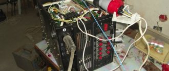
Internal layout
Wire spool
Wire feeder (type 1)
Wire feeder (type 2)
Attaching the welding sleeve to the feed mechanism
Homemade burner design
The most common wire diameters used in semi-automatic welding are 0.8; 1; 1.2 and 1.6 mm. Before welding, the wire is wound onto special reels, which are attachments of semi-automatic devices, fixed to them using simple structural elements. During the welding process, the wire is fed automatically, which significantly reduces the time spent on such a technological operation, simplifies it and makes it more efficient.
The main element of the electronic circuit of the semi-automatic control unit is a microcontroller, which is responsible for regulating and stabilizing the welding current. The parameters of the operating current and the possibility of their regulation depend on this element of the electronic circuit of the semi-automatic welding machine.
Burner
A homemade semi-automatic machine must be equipped with a burner. You can do it yourself, but it’s better to buy a ready-made kit, which includes:
- Burner with a set of tips of different diameters.
- Supply hose.
- Euro connector.
A normal burner can be purchased for 2-3 thousand rubles. Moreover, the device is homemade, so you don’t have to chase expensive brands.
What to look for when choosing a kit:
- what welding current is the torch designed for;
- the length and rigidity of the hose - the main task of the hose is to ensure free flow of wire to the torch. If it is soft, any bend will slow down the movement;
- springs near the connector and burner - they prevent the hose from breaking.
Unit design
Let's look at the most important parts of units made by hand from an inverter in more detail.
Consumable supply unit and burner
When equipping with spare parts, special attention should be paid to a thorough modification of the wire feeder, which will have to move inside the flexible hose.
To obtain a high-quality and neat weld, the wire feed speed must be synchronized with the melting rate of its working part.
Since semi-automatic welding allows the use of several types of wire, made of different materials and having different diameters, its flow rate must necessarily be variable. It is this opportunity that should be provided by the so-called “supply” of consumables, which is organized in accordance with the general requirements for any inverter unit.
Read also: How to properly glue with epoxy resin
When setting up a semi-automatic circuit, consumable wire with sections of 0.8, 1.0, 1.2 and 1.6 mm is most often used. Immediately before starting work, it is wound on pre-prepared reels, which are fixed to the elements of the unit using simple fasteners. Semi-automatic welding involves feeding the wire “self-propelled”, which significantly reduces the time of all operations and increases the efficiency of these procedures.
The torch used in a semi-automatic machine can be taken entirely from a non-working welding unit of the same type or made independently at home. Let’s immediately make a reservation that making a burner with your own hands is a very difficult task, requiring the performer to have certain experience and skills in the manufacture of such devices.
Electronic control module
The electrical circuit of the semi-automatic welding machine is shown in the figure below.
The basic element of the semi-automatic control unit is the microcontroller, which is responsible for selecting the load mode and stabilizing the output current. In addition, the electronic unit includes the following mandatory components and parts:
- Rectifier bridge on high power semiconductor diodes;
- Key transistor circuits;
- Additional winding transformer;
- Correction chokes and inductors.
Particular attention in the composition of the electronic module should be paid to winding inductive products.
A simplified version of the inverter unit is known, which is usually called the “device from Sanych”. Its diagram is shown in the figure below.
Transformer
Another critical component of a semi-automatic machine, made with your own hands from an old welding device, is a transformer, which can be taken from the same inverter (subject to minor modifications).
To ensure the required characteristics of the inverter transformer, which are completely suitable for a semi-automatic device, it is necessary to rewind the old primary coil with a copper strip coated with a layer of heat-resistant paper.
Important! Such transformers cannot be wound with ordinary thick-section copper wire, since they will become very hot under high current loads.
The secondary winding of the old transformer product should also be slightly modified. To do this, you will need to perform the following operations:
- First you need to wind a coil consisting of 3 layers of tin strips, each of which is insulated with fluoroplastic tape;
- Next, the ends of the old and newly wound windings need to be soldered, which will ensure high conductivity of the entire coil;
- It is also necessary to provide a small fan in the set of elements from which the semi-automatic design is assembled (it is intended for additional cooling of the device).
A fan from a failed old PC can be used as such a cooling device installed in welding units.
Preparation
Manufacturing a semi-automatic welding machine at home begins with planning the work. There are two options for making MIG welding from an inverter:
- Completely make a semi-automatic welding machine with your own hands.
- Only remake the inverter - buy a ready-made feeding mechanism.
In the first case, the cost of parts for the feeding device will be about 1000 rubles, excluding labor, of course. If a factory semi-automatic machine includes everything in one case, then a homemade one will consist of two parts:
- Welding inverter.
- Box with feeding mechanism and wire reel.
First, you need to decide on the body for the second part of the semi-automatic device. It is desirable that it be light and roomy. The feeding mechanism must be kept clean, otherwise the wire will feed jerkily; in addition, the reels must be changed periodically and the mechanism adjusted. Therefore, the drawer should be easy to close and open.
The ideal option is to use the old system unit:
- neat appearance - it doesn’t really matter, but it’s much nicer when the insides of the homemade product don’t stick out and the semi-automatic machine made from an MMA inverter looks good;
- light, closes;
- the body is thin - it’s easy to make the necessary cutouts;
- The gas valve and wire feed drive operate on 12 Volts. Therefore, a power supply from a computer will do, and it is already built into the case.
Now you need to estimate the size and location of future parts in the body. You can cut out approximate layouts from cardboard and check their relative position. After this, you can begin work.
The best option for electrode wire is a 5 kg coil. Its outer diameter is 200 mm, inner diameter is 50 mm. For the axis of rotation, you can use a PVC sewer pipe. Its outer diameter is 50 mm.
Pulling device
In a more complex case, the manufacture of a semi-automatic machine involves reworking the arc welding inverter and creating a broaching device from scrap materials. If you had to repair an inverter device, then you can safely implement the second option.
A system unit is ideal as a housing for a drawing device for an inverter-type semi-automatic device. It is quite easy to open, yet spacious and durable.
This will allow you to simply adjust the pressure of the rollers and install the spool of wire. The advantage of the system unit is that it is easy to make holes in the right places, and there is a built-in 12-volt power supply. It is needed to power the additive broach drive and the gas valve.
For the necessary fasteners, it is necessary to make mock-ups of the built-in components from scrap materials and try them on inside the box. After making sure that the selected layouts are correct, you can begin manufacturing the fasteners.
You can buy a reel for a semi-automatic machine ready-made or make it yourself. It is very simple to produce. The diameter of the cheeks should be 200 mm, and the cylinder on which the wire will be wound should have a diameter of 50 mm, so that a plastic pipe with the same rating can be used as an axis.
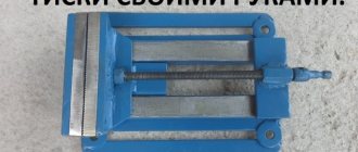
The feed mechanism will require two pressure rollers and one guide roller and a spring. An electric motor from the wipers can be used as a broaching motor. As a base on which the parts will be attached, you need to use a three-millimeter metal sheet.
Holes are drilled in the plate in the right places for attaching the rollers and the electric motor shaft of the future semi-automatic device. Since one roller is a pressure roller, the hole for it is drilled in an oblong shape.
A pressure spring will press on it from above, the force of which is adjusted through a screw. The roller and bearings are mounted on one side of the plate, and the motor on the other. A feed roller is mounted on the motor shaft.
The resulting device is installed inside the system unit so that the alignment of the rollers and the axis of the MIG torch connector are in the same plane. This will prevent the wire from creasing when pulling. To straighten the additive during unwinding, a tube is installed in front of the rollers.
Setting up an inverter used for semi-automatic welding
If you decide to make a semi-automatic welding machine with your own hands using an inverter, you must first turn off the power to this equipment. To prevent such a device from overheating, its rectifiers (input and output) and power switches should be placed on radiators.
Power diodes on additional radiators
In addition, in the part of the inverter housing where the radiator is located, which heats up more, it is best to mount a temperature sensor, which will be responsible for turning off the device if it overheats.
After all of the above procedures have been completed, you can connect the power part of the device to its control unit and connect it to the electrical network. When the network connection indicator lights up, an oscilloscope should be connected to the inverter outputs. Using this device, you need to find electrical pulses with a frequency of 40–50 kHz. The time between the formation of such pulses should be 1.5 μs, which is regulated by changing the voltage value supplied to the device input.
Oscillogram of welding voltage and current: on the left with reverse polarity, on the right with direct polarity
It is also necessary to check that the pulses reflected on the oscilloscope screen are rectangular in shape, and their front is no more than 500 ns. If all the checked parameters correspond to the required values, then you can connect the inverter to the electrical network. The current coming from the output of the semi-automatic device must have a force of at least 120 A. If the current value is less, this may mean that voltage is supplied to the equipment wires, the value of which does not exceed 100 V. If such a situation occurs, you must do the following: test the equipment by changing the current (in this case, it is necessary to constantly monitor the voltage on the capacitor). In addition, the temperature inside the device should be constantly monitored.
After the semi-automatic machine has been tested, it is necessary to test it under load. To make such a check, a rheostat is connected to the welding wires, the resistance of which is at least 0.5 Ohm. Such a rheostat must withstand a current of 60 A. The strength of the current that in such a situation flows to the welding torch is controlled using an ammeter. If the current strength when using a load rheostat does not meet the required parameters, then the resistance value of this device is selected empirically.
Semi-automatic design elements
Photo of a semi-automatic welding machine made by yourself
Mig, Mag, MMA welding requires the use of appropriate devices. Mig Mag is a semi-automatic welding process that is performed in an inert argon gas environment. Sometimes carbon dioxide is used for Mig Mag welding. MMA welding is called manual arc processing with electrodes on which a special coating is applied. If you are working with stainless steel, then MMA welding is carried out only with direct current.
Since we are talking about how you can assemble a full-fledged semi-automatic machine based on an inverter with your own hands, you are not interested in MMA, but in Mig Mag welding.
To assemble a homemade device, a worthy analogue for the Kedr 160, Kaiser Mig 300, with your own hands, you will need a diagram, video instructions and the necessary design elements of the semi-automatic device. These include:
- Inverter. Determine its welding ability by selecting the supplied current. Typically, craftsmen assemble devices capable of delivering 150 Amps, 170 Amps or 190 Amps. The higher the Amps, the higher the ability of your welding device;
- Feeding mechanism. We will tell you about it separately;
- Burner;
- Hose for supplying electrodes;
- A spool of special wire. This attachment is easily attached to the structure in any way convenient for you;
- Control unit for your welding unit.
Now regarding the feed mechanism for a semi-automatic machine and some important points.
- He is responsible for supplying electrodes using a flexible hose to the welding point.
- The optimal feeding speed of the electrode wire corresponds to the speed of its melting during do-it-yourself welding.
- The quality of the seam you make with your own hands depends on the wire feed speed.
- It is recommended to make a semi-automatic machine with the ability to adjust the speed. This will allow you to adapt the semi-automatic device to different types of electrodes used.
- The most popular electrode wires have a diameter from 0.8 to 1.6 mm. It must be wound on a reel and charged the inverter.
- If you provide fully automated feeding, you will not have to do it yourself, and therefore the time spent on welding activities will be significantly reduced.
- The control unit is equipped with a control channel, which is responsible for stabilizing the current.
- The behavior of Amperes, that is, the current of a semi-automatic device, is regulated by a special microcontroller. It performs its work in pulse-width operating mode. The voltage created in the capacitor directly depends on its filling. This affects the welding current parameters.
Preparing a semi-automatic transformer
Scheme of a semi-automatic welding machine made by hand from an inverter
In order for a self-made semi-automatic machine to work no worse than a welding machine like Kedr 160, Kaiser Mig 300, you need to understand the features of transformer preparation.
- Wrap it with a copper strip. Its width should be 4 cm and thickness - 30;
- Before this, the strip is wrapped with thermal paper. The material used in cash registers is suitable. It is not difficult to purchase such paper;
- In this case, the circuit does not allow the use of ordinary thick wiring, otherwise it will begin to overheat;
- The secondary winding must be made by using three layers of tin at once;
- PTFE tape is used to isolate each layer of sheet metal from each other;
- At the output, you will need to solder the contact ends from the secondary winding with your own hands. This is necessary in order to increase current conductivity;
- Be sure to include a fan in the inverter housing. It will serve as a blowing mechanism that reduces equipment overheating.
Inverter setup
There are no problems with the operation of Kedr 160 and Kaiser Mig 300. Cedar 160 and Kaiser Mig 300 are factory equipment that has excellent technical characteristics. These semi-automatic machines function perfectly, allowing you to get the required number of Amperes - 160 Amperes, 170, 190 Amps, etc. It all depends on how you configure the device.
But if you decide to remake the inverter and make it a semi-automatic device, then the idea of buying Kedr 160, Kaiser Mig 300 should be thrown aside.
After completing work with the transformer, you should move on to the inverter. If you make the correct settings for the inverter itself, the modification will bring the desired result. Therefore, a homemade semi-automatic machine will function no worse than a ready-made Kedr 160 or Kaiser Mig 300 device.
- Be sure to provide high-efficiency radiators used for rectifiers (input and output) and power switches. Without them, the device will not be able to work properly.
- A temperature sensor should be installed inside the radiator housing, which heats up the most, to trigger it in case of overheating.
- Connect the power part to the control unit and plug it into the working network.
- When the indicator is activated, you should connect an oscilloscope to the wires.
- Find bipolar impulses. Their frequency ranges from 40 to 50 kHz.
- The time parameters between pulses are adjusted by changing the input voltage. The time indicator must correspond to 1.5 μs.
- Make sure that the inverter produces square wave pulses on the oscilloscope. The edges should not exceed 500 ns.
- When the device has passed the test, connect it to the power supply.
- The indicator built into the semiautomatic device should produce 120 Amperes. Parameters can reach up to 170, 190 Amperes. But if the device does not show this value, you will have to go in search of the reasons for the low voltage in the wires.
- Typically, this situation occurs when the voltage is less than 100 V.
- Now we test the semi-automatic welding machine, starting the device with variable current. At the same time, constantly monitor the voltage on the capacitor.
- We complete the testing by checking the temperature readings.
- Check how the device behaves when loaded. Similar initial tests should be carried out with the Kedr 160 and Kaiser Mig 300. Although the Kedr 160 and Kaiser Mig 300 are factory semi-automatic machines from trusted manufacturers, it will never be superfluous to make sure of their professional suitability.
- To test a homemade inverter or Kedr 160 with a Kaiser Mig 300, you need to connect a 0.5 Ohm load rheostat to the welding wires. Make sure this element can withstand a load greater than 60 Amps. The current parameters are monitored with a voltmeter.
- If checking the semi-automatic device shows that the specified current value and the controlled value are different, the resistance will need to be changed. Do this until you achieve a positive result.
Read also: Share in sales volume
Assembling a device that will act as a full-fledged analogue for the Kedr 160 and Kaiser Mig 300 is not so easy, but it is possible. You yourself determine whether the semi-automatic device will produce 120 or all 190 Amperes. Make choosing a factory model easier. But their price is appropriate. The price of the same semi-automatic Kedr 160 Mig is from 27 thousand rubles. But the decision is yours to make.
Among beginners and professional welders, an inverter-type semi-automatic welding machine is the most popular device. For the former, it provides ease in acquiring welding skills; for the latter, it provides productivity and a large range of additional settings.
Semi-automatic welding equipment can be useful for almost any welder, but has a fairly high cost. If you have manual arc welding, you can convert it into a semi-automatic inverter type.
Remodeling methods
To begin with, let's consider possible options for converting an inverter into a semi-automatic welding machine.
To create a semi-automatic device, you will definitely need a so-called head unit. This is, in fact, a welding machine, which will form the operating parameters for the occurrence of an arc discharge. Not every inverter model is suitable as such a head unit.
It is necessary to choose a sufficiently powerful welding machine. Its current-voltage characteristics can be changed using a pulse-width modulation controller. However, firstly, not every home craftsman has such a device. Secondly, the measurement process is very long and labor-intensive. Finally, only a person with a sufficiently high level of knowledge in electrical engineering can carry out all the research.
Since the option with a PWM controller will not be available to the average welder, it is recommended to take a simpler route. Firstly, the selected donor device must normally perform all necessary operations. Secondly, to create a homemade semi-automatic you will need a choke. This part, intended for fluorescent lamps, can be purchased at any spare parts store. The inductor output voltage is used as a feedback input. How exactly to make a connection diagram and carry out the necessary installation operations is shown in the video below.
This option for creating a homemade semi-automatic machine is suitable only for happy owners of high-quality equipment. Namely, inverters capable of operating in a strictly specified current-voltage characteristic mode. Welders of this class are expensive, but they are most suitable for solving the task.
To make your own semi-automatic device, you will need:
- buy a wire feeder, complete with all the necessary wires and switching connectors;
- connect the feed mechanics to the inverter welding machine;
- select the current-voltage characteristic to work with a specific type of wire.
Wire feeder from Aliexpress
In essence, the feed mechanism acts as an attachment that expands the capabilities of the welding inverter. However, such a scheme has increased reliability and does not require special knowledge from the user. In addition, the resulting semi-automatic machine shows the maximum level of flexibility and unpretentiousness: it can be quickly configured to work with a specific material and wire.
This method will require considerable preparation from the user. Firstly, he will need to find a non-average inverter welding machine of suitable power. It is necessary to select the simplest possible donor of a certain class. The ideal device would be one that:
- there is a shunt at the output;
- a current transformer is used in the primary conversion block;
- ZX-7 layout.
It is recommended to choose devices without additional control options and functionality to make the life of the welder easier. The inverter should not have any hot starts, simple ignition, or arc forced.
To create your own homemade semiautomatic device, you will need to accurately set the current-voltage parameters of the selected inverter. You will also need to adjust the current increase. The order and list of required work is not universal. It differs for different inverter models.
Volt-ampere characteristics of the welding inverter
Semiautomatic from inverter
There are several ways to make a working semi-automatic device from an inverter. We will list the most interesting, in our opinion. You can implement them at home with basic knowledge of electrical engineering.
Method No. 1
To make an inverter semi-automatic welding machine with your own hands, you will need a “donor”. Without it, it’s simply not possible to make a semi-automatic machine. As a “donor”, take not the weakest inverter for MMA welding. It must be operational and perform normal welding operations without any problems.
You need to change the current-voltage characteristics of the inverter you have chosen so that it can operate in semi-automatic welding mode. You can use a PWM controller for this. However, this option is very labor-intensive and is not suitable for those who are not strong in electrical engineering.
Therefore, in order to assemble a semi-automatic welding machine from an inverter with your own hands, we recommend making a choke. A choke from a fluorescent lamp is suitable for this. And after the throttle you need to take the feedback voltage. Watch the video below, which explains the essence of this method in detail. There is also a clear diagram in the video.
Method No. 2
The second method is extremely simple and is suitable for those who have a certain inverter welding. The fact is that there are inverters on sale that can switch to a mode with a rigid change in the current-voltage characteristic. If you are the owner of just such an inverter, then you can only be happy for yourself. To turn such a device into a semi-automatic machine, you just need to purchase an external feed mechanism.
The mechanism must include all the necessary cables and connectors. You just need to easily connect the welding wire feeder to the welding inverter and you can start welding. We can assume that in this case the feed mechanism works as an attachment to the inverter for semi-automatic welding. Watch the video below, where the author talks about his inverter, to which he connected the feeder.
Method No. 3
The last method of converting from a welding inverter into a semi-automatic machine with your own hands will require some knowledge and skills. In this case, you will also need a donor inverter. Please note that not every device will work. You need an inverter with ZX-7 layout. It must have a shunt at the output, and there must be a current transformer at the “primary”. It’s even better if the device doesn’t have any additional functions like hot start or arc force.
You also need to change the current-voltage characteristics, and also set the current rise setting. Further actions directly depend on the circuit of your inverter. So don’t be lazy to find topics on various forums dedicated to converting an inverter into a semi-automatic machine. Watch the video below with a test of such a homemade device.
Inverter conversion process
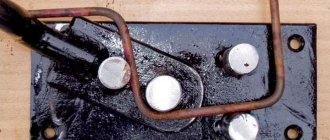
In a finished inverter, you first need to remake the transformer included in it. It is covered with an additional layer consisting of copper strip and thermal paper.
Ordinary copper wire cannot be used for a welding transformer. When welding, it overheats greatly and can stop the operation of the entire semi-automatic welding machine.
The secondary winding of the transformer will also require intervention. It is covered in three layers of tin, insulated with fluoroplastic tape. The ends of the applied winding are soldered. As a result of manipulation, the conductivity increases significantly.
An important element is a fan that will cool the device, protecting it from overheating.
An inverter for manual welding can easily be converted into a power source for a semi-automatic machine. A functioning device does not need to be disassembled, but all additional equipment is placed in a separate housing. It houses a freely rotating spool of welding wire and a pulling mechanism. The side panel displays a wire speed regulator and a socket for connecting a hose.
An old computer system case will do just fine. It turns out compact and neat.
The current parameters can be adjusted on the inverter, then the “positive” terminal is connected to the workpiece from it.
The “negative” contact is removed from the inverter and goes into the new housing. Here it is connected to the sleeve terminal. It is important that the welding wire is connected to this potential.
The gas hose running from the cylinder to the burner is also attached to the housing. If you use the valve from a car windshield wiper, the gas supply will be adjusted.
The above arrangement is simple to implement, and the inverter can be simultaneously used for manual arc welding and as a power source for a home-made semi-automatic machine.
Creating a wire feeder
This block is needed to uniformly introduce consumables into the weld pool. The wire is selected taking into account the type of metals being connected and the result of the work. The feed mechanism must adapt to any type and size of consumables. The finished device is purchased at an electrical goods store.
It is allowed to make a unit with your own hands from the following improvised means:
- motor from car wipers;
- pressure shaft with spring;
- 3 bearings;
- metal plates 1 cm wide.
All parts are installed on a 5 mm thick textolite stand. The wire is inserted between the shaft and the bearing. The point where the filler material is discharged is compared with the fastening of the end of the hose used for gas inlet.
The wire is wound onto the reel evenly, the strength of the welded joints depends on this. The coil is placed on a support and secured. During operation, the wire unwinds and enters the seam. This mechanism facilitates and speeds up the welding process.
Assembly of the unit
The assembly instructions will help you make a quality semi-automatic welding machine. The work is carried out in the following sequence:
- Connect the inverter to power and control devices.
- Thread the wire into the feed mechanism and check for smooth movement.
- Set the required wire feed speed.
- Connect the burner to a hose, which is connected to the feeder.
- Connect a gas cylinder with a reducer and a pressure gauge to the burner.
- Turn on the inverter and feeder.
- Check the flow of gas and wire. After gas supply, the delay in wire movement should be 1–2 s. It enters a ready-made protective environment, otherwise it will stick.
When preparing a home-made semi-automatic machine for the first start-up, you need to take care of cooling the assembled semi-automatic welding machine so that it does not overheat. For this purpose, input and output rectifiers and power switches are mounted on radiators. On the inverter body where the radiator is located, that is, in the most heated zone, it is recommended to install a temperature sensor that will de-energize the device if it overheats.
After this, connect the power part to the control unit, and then turn on the semi-automatic device to the power supply. When the mains lights come on, the inverter needs to be tested. At the output of the device, a current is measured, which should not exceed 120 A. If its value is less, this means that a voltage below 100 V is supplied to the equipment through the wires. In this case, the current is changed and the voltage is controlled, achieving the desired parameters. In this case, the inverter should not overheat.
Under load, the semi-automatic device is checked as follows. The welding wires are connected to a rheostat designed for a current of 60 A and a resistance of at least 0.5 Ohm. The current supplied to the burner is controlled with an ammeter. If the current strength differs from the norm, change the resistance value.
After turning on the assembled semi-automatic device, the indicator should show a current strength of 120 A. This figure confirms the correctness of the work. If eights are displayed, then the reason is insufficient voltage in the supply wires. Welding inverters operate in the operating current adjustment range of 20–160 A.
DIY making
The easiest way is to make a homemade semi-automatic machine from an inverter based on a powerful power unit.
You can make an inverter yourself or use it from existing equipment. For semi-automatic devices, inverters with a capacity of at least 150 amperes should be used. There are schemes for modifying equipment that allow you to set the power that will be enough to carry out semi-automatic welding. A device of this type will be difficult to implement, so the use of low-power power units can only be recommended to experienced radio amateurs who can produce truly complex equipment.
You can produce high-quality equipment if you have on hand the starting circuit for a semi-automatic welding inverter. The characteristics of such a unit include the following:
- Primary current - 8-12 A.
- Supply voltage - 220 or 380 volts.
- Open circuit voltage is 36-42 Volts.
- Welding current - 40-120 amperes.
- Voltage adjustment in increments of plus or minus 20%.
These are the optimal parameters for a household semi-automatic welding machine that can cope with metals of different refractoriness indices. Subsequently, using additional drawings for increasing the power of the inverter, you can change the basic characteristics, which allows you to use such equipment for domestic and industrial purposes .
Rework algorithm
The vast majority of components are used without significant modifications. Re-equipment will be required for the filler material feeder, since the feed rate of the filler through the flexible hose must match the melting rate of the filler metal. It is necessary to take into account the adjustment option in the mechanism, because the speed varies based on the type of metal being welded, the type and cross-section of the filler material.
In a working inverter, first of all, the transformer device included in its structure should be rearranged. It is covered with an additional layer consisting of a copper strip and paper with a heat-sensitive coating.
Do not use ordinary copper wire for the transformer device. During the welding cycle, it heats up too much and can stall the operation of the entire semi-automatic welding unit.
The secondary winding of the transformer device also requires improvement. It is covered in 3 layers of thin sheet steel, insulated with fluoroplastic tape. The ends of the wound winding are connected by soldering. After performing these steps, electrical conductivity increases significantly.
An important component is the fan, which will cool the unit, protecting it from excessive heating.
A current converter for manual electric welding very easily becomes a power source for a semi-automatic unit. The working device can not be disassembled, and all auxiliary equipment can be located in another building. It contains a reel with filler material, which rotates freely on the drum, and a feeding device. On the side of the casing there is a speed converter for the filler material and a connector for connecting the guide hose.
A used PC system case will easily do. It will turn out neat and concise.
The parameters of the electric current can be adjusted on the inverter, therefore, the “positive” terminal is connected to the part from it.
“Minus” is removed from the inverter and inserted into a new supporting shell. Here it is connected to the terminal of the supply hose. The main thing is that the filler material is connected to this potential.
The hose for supplying the protective gas mixture, which runs from the cylinder to the burner gun, is also fixed in the housing. If you use the valve from the car's windshield wipers, the gas mixture supply setting will appear.
The presented assembly is simple to implement, and the inverter can be used in parallel for manual electric arc welding and as a power source for a welding unit made at home, operating in a semi-automatic mode.
How to monitor the correct operation of equipment
In order for the semi-automatic welding machine that you assembled with your own hands to serve you for a long time, it is better to constantly monitor the temperature conditions of the inverter. To carry out such control, you need to press two buttons simultaneously, after which the temperature of the hottest inverter radiator will be displayed on the indicator. The normal operating temperature is considered to be one whose value does not exceed 75 degrees Celsius.
If this value is exceeded, then, in addition to the information displayed on the indicator, the inverter will begin to emit an intermittent sound signal, which should be noted immediately. In this case (as well as if the temperature sensor breaks or shorts), the electronic circuit of the device will automatically reduce the operating current to 20A, and a sound signal will be emitted until the equipment returns to normal. In addition, a malfunction of self-made equipment may be indicated by an error code (Err) displayed on the inverter indicator.
Setting the welding mode on the Resanta inverter
How to use a welding inverter
After starting the semi-automatic device that you assembled with your own hands, the inverter indicator should display a current value of 120 A. If everything is done correctly, then this will happen. However, the inverter indicator may display a figure of eight. The reason for this is most often insufficient voltage in the welding wires. It is better to immediately find the cause of such a malfunction and promptly eliminate it.
If everything is done correctly, the indicator will correctly show the strength of the welding current, which is adjusted using special buttons. The operating current adjustment interval provided by welding inverters is in the range of 20–160 A.
Approximate modes of semi-automatic welding of butt seams
Testing a semi-automatic device in operation
After starting the self-assembled semi-automatic device, its indicator panel should display a current value corresponding to the operating value of 120 Amperes. At the same time, you should check the readings of the sensors installed on the cooling radiators of the homemade product (the temperature in their area of action should not exceed 100 degrees).
You will also need to check the adjustment range of the output (load) current, which cannot be less than 20-160 Amperes.
In conclusion, we note that a semi-automatic machine, made by hand in compliance with all the rules discussed in this review, will be able to serve its owner for quite a long time. Its performance and reliability will largely depend on the quality of the components used and the reliability of their assembly.
Semi-automatic Sanych
Craftsman Sanych offers a semi-automatic welding circuit that is simple and accessible even for beginners.
The proposed design is characterized by a soft hiss of the arc, while crackling and clicking noises are observed in magazine devices. The hard mode is obtained there due to the output characteristics of the transformer 18–25 V.
The transformer consists of four cores from the TS-270 connected together. The result is almost 2 thousand watts. This power is sufficient with reserve. The primary winding (180+25+25+25+25) is made of wire with a cross-section of 1.2 mm. For the secondary (35+35 turns) an 8 mm² bus is used. The number of turns of the secondary winding is determined last, so it is better to make a couple of turns in each arm with a reserve. The excess can be rewinded.
Welding device diagram:
The rectifier circuit is full-wave. To switch the current there is a paired bib. Two diodes in a small radiator. It is recommended to take capacitors of at least 30 thousand microfarads.
The power part is switched on by any of the powerful contactors, for example models KM-50D-V or KP-50D-V. With the passport data 27 V and at 15 V they work stably. The contactor allows you to obtain high switching power at the lowest current of 300–400 mA.
The TS-40 supply transformer is rewound to give an output voltage of 15 V.
For the broaching mechanism, a roller with a diameter of 25–28 mm is used. On the guide you need to make a groove 0.5 mm wide by 1 mm deep. It is secured to the motor shaft with a nut. The output of the regulator is 6 V, and this is enough for optimal supply. If the lower limit is exceeded, a stabilizer with a lower operating voltage is selected.
The handle holder is machined from textolite sheets 10 mm thick. The seats are made with a drill using drills and an end mill.
The protection hose is held in place on both sides by spacer sleeves. For reliability, there are grooves on the mating parts.
The body will require a 1 m thick sheet of iron with a double flange along the edge. The cooling fan is installed on the rear wall, just opposite the power transformer. The semi-automatic welding machine moves on wheels.
The assembled semiautomatic device is connected to the network for testing. It should not overheat and clearly respond to current adjustment. The transformer insulation is also checked. In case of problems, additional coating is applied. You also need to check the feeding mechanism: how evenly and quickly it feeds the wire. The device has worked faithfully for more than 10 years.
A well-made semi-automatic machine will serve its owner for a long time and reliably, and if you have experience in making a semi-automatic welding machine with your own hands, be sure to share it in the comments to this article.
A semi-automatic welding device for household needs can be purchased ready-to-use or completely assembled with your own hands. A homemade semi-automatic machine will cost the performer much less, but its assembly will require certain skills in working with electrical equipment. The appearance of such a welded device is shown in the figure below.
We recommend that everyone who wants to make a semi-automatic machine from an inverter with their own hands first familiarize themselves with the structure of this unit and the operating features of the modules included in it.