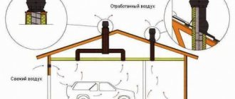
An electric current of high strength (hundreds of amperes) and high frequency (tens - hundreds of kHz) is passed through a copper loop - an inductor. As a result, Foucault currents, also of high strength and frequency, are induced in the metal workpiece standing inside or next to the inductor. The high-frequency current in the workpiece under the influence of the skin effect is forced into thin surface layers, as a result of which its density increases sharply. The workpiece layer, through which large currents flow, begins to quickly heat up. The temperature can reach several thousand degrees, which allows you to melt metal at home, invent and create your own unusual alloys; weld and solder metal parts; harden screwdrivers, drills, knives, etc., use the installation in forges and repair shops.
Induction heating allows you to heat electrically conductive materials (any metal, graphite, electrically conductive ceramics) without contact. Directly through air, through a layer of water, through a glass, wood or plastic wall, in a vacuum chamber or in a chamber with protective gas. At the same time, the workpiece remains perfectly clean, since it does not oxidize in the gas stream, does not touch the dirty surface of the stove, etc.
The inverter of Sergei Vladimirovich Kukhtetsky, developed at the Institute of Chemistry, was taken as the basis. The inverter circuit, its detailed description and assembly recommendations are published at: www.icct.ru The circuit uses modern electronic components, which allows you to assemble a powerful and reliable inverter at home for a low price of about a few thousand rubles (prices for industrial analogues reach tens and hundreds of thousands of rubles).
On the induction.listbb.ru forum, in joint efforts with forum members Derba, Phoenix, Jab, Fulyugan, Ostap, -CE-, the circuit was finalized, an additional PLL phase-locked loop board was installed to automatically maintain resonance, high-speed protection against overcurrent was installed (as with excess power supply, or as a result of breakdown of power mosfets due to their overheating or failure of the control module). Some details have been added to reduce the likelihood of mosfets overheating and control module failure (leading to the appearance of through currents in the power bridge).
• Inverter power consumption depending on the inductors used: 1. 4 kW. • Current frequency in the inductor: 300 kHz. • Current strength in the inductor:
400A. • The maximum current consumed from the network with a two-turn inductor is 20A, the voltage consumed is 220V.
The induction heater is equipped with protection that turns off the circuit when the supply voltage is exceeded, when the inductor is short-circuited, or when the inductor is flooded with water.
See diagrams and discussion of improvements on the forum: induction.listbb.ru here and here
Video - melting low-carbon steel (nuts) in air:
Video - melting high-carbon steel (a ball from a bearing made of ShKh-15 steel):
Video - melting low-carbon steel in protective gas (argon):
Video - heating a steel ball through a layer of water. The possibility of heating a piece of iron through a layer of water is interesting; water is not an obstacle to the electromagnetic field
A powerful high-frequency electromagnetic field pushes iron blanks out of the inductor. On the one hand, this creates problems - it is difficult to heat small workpieces, they are carried away from the inductor and you have to somehow secure them (the so-called electromagnetic blast effect). On the other hand, you can melt metal in a suspended state - (levitation melting, melting in an electromagnetic crucible):
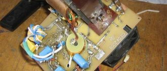
Modification of the inverter for induction heating.
The method of non-contact heating of liquid metal samples with high frequency currents in a vacuum or protective gas is optimal for experiments with small samples of electrically conductive materials.
Industrial high-frequency inverters do not have the characteristics necessary for the experiment (high power at high frequency required for heating small samples), and therefore a homemade inverter was made. The inverter developed by Sergei Kukhtetsky at the Institute of Chemistry and Chemical Technology of the Russian Academy of Sciences was taken as the basis, working as follows. The inductor for heating the samples, which is an oscillating circuit coil together with a compensating bank of capacitors, is pumped from an independently operating high-frequency generator.
The generator is made according to a full bridge circuit; its frequency is automatically adjusted to the natural frequency of the oscillatory circuit manually and cannot be changed during operation. The proposed inverter does not have a circuit for protecting power transistors from through currents and a heating power control circuit (Fig. 1).
Fig.1. Block diagram of a simple inverter for induction heating.
Operation of this simple inverter revealed the following problems. As a result of heating the sample, as well as as a result of the movement of the sample in the inductor, a change occurs in the inductance that is part of the oscillatory circuit and a change in its natural frequency. Since the operating frequency of the inverter is set by the generator with a frequency that does not change during operation, a mismatch between the frequencies of the oscillatory circuit and the generator leads to a sharp drop in heating power, vibrations of the workpiece in the inductor, as well as power transistors entering a non-optimal operating mode in capacitive mode, which leads to their failure building.
To solve these problems, the inverter was retrofitted with a PLL phase-locked loop circuit, a high-speed protection circuit for power transistors from overcurrent, and a switching power regulator controlled from a PC. Protection and power control circuits are designed as separate modules and can be used for other tasks.
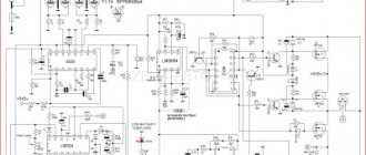
The PLL circuit consists of a variable frequency oscillator, a current sensor, a voltage sensor, an adjustable delay line, and a control pulse shaper for the power bridge. Current and voltage sensors measure the corresponding values on the oscillating circuit, after which their phases are compared. Zero phase shift means synchronous operation of the oscillatory circuit at its own frequency and the master oscillator. In the event of a phase shift, the master oscillator automatically adjusts the frequency, adjusting it to the natural frequency of the oscillatory circuit (Fig. 2). The electrical circuit of the modified inverter is shown in Fig. 5.
Setting the PLL tracking range, procedure:
It is necessary to determine the natural frequency of the oscillatory circuit, for example, as follows.
1) Remove the matching transformer from the busbars of the oscillatory circuit.
2) Connect an oscilloscope to the buses connecting the inductor to the capacitor bank.
3) Set the oscilloscope to standby mode (single measurement Trigger mode).
4) Briefly touch the busbars of the oscillating circuit with a crown battery. “Bounce” will appear on the screen - the circuit’s own vibrations. If necessary, carry out this procedure several times to obtain a stable picture on the oscilloscope screen.
The period of natural oscillations is measured using the oscilloscope grid, then using the formula f = 1 / period , the natural frequency of the oscillating circuit is calculated.
The PLL operating range is configured as follows.
1) An oscilloscope is connected to the output of the CD4046 PLL oscillator chip.
2) Set the minimum operating frequency of the CD4046 generator. To do this, connect the plus of the 1-volt power supply to pin 9 of the CD4046 microcircuit, and connect the minus of the power supply to the common bus.
3) Set the minimum frequency by rotating the potentiometer on pin 12 of the cd4046 microcircuit to 30 kHz below the natural frequency of the oscillatory circuit (selected experimentally for reliable PLL pickup).
4) Set the maximum operating frequency of the CD4046 generator. To do this, connect the plus of the 4.5 volt power supply to pin 9 of the CD4046 microcircuit, and connect the minus of the power supply to the common bus.
5) By rotating the potentiometer on leg 11 of the CD4046 microcircuit, set the frequency 30 kHz higher than its own.
As a result of the operations performed, the inverter automatically starts picking up the resonance and maintains it during operation.
Fig.2. Block diagram of an induction heating inverter with PLL.
The protection module consists of a current sensor mounted on a shunt, an overcurrent detection circuit with an adjustable response threshold, and a power shutdown circuit. Power is supplied to the inverter through a shunt. At the moment the current exceeds the shunt, an excess voltage drop is detected, which leads to the flip-flopping of the trigger and the supply of a turn-off signal to the power transistor (Fig. 3). The electrical diagram of the protection module is shown in Fig. 6.
Fig.3. Block diagram of the high-speed protection module.
Video - activation of the high-speed protection module:
The switching power regulator is made according to the circuit of a step-down PWM converter. Power regulation is carried out by changing the duty cycle of the control PWM signal. The control signal is generated by the STM32F767 microcontroller (a ready-made debug board with a built-in USB programmer). Power control parameters are set from a computer via the USB interface included in any PC; this solution allows you to synchronize data collection and control of the experimental setup (the block diagram is shown in Fig. 4).
Operating principle of the HDTV installation
The coil creates a high-frequency magnetic field, and eddy currents appear in the metal object in the middle of the coil, which will heat it up. Even small coils pump a current of about 100 A, so a resonant capacitance is connected in parallel with the coil, which compensates for its inductive nature. The coil-capacitor circuit must operate at their resonant frequency.
Homemade HDTV coil
The principle of induction heating technology
The principle of induction heating technology is quite simple from a physical point of view. A coil formed from a current conductor generates a high-frequency magnetic field. In turn, a metal object placed in the inner region of the coil induces eddy currents. As a result, the object becomes very hot.
In parallel with the inductor, a resonant capacitance is usually switched on. This step is taken to compensate for the inductive nature of the coil. The resonant circuit created by the coil-capacitor elements is excited at its own resonant frequency. The value of the excitation current is significantly less than the value of the current flowing through the inductor.
Electrical circuit diagram
Here is the original circuit of the induction heater generator, and below it is a slightly modified version, according to which the design of the mini HDTV installation was assembled. There is nothing in short supply here - you only have to buy field-effect transistors; you can use BUZ11, IRFP240, IRFP250 or IRFP460. The capacitors are special high-voltage, and the power will be from a 70 A/h car battery - it will hold current very well.
The project turned out to be surprisingly successful - everything worked, although it was assembled “on the knee” in an hour. I was especially pleased that it does not require a 220 V network - car batteries allow you to power it even in the field (by the way, can you make a camp microwave out of it?). You can experiment in the direction of reducing the supply voltage to 4-8 V as from lithium batteries (for miniaturization) while maintaining good heating efficiency. Of course, it won’t be possible to melt massive metal objects, but it will work for small jobs.
The current consumption from the power supply is 11 A, but after warming up it drops to about 7 A, because the metal resistance increases noticeably when heated. And do not forget to use thick wires here that can withstand more than 10 A of current, otherwise the wires will become hot during operation.
Heating a screwdriver to blue HDTV
Heating the knife HDTV
ZVC driver circuit
Standard generator option
Strengthened version of the circuit
But apparently it is not my destiny to become one of them.
All the necessary parts were purchased - new field-effect transistors, new fast diodes and zener diodes. Before soldering, everything was tested on a transistor tester, including to determine the correct pinout.
A gorgeous coil of pure copper with a diameter of 5 mm was assembled. But this device stubbornly refused to work.
Suspicion fell on the chokes, which most radio amateurs recommend winding on yellow powder rings from the ATX power supply.
Extraction of the required items and installation also turned out to be ineffective - the induction metal heater had not worked before and was not going to work anymore. Connecting different types of coils together with capacitors of different capacities did not change the picture - “the fish opens its mouth, but you can’t hear what it’s singing,” that is, the transistors open, the current is drawn, but generation does not occur.
In the end, I got pretty tired of all this, the multi-day dance with the tambourine ended, and I had to bow to the Chinese on their Aliexpress and order a ready-made generator module for $7.
After 2 weeks, this thing was delivered by courier directly to your home and, after connecting to a 12 V computer power supply, it started working successfully.
Moreover, it worked from 5 volts, and with a small standard coil, and with a large homemade one, in general, it generated a powerful electromagnetic field in all positions (with the same parts and circuit). Heats a 3 mm pin to red hot in 20 seconds. I fiddle with the 6 mm piece of iron for several minutes, while it itself gets terribly hot (mainly the transistors and the coil).
I don’t even know what to blame here. Maybe the capacitors are wrong, maybe the transistors. In any case, the fact remains: the industrial board worked, but the homemade one did not. So whoever wants can safely throw a piece of rosin at me, others can sympathize, and still others can try to assemble this induction unit themselves and write in the comments about the results.
The second version of the circuit is powered from the network
To make it more convenient to adjust the resonance, you can assemble a more advanced circuit with the IR2153 driver. The operating frequency is adjusted by a 100k regulator at resonance. Frequencies can be controlled in the range of approximately 20 - 200 kHz. The control circuit needs an auxiliary voltage of 12-15 V from the mains adapter, and the power part through a diode bridge can be connected directly to a 220 V network. The inductor has about 20 turns of 1.5 mm on an 8x10 mm ferrite core.
Diagram of an induction heater from a 220V network
The working HDTV coil should be made of thick wire or better copper tube, and has about 10-30 turns on a 3-10 cm mandrel. Capacitors 6 x 330n 250V. Both get very hot after a while. Resonant frequency is about 30 kHz. This homemade induction heating installation is assembled in a plastic case and has been working for more than a year.
Source: 2shemi.ru
Homemade induction heater according to working diagram
Electromagnetic induction is the appearance of electric current when interfering with a magnetic field. Engineers have been able to develop heaters that work on this principle. The Plumber Portal website presents diagrams on how to make an induction heater with your own hands for domestic use. But first you need to understand on what principle this equipment works.
Operating principle of an induction heater
After Faraday's discovery of electromagnetic induction in 1831, the force of induction began to be used in industry, various motors and generators, and in transformer devices. Heaters were created that operated on the same induction principle as a furnace for melting metal. A little later they began to manufacture household appliances.
So, electromagnetic induction occurs in a winding of wire wound around an iron core.
When disassembling an induction boiler, you can see that its design includes: a core, electrical and thermal insulation, and in addition the body itself. This heater differs from industrial heaters mainly in the presence of a toroidal winding with copper conductors. Its location is between two pipes welded together.
The material for the manufacture of these pipes is ferrimagnetic steel. The walls of such pipes have a thickness of more than 10 mm. Thanks to this type of design, the heater weighs much less, its dimensions are more compact, and the efficiency is much higher.
The core here is a pipe with a winding. The other is necessary for direct heating of the coolant. The induction current generated by the high-frequency magnetic field from the external winding to the pipe serves to heat the coolant. This process causes vibration of the walls, which prevents scale from depositing on them.
Due to the heating of the core during operation, the coolant also heats up. The core temperature increases due to eddy currents. They are formed due to the magnetic field generated by high voltage currents. This is the basic principle of induction water heaters, as well as most modern boilers.
Application of induction force for heating
Heating devices that use electricity as the basis for their operation are definitely the most convenient and most comfortable to use. Their safety is much higher than that of equipment that runs on gas. In addition, these devices do not leave soot and soot as residual products of their operation.
The main disadvantage of such devices, perhaps, can be called high energy consumption. For greater savings, craftsmen have figured out how to make induction heaters themselves. As a result, you get a unit that requires significantly less electricity to operate.
Simple 12V Induction Heater
A simple induction heater consists of a powerful high-frequency generator and a low-resistance coil-circuit, which is the load of the generator.
A self-excited generator generates pulses based on the resonant frequency of the circuit. As a result, a powerful alternating electromagnetic field with a frequency of about 35 kHz appears in the coil.
If a core of conductive material is placed in the center of this coil, electromagnetic induction will occur inside it. As a result of frequent changes, this induction will cause eddy currents in the core, which in turn will lead to the release of heat. This is the classic principle of converting electromagnetic energy into thermal energy.
Induction heaters have been used for a very long time in many areas of production. With their help, you can do hardening, non-contact welding, and most importantly, spot heating, as well as melting of materials.
The Plumber Portal resource will show you the circuit of a simple low-voltage induction heater, which has already become a classic.
Let’s simplify this circuit even further and won’t install zener diodes “D1, D2”.
Items you will need:
- 10 kOhm resistors – 2 pcs.
- 470 Ohm resistors – 2 pcs.
- Schottky diodes 1 A – 2 pcs.
- Field effect transistors IRF3205 – 2 pcs.
- Inductor “5+5” - 10 turns with a tap from the middle. The thicker the wire, the better.
- Throttle - 25 turns on a ring from an old computer block.
- Capacitor 0.47 µF. It is better to collect the capacitance with several capacitors and for a voltage of at least 600 Volts.
Making a simple 12V induction heater:
- Wind the inductor.
- Assemble the circuit using a hinged mounting, separating the inductor from the entire circuit with a block.
- It is advisable to place the capacitor in close proximity to the coil terminals.
- Install transistors on radiators.
- Power the entire installation from a 12 Volt battery.
Works great. The blade of a stationery knife heats up to red very quickly.
Transistors and the inductor itself heat up if they work constantly. For a short time - almost not critical.
Diagram and description of a 500 Watt induction heater
Diagram of a 500 Watt induction heater that you can assemble yourself! You can find a huge variety of these schemes on the Internet, but they immediately become uninteresting, since for the most part they are either completely non-working or do not function as expected. But the above induction heater circuit has been tested and is absolutely working, but its main advantage is its simplicity, which everyone will appreciate.
Manufacturing instructions
To produce a furnace, you will need the following tools and materials:
- soldering machine;
- solder;
- textolite board.
- mini drill.
- radioelements.
- thermal paste.
- chemical reagents for etching the board.
Additional materials and their specifics:
- To produce a coil that will emit the alternating magnetic field necessary for heating, you need to prepare a piece of copper tube with a diameter of 8 mm and a length of 800 mm.
- Powerful power transistors are a very expensive part of a homemade induction installation. To install the frequency generator circuit, you need to prepare 2 similar elements. Transistors of the following brands are suitable for these purposes: IRFP-150; IRFP-260; IRFP-460. During the manufacture of the circuit, 2 similar of the indicated field-effect transistors are used.
- To produce an oscillating circuit, you will need ceramic capacitors with a capacity of 0.1 mF and an operating voltage of 1600 V. In order for a high-power electric current to appear in the coil, 7 such capacitors will be needed.
- During operation of such an induction device , the field-effect transistors will become very hot and if heating devices made of aluminum alloy are not connected to them, then after a couple of seconds of operation at the highest power, these parts will break. Transistors should be installed on heat sinks through a thin layer of thermal paste, otherwise the effectiveness of such cooling will be minimal.
- Diodes that are used in an induction heater must certainly be ultra-fast. The most suitable diodes for this circuit are: MUR-460; UF-4007; HER – 307.
- Resistors used in circuit 3: 10 kOhm with a power of 0.25 W - 2 pcs. and 440 Ohm power - 2 W. Zener diodes: 2 pcs. with an operating voltage of 15 V. The power of the zener diodes must be at least 2 W. A choke for connecting to the power terminals of the coil is used with induction.
- To power the entire device, you will need a power supply with a power of up to 500 watts. and a voltage of 12 - 40 V. This device can be powered from a car battery, but it will not be possible to obtain the highest power readings at such a voltage.
Basic rules and recommendations
It is recommended to use these systems in closed heating circuits with forced circulation of coolant. These devices can be used with plastic pipelines.
The boiler must be installed so that there is at least 30 cm between it, walls and other devices powered by electricity. A distance of 80 cm must also be maintained from the floor and ceiling.
In addition, experts strongly recommend installing a security system on an inductive device behind the outlet pipe. To do this, you will need a pressure gauge, an air release device and a blast valve.
Thus, now you know how to make an induction heater with your own hands without extra investment and hassle. This unit will serve faithfully for a single year, heating your home. The assembly diagram is quite simple and its installation will only take a couple of hours.
Source: santehnikportal.ru
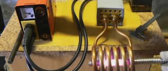
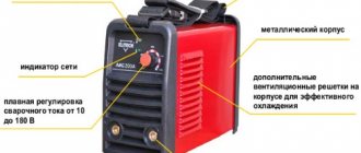
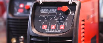
Do-it-yourself HDTV from a welding inverter - Metalworker's Guide
Electric heating devices are extremely convenient to use.
They are much safer than any gas equipment, they do not produce soot and soot, unlike units running on liquid or solid fuel, and finally, they do not need to prepare firewood, etc.
The main disadvantage of electric heaters is the high cost of electricity. In search of savings, some craftsmen decided to make an induction heater with their own hands. They received excellent equipment that requires much less expense to operate.
Working principle of induction heating
An induction heater uses the energy of an electromagnetic field, which the heated object absorbs and converts into heat. To generate a magnetic field, an inductor is used, i.e. a multi-turn cylindrical coil. Passing through this inductor, an alternating electric current creates an alternating magnetic field around the coil.
A homemade inverter heater allows you to heat quickly and to very high temperatures. With the help of such devices you can not only heat water, but even melt various metals
If a heated object is placed inside or near the inductor, it will be penetrated by the flux of the magnetic induction vector, which constantly changes over time.
In this case, an electric field arises, the lines of which are perpendicular to the direction of the magnetic flux and move in a closed circle.
Thanks to these vortex flows, electrical energy is transformed into thermal energy and the object heats up.
Thus, the electrical energy of the inductor is transferred to the object without the use of contacts, as happens in resistance furnaces.
As a result, thermal energy is spent more efficiently, and the heating rate increases noticeably. This principle is widely used in the field of metal processing: melting, forging, soldering, surfacing, etc.
With no less success, a vortex induction heater can be used to heat water.
Induction heat generator in a heating system
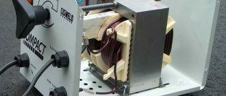
To organize heating of a private house using an induction heater, the easiest way is to use a transformer, which consists of a primary and secondary short-circuited winding.
Eddy currents in such a device arise in the internal component and direct the resulting electromagnetic field to the secondary circuit, which simultaneously serves as a housing and a heating element for the coolant.
Please note that not only water, but also antifreeze, oil and any other conductive media can act as a coolant during induction heating. In this case, the degree of purification of the coolant does not matter much.
The inverter heater is compact in size, operates silently and can be installed in almost any suitable location that meets safety requirements
An induction heating boiler is equipped with two pipes.
The lower pipe, through which the cold coolant will flow, must be installed at the inlet section of the pipeline, and at the top, a pipe is installed that transfers the hot coolant to the supply section of the pipeline. When the coolant in the boiler heats up, hydrostatic pressure arises and the coolant enters the heating network.
There are a number of advantages to using an induction heater that should be mentioned:
- the coolant constantly circulates in the system, which prevents the possibility of overheating;
- the induction system vibrates, as a result, scale and other sediments are not deposited on the walls of the equipment;
- the absence of traditional heating elements allows the boiler to be operated at high intensity without fear of frequent breakdowns;
- the absence of detachable connections eliminates leaks;
- the operation of the induction boiler is not accompanied by noise, so it can be installed in almost any suitable room;
- During induction heating, no hazardous fuel decomposition products are released.
Safety, quiet operation, the ability to use a suitable coolant and the durability of the equipment have attracted many homeowners. Some of them are thinking about the possibility of making a homemade induction heater.
How to make an induction heater yourself?
Making such a heater yourself is not a very difficult task that even a novice craftsman can handle. To get started, you should stock up on:
- a piece of plastic pipe with thick walls, which will become the heater body;
- steel wire with a diameter of no more than 7 mm;
- adapters for connecting the heater body to the heating system of the house;
- a metal mesh that will hold pieces of steel wire inside the case;
- copper wire to create an induction coil;
- high frequency inverter.
First you need to prepare the steel wire. To do this, simply cut it into pieces about 5 cm long.
The bottom of a piece of plastic pipe is covered with a metal mesh, pieces of wire are poured inside, and the top of the body is also covered with a metal mesh. The housing must be completely filled with pieces of wire.
In this case, wire made not only from stainless steel, but also from other metals may be acceptable.
Then you should make an induction coil. A prepared plastic case is used as a base, onto which 90 turns of copper wire are carefully wound.
After the coil is ready, the housing is connected to the heating system of the house using adapters. After this, the coil is connected to the network through a high-frequency inverter. It is considered quite advisable to make an induction heater from a welding inverter, since this is the simplest and most cost-effective option.
Most often, in the manufacture of homemade vortex induction heaters, inexpensive models of welding inverters are used, since they are convenient and fully comply with the requirements
It should be noted that you should not test the device if no coolant is supplied to it, otherwise the plastic case may melt very quickly.
An interesting version of an induction heater made from a hob is presented in the video:
Some useful safety tips
To increase the safety of the structure, it is recommended to insulate the exposed areas of the copper coil.
An induction heater is recommended only for closed heating systems in which forced circulation of coolant is carried out using a pump.
The induction heating system should be placed at least 30 cm from walls and furniture and at least 80 cm from the ceiling or floor.
DIY induction heaters - from a welding inverter and more, diagram
Many people are attracted to electric heating because it works autonomously and does not require constant supervision. The negative side of such heating boilers is the cost and technical requirements.
In some places they simply cannot be used. But many owners are not afraid of this, and they believe that it is the ease of operation that covers all the shortcomings.
Especially when new types of electric boilers with inductive coils, rather than heating elements, appeared on the sales markets.
They heat up the coolant with instant speed and economically heat the building, according to the owners of the units. The new type of boiler is called induction. The new type of heaters is easy to use. They are considered safe, in comparison with gas heaters, there is no soot and soot, which cannot be said about devices with solid fuel.
And the most important advantage is that there is no need to prepare solid fuel (coal, firewood, pellets). And as soon as induction heaters appeared, there were immediately craftsmen who, in order to save money, were trying to create such an installation with their own hands.
In this article we will help you design a heating device yourself.
A device where metal and similar products are heated without contact is called an induction heater. The operation is controlled by an alternating induction field acting on the metal, and the currents inside generate heat.
High frequency currents affect the product in addition to insulation, which is why the design is unusual compared to other types of heating.
Today's induction heaters contain semiconductor frequency reducers. This type of heating is widely used in the heat treatment of surfaces made of steel and various compounds and alloys.
| Heating systems have become more advanced, thanks to induction coils that replaced traditional heating elements. Their efficiency has increased significantly, and energy consumption, on the contrary, has decreased. These devices have not yet found widespread use, mainly due to their high cost. Using available materials, home craftsmen construct an induction heater from a welding inverter not only for heating systems, but also for heating metal workpieces before processing them. Operating principleFor a long time, theoretical developments in the field of induction heating could not find practical application, since the low frequency did not give the desired effect. Significant changes appeared after the problem regarding the generation of high-frequency magnetic fields was resolved. After this, a real possibility arose of using induction elements in heating systems. The design of a typical device consists of the following parts:
All these components are in close interaction with each other. The high frequency current generated by the generator hits the induction coil and turns into an electromagnetic field. The vortex flows arising in the coil act on the metal pipe placed inside and heat it up. Water used as a coolant passes through the heating element, heats up and transfers thermal energy to the entire heating system. At the same time, the water cools the heating element, extending its service life. Homemade heater deviceIt is recommended to consider a classic induction device using the example of a water heater design for a heating system. Such schemes are most often used in dachas and country houses. The manufacture of the device begins with an inductor. To do this, copper wire must be wound in one row, giving it an initially cylindrical shape. Each turn is isolated from its neighbor, eliminating contacts between them. The number of turns that ensures normal operation is on average 80-100. Copper conductors can have different cross-sections - from 2.5 to 4 mm2. The core is the heating pipe itself, but in practice this option does not give the desired effect. Therefore, in order to make the heating of the coolant more intense, it is recommended to use a plastic pipe of a certain length. Its internal space is filled with steel wire D 5-6 mm, cut into short pieces. In this case, due to induction, the wire flowing around the water begins to heat up. The heat exchange area increases significantly, and the coolant heats up much faster. To prevent the wire cuttings from being washed away by the water flow, the ends of the pipe section are limited by protection made of steel mesh. The connection between the inductor and the inverter can be done in different ways. Some specialists make an additional intermediate transformer. Then an inductor along with a capacitor is connected to its secondary winding.
In all cases, you cannot use the positive and negative terminals of the inverter intended for welding. Their output is rectified voltage, which is accompanied by high-frequency pulsations. Under its influence, a working magnetic field will not appear, and the inductor will overheat and burn out. The inverter will have to be redone, which in itself is quite difficult, since knowledge and skills in working with radio-electronic circuits will be needed. Induction heater for metal partsThe properties of electromagnetic induction are used not only in heating systems. This phenomenon is successfully used in the design of heating furnaces designed to work with all types of metals. To make an induction heater from a welding inverter, you must first stock up on the following components:
The structure is assembled in the following order:
|