MOSFET or IGBT?
Let's look at the differences in general first. Currently, all inverter manufacturers (MMA) are produced using two semiconductor technologies: IGBT and MOSFET. I will not go into details, I will only say that the circuit design of these devices uses different semiconductor transistors IGBT and MOSFET. The main difference between these transistors is the different switching current. IGBT transistors have high current.
To make a standard inverter, you will need 2–4 IGBT transistors (depending on the duty cycle), and MOSFETs - 10–12, because they cannot pass large currents through themselves, so they have to be divided into such a large number of transistors. That's actually the difference.
The subtlety is that the transistors get very hot and need to be installed on powerful aluminum radiators. The larger the radiator, the greater the heat removal from it, and, consequently, its cooling capacity. The more transistors, the more cooling radiators need to be installed, therefore, the dimensions, weight, etc. increase. MOSFET definitely loses here.
In practice, MOSFET circuitry does not allow creating a device on one board: that is, the devices that are currently on sale are assembled mainly on three boards. IGBT devices always come on the same board.
Operating voltage
Blocking ability
Since most power converters are powered by single-phase or three-phase rectifiers, standard MOSFET and IGBT blocking capacity standards (600, 1200, 1700 V) are selected taking into account the parameters of industrial networks. Table 1 provides recommendations for determining the operating voltage of power modules when operating from an uncontrolled rectifier (or at zero cutoff angle for a controlled rectifier) VN or directly from the DC bus (VCC, VDC). Table 1. Recommended operating voltage of MOSFET/IGBT for different supply voltage options
| VN, V | Rectification circuit | VCC, VDC, V | VDSS, VCES, V |
| 24 | B2 | 22 | 50 |
| 48 | B2 | 44 | 100 |
| 125 | B2 | 110 | 200 |
| 200–246 | B2 | 180–220 | 500, 600 |
| 400–480 | B6 | 540–648 | 1200 |
| 575–690 | B6 | 777–932 | 1800 |
In addition, it is necessary to evaluate the maximum possible level of overload, taking into account the following factors:
- the maximum value of the rectified voltage taking into account network tolerances or the maximum possible value of the output signal of an active rectifier or PFC (power factor corrector);
- peak bursts of the supply signal that are not suppressed by input filters, DC link capacitors (DCL), suppressors (varistors), snubbers;
- dynamic voltage peaks in the DC bus caused by oscillations between the inductances and capacitances of the power source;
- maximum voltage of the braking cascade (if available);
- switching overvoltages when turning off IGBT (VCC+DV), DV ≈ Lstray × 0.8ICmax/tf (at ICmax), where Lstray is the total parasitic inductance of the switching circuit, ICmax is the maximum value of the shutdown current (usually short-circuit current), tf ( at ICmax) - time to turn off the current ICmax.
Note that bipolar structures, unlike MOSFETs, are not resistant to avalanche breakdown, so overloading the IGBT voltage is unacceptable even in short-term mode. The VCES or VDES limits given in the documentation generally apply to the chips and not the module, therefore, the dynamic signal drop between the chips and the power terminals should be taken into account in the calculations. The self-inductance of the LCE or LDC pins (it is in the range of 15–30 nH) is part of the Lstray. Therefore, the maximum voltage value at the module terminals VCEmax,T or VDSmax,T must be limited according to the formula:
VCEmax,T ≤ VCES × LCE × 0.8ICmax/tf (at ICmax).
For the PZT, taking into account all possible types of stationary or switching overvoltages, the following expression is valid:
VСmax ≤ VCES–Lstray × 0.8ICmax/tf (at ICmax).
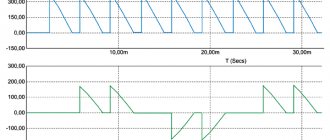
This technique allows you to determine the dynamic difference between the terminals and the chip and, accordingly, the overall level of overvoltage on the chip. Some modules (SEMiX) have direct access to the pins of the Cx, Ex crystals, which allows for the corresponding measurements. The results of such measurements, performed when the short-circuit current is turned off (Fig. 1), show that 4th generation IGBT crystals are especially sensitive to current overload if the voltage on the DC bus approaches the limit values (which can be, for example, in braking mode ). To safely block IGBT 4 in emergency mode (with IC > 2ICnom), it is recommended to use the soft shutdown mode (STO, SSD) with an increased RGoff value (for example, 20 Ohm for a 300-A module). There are also various types of “intelligent” locking, one of which, called IntelliOff, is implemented in the 4th generation SKiiP digital module driver [3].
Rice. 1. Voltage on crystals 450