Home / Devices
Back
Reading time: 5 min
0
833
Today, inverter welding machines are widely used due to their characteristics and applications.
In fact, these devices are quite versatile and can perform a number of functions, from connecting metal parts to starting your car’s engine on a frosty day.
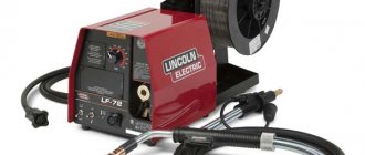
The choice of such devices is huge; there are many models on the market. You can always choose a welding machine with the characteristics you need and at an affordable price.
It is not recommended to save too much when purchasing such a device if you do not want to repair it soon. It is believed that the optimal price for such devices starts somewhere around $100.
However, not everyone agrees to spend that kind of money on a device that will be used several times a year. It’s easier to assemble your own Barmaley welding machine.
- general information
- Principle of operation
- Distinctive features of the assembly Power keys
- Power transformer
- Relay
WELDING INVERTER BARMALEY
Oscillograms for controlling field-effect transistors. I measured it on a ks213b zener diode without power switches, fill factor 43 and frequency 33.
In its version, I replaced the IRG4PC50U power switches with more modern IRGP4063DPBF. I replaced the ks213b zener diode with two 15-volt, 1.3-watt zener diodes connected back-to-back, since the previous ks213b device got a little hot. After replacing the problem immediately disappeared. Everything else remains as in the diagram.
This is an oscillogram of the collector-emitter of the lower switch (according to the diagram). When power is supplied at 310 volts through a 150 watt lamp. The oscilloscope costs 5 volt divisions and 5 µs divisions. through the divisor multiplied by 10.
Then we assemble everything, a gap of 0.1 mm is needed between the halves of the E70 ferrite, and we put a gasket from a regular cash receipt on the outer cores. We pull everything together and glue it together.
When the inverter is connected to the network, charging of the output capacitors begins. The initial charging current is very high, comparable to a short circuit, and can lead to burnout of the diode bridge. Not to mention the fact that for the air conditioners this is also fraught with failure. To avoid such a sharp jump in current at the moment of switching on, capacitor charge limiters are installed. In Barmaley’s circuit, these are 2 resistors of 30 Ohms, with a power of 5 watts each, for a total of 15 Ohms x 10 Watts. The resistor limits the charging current of the capacitors and after charging them, you can supply power directly, bypassing these resistors, which is what the relay does.
In the welding machine according to the Barmaley scheme, the WJ115-1A-12VDC-S relay is used. Relay coil power supply – 12 volt DC, switching load 20 Ampere, 220 Volt AC. In homemade products, the use of 12 Volt, 30 Ampere automotive relays is very common. However, they are not designed for switching currents up to 20 Amps of mains voltage, but, nevertheless, they are cheap, accessible and fully cope with their task.
It is better to use a regular wire-wound resistor as a current-limiting resistor; it will withstand any overload and is cheaper than imported ones. For example, C5-37 V 10 (20 Ohm, 10 Watt, wire). Instead of resistors, you can put current-limiting capacitors in series in the alternating voltage circuit. For example K73-17, 400 Volt, total capacity 5-10 µF. Capacitors are 3 uF, charge a capacitance of 2000 uF in about 5 seconds. The calculation of the capacitor charging current is as follows: 1 µF limits the current at 70 milliamps. It turns out 3 uF at the level of 70x3 = 210 milliamps.
After installing and setting up the circuit on the board, I put everything together. Barmaley passed the tests successfully: he pulled the three and four electrodes calmly. The current limit was set to 165 Amps. Assembled and tested the device: Arcee .
Source
Capacitor charge limiters
Let's talk about capacitor charge limiters. In the original circuit, Barmaley used two 30 Ohm resistors with a power of 5 W.
They cope with their function perfectly, so we decided not to change them. Thanks to the relay, power can be supplied directly after charging.
When we turn on the Barmaley apparatus for the first time, a sharp current jump will occur, and a high current strength can cause the capacitors and diode bridge to burn out. The recommended resistors can just prevent this problem.
Relay
Now a few words about the relay. We also do not recommend changing this part, leaving the option present in the original diagram. This relay is type WJ115-1A-12VDC-S.
The welding coil of the Barmaley is powered by 12 V DC, its switched load is about 20 A, powered by 220 V AC.
This relay copes with its task perfectly, and its low price and wide distribution in the retail chain make it an excellent choice.
We make Barmaley's welding inverter. Part 1.
Administrator of welding forums
Group: Moderators Messages: 1133 Registration: 17.8.2004 From: Tolyatti User No.: 1622
All these schemes have the same basis. Therefore, to create a power source for a PLASMATRON, a very attractive option is to manufacture an inverter according to Barmaley’s scheme and, after a successful launch, convert it into a plasmatron, based on Yuri Krovyakov’s scheme.
I would like to invite forum visitors to take part in the On-Line project - Making a Barmaley inverter. Together we will think about the layout, draw the necessary printed circuit boards, and think about what and how best to do it. Let's listen to a bunch of crazy ideas and use the process of elimination to choose what suits us. So let’s put together a popular inverter, which has long won trust on the Master City forum - “Has anyone tried to make a welder?”
Well, the final point will be to convert this inverter into a power source for plasma, but that will come later.
Look at the diagrams, digest the idea, and for now I’ll think about where to start.
Administrator of welding forums
Group: Moderators Messages: 1133 Registration: 17.8.2004 From: Tolyatti User No.: 1622
I agree, before you decide to do something, you always want to know how it will end. And it will not end with a stupid connection to the network (although the circuit is so good and with a reserve that a correctly reproduced welder can be safely connected to the network, without any checks).
Quote from the forum “Has anyone tried to make a welder?”
This is all very approximate; a creative approach is needed. A possible feature is that the ballast is not mentioned at all, everything is through the short circuit.
Administrator of welding forums
Group: Moderators Messages: 1133 Registration: 17.8.2004 From: Tolyatti User No.: 1622
All these components put together will ultimately produce a welding inverter.
It will be very useful for theory lovers to read the articles by Alexander Goncharov “Primary school for building pulsed DC/DC converters” - 5 parts. These articles are a kind of Bible of pulse circuit design. They describe in accessible language the processes occurring in inverters during their operation.
Administrator of welding forums
Group: Moderators Messages: 1133 Registration: 17.8.2004 From: Tolyatti User No.: 1622
My thoughts on the first point (Input rectifier with capacitors):
Diode BRIDGE: Diode bridge brands are KBPC3510, KBPC5010 (35 and 50 Amperes, respectively, 1000 Volts). Powerful, cheap, widespread. In Runet (where, I don’t remember) I read an opinion that 35 Amp output legs heat up less than those of 50 Amp ones. What this is connected with and whether it corresponds to reality, I don’t know. I would put the KBPC5010 at about $2.
How to assemble a homemade Barmaley inverter welding machine?
Reading time: 10 minutes
Nowadays, an inverter welding machine has many application scenarios: from a device for joining metal parts to a starting-charger for trouble-free engine starting on a frosty day. Inverters have truly changed the world and turned from an expensive toy into a full-fledged tool that is accessible to everyone. Nowadays, an inverter can be found both in the workshop of a professional craftsman and in the garage of a novice welder. And this is facilitated by the large assortment in the store. There are devices for sale for every taste and budget.
However, we do not recommend buying the cheapest inverters. In our opinion, the starting level is $100 and above. This will be a rational purchase, and the device will not require immediate repairs. But what if the amount of $100 turned out to be too much for you, and you are not ready to spend half your salary on an inverter that you will use a couple of times a year? In such a situation, you can assemble a welding inverter with your own hands.
There are many diagrams, instructions and videos for assembling an inexpensive inverter. They are not easy to figure out right away, even if you are an experienced craftsman and understand electronics. Therefore, we offer a time-tested option that has been tested by many welders - a homemade Barmaley inverter. Barmaley’s homemade inverter welding machine has been known for many years; many welders have tried it and were satisfied.
In this article, we will describe in detail what components we use to assemble this inverter, provide a diagram, talk about the operating principle and draw attention to the main features. This article is not a step-by-step guide. We simply share experiences from ourselves and other masters.
Power Electronics
Links to descriptions of homemade inverter welding sources published on the website https://valvolodin.narod.ru1.
External views of Barmaley’s welder - https://valvolodin.narod.ru/schems/Barmaley2.zip2. Inverter welding source from Alexander Bolshakov (see diagrams in the Splan program) - https://valvolodin.narod.ru/schems/2006_10_31.rar3. Photos of some components of the inverter welding source from Alexander Bolshakov - https://valvolodin.narod.ru/schems/Foto_Svarki.rar4. Inverter source based on a single-transistor single-cycle forward converter (simpler than Barmaley’s welder) - https://valvolodin.narod.ru/articles/fiksatyi.html5. Description of a homemade thyristor resonant welding source - https://valvolodin.narod.ru/articles/tir_inv.pdf6. A detailed description of a welding source based on the Colt-1300 (my article in Radio No. 4 magazine for 2007 in a paper clip) - https://valvolodin.narod.ru/articles/Kolt.pdf7. Materials on the RytmArc welding source - https://valvolodin.narod.ru/rytmarc.html8. Welder from the Polish magazine Elektronika Praktyczna 11.12 for 1999 - https://valvolodin.narod.ru/articles/amat_spawarka.pdf9. Homemade welder with a bridge inverter. Article in Czech - https://valvolodin.narod.ru/articles/invertor_popis.pdf10. Homemade welder from the city of Brno (based on Cemont) - https://valvolodin.narod.ru/articles/invertor_brno.zip11. Printed circuit boards in Eagle format for a welder from the Polish magazine Elektronika dla Wszystkich 1-2 for 2009 (a version of Barmaley’s welder) - https://valvolodin.narod.ru/articles/Spawarka.rar12. Description, diagram, printed circuit boards in laoyt5 format, as well as external views of a welding source with an output current of 5-120A - https://valvolodin.narod.ru/articles/rw4hdl.pdf, https://valvolodin.narod.ru/articles /rw4hdl.rar13. Welding source based on the inverter of Vadim Negulyaev - https://valvolodin.narod.ru/articles/LeeOn23.pdf14. Welding machine for current 240A - https://valvolodin.narod.ru/articles/svarochnik.rar15. Diagram of an inverter welding machine with a synchronous rectifier and an output current of 5-120A - https://valvolodin.narod.ru/articles/swarkainwerter.JPG16. Archive with a circuit diagram and external views of a homemade inverter welding source with a regenerative snubber - https://valvol.qrz.ru/articles/svar.rar17. Circuits and printed circuit boards of a welder for a current of 250 amperes - https://valvol.qrz.ru/articles/svarochnik1.rar18. Diagram, description and printed circuit board of a welding source built on the basis of a phase-controlled bridge on the UC3875 microcircuit - https://valvolodin.narod.ru/articles/arcweld_UC3875.pdf19. Diagram and description of the next welding source from RW4HDL - https://valvolodin.narod.ru/articles/svarochnik2.rar20. How to make a reliable and high-quality inverter - https://valvolodin.narod.ru/articles/taranenko.zipAdded by the administration Continuation of the topic Making a welder, the end of which is located on the old forum
Transferring messages from the intermediate forum:
MisterYes, so the point is that for transistors operating in hard switch mode, there are 2 types of losses: when switching and losses in the open channel. And, it is absolutely clear that their value is determined by the switching frequency and the duty cycle of the signal. I'm considering a full bridge. If we conventionally assume a duty cycle of 1/2 (roughly speaking, because it takes time for the first pair of transistors to close before the second pair begins to open - otherwise a through current will flow), then in fact the losses during pre-switching and losses in the open channel are as follows: would “pull” each other in the frequency domain. That is, we can conditionally calculate the “golden mean” where they would intersect: as you can see, the intersection point is at a frequency of 116 KHz, however, the calculation was made for a slightly different circuit and for other keys, but the idea in principle should be the same?
valvolodin
Quote:
... in fact, losses during pre-switching and losses in the open channel seem to “tug” each other in the frequency domain. That is, we can conditionally calculate the “golden mean” where they would intersect...
Everything is fine, but for some reason in this graph the conductivity losses decrease with increasing frequency!!! In fact, conduction losses are stable or even increase with increasing frequency.
Multik
Quote:
Yes, so - the fact is that for transistors operating in hard switch mode, there are 2 types of losses: when switching and losses in the open channel... I am considering a full bridge... the calculation was made for a slightly different circuit and for other switches, but the idea is in principle should it be the same?
No, that's not the idea. Valentin has already explained. But I’m interested in something else. Where are you going to apply the results of research on transistors operating in hard switch mode? In a real circuit, this switch is not so hard. If IGBT transistors are used, the turn-on will be soft due to the presence of leakage inductance in the transformer. If MOS, then the shutdown will not be hard due to the high output capacitance, and is determined by the current through the transistor at the moment of shutdown. That is, you need to know the parameters of a specific circuit and calculate for a specific case. Today it’s easier to make Soft, and not worry about calculations. I remember that all our depots were filled with steam locomotives, but we still had to throw them away. The efficiency did its job.
Mister
Multik, I don’t mind that it’s soft, I just called it that. Regarding the loss of conductivity - here, in theory, if the transistor switches more often, then the time it spends in saturation per unit time will decrease, that is, according to Watt's law, this share of power will also decrease. Another thing, as I already wrote, is that the calculation was not carried out specifically for this case; in my opinion, the heating of the transistor was not even taken into account
Now I’m going to study the datasheet, in which the entire algorithm is given, it turns out there is some other type of loss there...
GYGY
Mister according to your bridge diagram. 1.Why such bells and whistles with the buildup?2. look at the activation of the signal trance - all 4 keys will open at the same time and there will be a bang.3. a bridge in the output rectifier is an extra 200-300 W of heat (in relation to welding power) And what experiments with frequency do you plan to conduct (filling chirp pulses)?
Mister
1. Because I'm afraid that the drivers might be burned. 2. How can all 4 mosfets open at the same time, if the TL494 has a plus applied to the OTC input and both emitters are raised from the ground by resistors, and the driver inputs are connected crosswise, take a closer look again, the circuit is, in principle, classic! 3. I agree, especially since with increasing frequency this figure can reach large values 4. And why did no one write that there is an inaccuracy in the diagram: the current TP3 should be in front of the main transformer. The experiments are as follows: I calculate and make a couple of transformers and chokes for different frequencies up to 100KHz, I compare the losses on the switches, transformer, inductor and rectifier (as for the latter, 100% will be worse), in short - a pure experiment... Regarding gate control, there is generally this idea: connect the control transformer directly to the driver outputs, something like this: where the field switches are already powerful output transistors (or IGBTs instead), which are connected to the rectified mains voltage, that is, you again need 2 drivers and 4 switches to get a full bridge, how do you like this idea?
GYGY
Mister, unfortunately the picture from the Courageous Penzyuks website has disappeared. Therefore, from memory, I meant that in the circuit the gates of all powerful switches are connected to the beginnings of the secondary windings (despite the crossings when drawing), and therefore they will open and close synchronously.
Mister
Oh, yes, I understood what was meant, the drivers have common-mode signals at the inputs, because their inputs are switched crosswise, and in the output stage (on the igbt) there is only one control signal, well, it’s enough to change the 2 lower windings backwards.
Or maybe it’s to such and such a mother, connect the IGBT gates directly to the driver outputs
By the way, there’s a more serious problem here - I tried to find the ETD59, but I couldn’t find anything, I’ll have to raid the local dumpsters in search of TVs.
GYGY
Quote:
By the way, there’s a more serious problem here - I tried to find the ETD59, but I couldn’t find anything, I’ll have to raid the local dumpsters in search of TVs.
if you have a pure experiment, then why is ETD59 necessary? And other options are Sh (E), ring (For example, Bolshakov stirred up a double sausage, on modest rings there are 10 kilowatts)
Mister
In general, I have some kind of ring: outer diameter 10 cm, width 2.5 cm, height 3.5 cm (or vice versa - I don’t remember), but I don’t know what kind of ferrite it is (there were no markings on it), but I think that its permeability is too small, of course, you can wind a few turns and measure the inductance and then recalculate the permeability... I have another question: please tell me an ultra-fast diode for topswitch for 5-10A, and a voltage of up to 50V in the TO220-J11 case so that the 1st and the 2nd legs were a CATHODE, if, of course, such exist in nature, because according to the DACPOL catalog for power components, there are ultra-fast diodes in the TO220-J11 package, but they have anode terminals.
Last edited by valvol on 13-07, 20:27, edited 7 times in total.
valvol.ru
general information
The Barmaley inverter is a famous welding machine that has been known to home craftsmen for more than 15 years. It got its name thanks to a user under the nickname Barmaley, who proposed the design of this device on one of the thematic forums. The circuit diagram of the welding machine is simple and clear. At the same time, many components can be replaced with others, making production more expensive or cheaper. The main feature of the Barmaley inverter is its low price and functionality. It is reliable and repairable. This option will appeal to craftsmen who are not willing to pay $100 or more for a factory-made device from a store.
Typical circuit and principle of operation of the inverter
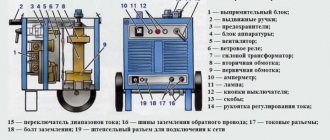
This is the main role of transformer T3. Read more. To power the microcircuits and elements located on the control board, a 15-volt integrated stabilizer - LMA - is used. According to the principle of operation, it is very similar to switching power supplies, for example, AT and ATX computer power supplies. Checking functionality After assembly and debugging work, the functionality of the welding machine is checked. The switch module is represented by four transistors in each of the four groups.
The additional arrangement of 0.15 µF capacitors allows excess power to be dumped back into the circuit.
At the same time, the principle of operation of the latter remains unchanged.
The transformer steps down the current to a voltage level equal to V.
This is where the rectifier comes into play, ensuring that the incoming current has constant parameters.
The resistor resistance is 47 ohms. Open circuit voltage 62 V. TWO in ONE. WELDING + INDUCTION FURNACE. Short review. Welding machine - heater 2 in 1
Principle of operation
An inverter assembled according to Barmaley’s scheme does not differ in its operating principle. It is powered by a single-phase network with a voltage of 220 V. The resulting current is rectified and then smoothed using capacitors. At this stage the current is constant. After smoothing, it is fed to transistor switches. They convert direct current into alternating current.
Alternating current is supplied to the transformer. It is ferrite, since high-frequency current is used, because of this it is possible to use a transformer of smaller dimensions and, accordingly, do not use metal. After the transformer, the current is supplied to a step-down transformer. Behind them comes a rectifier and a choke.
As you can see, the operating principle is almost identical to a regular factory inverter from a store. However, the beauty of Barmaley’s scheme is precisely that such a homemade inverter can be modified and modified many times. That's what we will do in this article. There are many modifications of this famous device. We settled on the most inexpensive and at the same time functional one.
It's winter and I don't want to go outside. Up to -25 degrees however. But it's sunny every day. Cool. The house is warm and the sun is shining through the window. I slowly began to assemble the welding inverter . to assemble a welding inverter with my own hands for a long time, but I never had the time. In winter, there is more free time and therefore more freedom for creativity. Prices for welding inverters in city stores are very decent. I need a simple device for occasional country work. There is an option to buy the cheapest Chinese device, but it will be much worse than a homemade inverter for the same money. Yes, and I love collecting things with my own hands. At first I wanted to make a transformer welder, but I couldn’t find a free magnetic circuit for making a transformer, and I don’t want to buy it at all because it costs a lot, and what is it worth to actually assemble a junk welder? No, that won't work.
I took a closer look at modern welding inverters, and it’s actually not all that complicated. The overall weight of the structure is lighter. And the load of inverters on the already “sagging” country electrical network is lower. I took as a basis the circuit of a welding inverter of the resonant bridge type of Mr. Negulyaev, which was popularly called a negligent.
His two books “Welding inverter is simple” and “Welding inverter is simple Part 2” in PDF format can be easily downloaded to the Internet. Enter the query in a search engine: “Welding inverter is just Negulyaev” or something like that.
Click on the diagram to view it in full size.
I will not write here the same thing that you can already read in the books mentioned above. Therefore, look in the book for details. On the Internet, many experts criticize Negulyaev and his invention. Basically it all comes down to what can be done cooler. I don't need anything cooler. Like, for example, it’s better to use special modern drivers for IGBTs. And I don't want to pay extra money for them. So this inverter itself is not resonant, but quasi-resonant, or maybe still resonant? In any case, the scheme works. Reliable enough. Allows you to remove 200 - 250 amperes.
I started collecting. I made a list of parts and went shopping. It turned out that not everything is so simple and even radio component stores in St. Petersburg do not have most of the necessary parts. IGBT IRG4PC50UD transistors for the bridge in Mikronik. Simitron has it, but it is sold only to legal entities. In Megaelectronics it is also bad and at best only on order. Chip and Dip has it, but as always in the best traditions of the store at triple the price. It's the same story with the 150EBU04 and especially with ferrite .
I spent a long time looking for components in stores. With the Chinese (order online with free delivery), in addition to having everything you need, I am also pleased with the price. Even when ordering from sellers with paid delivery, it still turns out much cheaper than with us on the Internet or in a real store. I thought why would I source components to order. Wait two weeks for these orders. Then go and pick them up at different places. Overpay. In China I will get everything much cheaper (at least what I wanted) and the package will arrive almost in my hands (the post office is a three-minute walk from my house).
The parcel arrived quite quickly. Everything was very well packaged and arrived safe and sound. While I was waiting for this parcel, I soldered a generator from my old supplies. This part of the diagram.
All that remained was to plug the UC3825N chip into the crib. This is what happened.
Then I wound the throttle Dr.3. for a voltage multiplier, 15 turns of mounting wire are preferably 1 sq. mm. on a ferrite ring 28x16x9 2000HM1. I wound a homemade one made of two 0.5 sq.m. ball screws. mm. The factory insulation was removed and they were twisted together. Then the PVC insulation was restored with electrical tape. After winding, the winding is varnished.
The manufacture of transformer Tr.3 took more time, since the winding refused to fit. It seems that the wire was used with a smaller diameter than the author of the book that has already been mentioned more than once.
We managed to wind 26 turns on a 28x16x9 2000HM1 ferrite ring, which is basically enough (25-30 turns are needed). I used what was at hand, namely a 6-wire CQR, removing the general insulation.
Conveniently, each winding has its own color. I still recommend using MGTF; its insulation is more reliable.
The resonant capacitor was assembled from six domestic capacitors K78-2 0.15 μF / 1000V. with a total capacity of 0.225 µF / 2000 V. This is a critical unit and cannot be sculpted from just anything. The photo of the composite capacitor shows one 150 KiloOhm resistor; later another one of the same type was added. (Each in parallel with its own line of capacitors.)
A 5 µF 450V input capacitor specifically for alternating current will not be small in size. It has a convenient bolt mount.
It is recommended to put ferrite rings (although the book doesn’t say anything about this) on the terminals connected to the output diodes D3 and D5 150EBU04 of the output transformer Tr.1 in order to eliminate emissions that can kill expensive plugs (D3 and D5 150EBU04).
Also, in parallel with them (D3 and D5 150EBU04), it would not hurt to install transils (protective diode) of type 1.5KE350CA.
If it suddenly happens that your fuckers burn, don’t rush to throw them away. The fact is that the 150ebu04 is a composite diode and consists of two parallel crystals of 75 amperes each.
It often happens that only one of them burns out. It is necessary to saw through the middle of the terminal on which there are teeth for soldering. It is necessary to saw until you go a millimeter deeper into the component body itself. As a result, if you are lucky, you will get a fairly powerful 75 ampere diode.
The bridge itself of the welding inverter on four IGBT transistors IRG4PC50UD turned out like this.
The transistors are located on the other side of the board; a radiator with cooler cooling (fan) will be attached to them. The tracks are additionally reinforced with copper conductor of millimeter cross-section.
For the manufacture of power transformer Tr.1 and resonant choke Dr.1 I use Epcos ferrite core E65 No. 87 (approximate domestic analogue 20x28 2200HMC). One core per transformer and per inductor. The output of the welding inverter will draw 160 Amps.
It came to me in a package in the same packaging as in the photo.
I came across the thermostat by accident when I went to a gas equipment store. In which they sold all sorts of gas boilers and simple water heaters. They also sold spare parts for this very gas equipment. the KSD301 thermal relay is lying on the display case , exactly 90 degrees as I wanted. The current reserve is much more than I need. If I'm not mistaken, it cost 30 rubles apiece, but definitely no more.
I bought two pieces. I will put one on a radiator with IGBT transistors IRG4PC50UD, and the other on a radiator with 150EBU04 output power diodes. The thermorelays themselves can be connected to the break in the wire through which the control signal goes to the 12V 30A input relay.
I already had a 30A 12V input relay in stock. For those who don’t have it, to save money, I advise you to purchase it in stores for domestic cars. There, a relay with such characteristics will cost an order of magnitude cheaper than in a radio components store. For example, I was recently in an auto shop for GAZ cars and saw a suitable Russian-made relay for only 50 rubles.
You can buy radio components for a welding inverter in China via the Internet with free delivery. Almost everything is there:
- IGBT IRG4PC50UD transistor.
- Power diode 150EBU04.
- Protection diode 1.5KE350CA.
- 85 degree thermal relay KSD301.
- Chip UC3825N.
The continuation of the story about a homemade welding inverter is already here.
Assembly Features
In this article we will not explain in detail each step: what, where and why. Because on the Internet everything has already been said before us and there are even visual videos. We will talk about the features of the assembly and those components that we have slightly modified to obtain the characteristics we need. The material was created based on the experience of one of the masters.
Power keys
Let's start with power keys. In the Barmaley scheme, it is recommended to use keys of the IRG4PC50U type. But we replaced them with IRGP4063DPBF keys, they are more modern and reliable. Also, instead of a KS213B zener diode, we used two back-to-back zener diodes of 15 Volts each. Power - 1.3 W. The replacement is due to the fact that KS213B can get very hot. No more changes. We took the remaining components from the diagram.
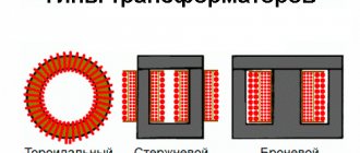
Power transformer
Now about the power transformer. We wound it on a ready-made core type E70/33/32 (or B66371-G-X187, N87) from the manufacturer EPCOS. We see no reason to make the core ourselves, since a ready-made one is not that expensive. They wound it like this: first they wound half of the turns for the primary winding, then they wound the entire secondary winding, and after that they wound the second half of the turns on the primary winding.
The same wires were used on the primary and secondary windings. We chose a diameter of 0.6 mm. 18 turns were wound on the primary winding. 9 turns for the first row and 9 turns for the second. Don't forget to insulate between layers. For insulation, you can use regular cash register paper. The option is inexpensive and effective. Also, each layer must be impregnated with epoxy resin.
If desired, the primary winding can be wound with wires with a diameter of 1.2 mm or 0.4 mm. Then you will have to make either more or fewer turns. And carry out additional calculations. But if you are assembling a device for the first time, then it is better to use our initial recommendations.
We also recommend wrapping both the primary and the secondary with masking (construction) tape. This is necessary for additional insulation. When winding, mark the ends of the wires. This will make it easier for you to put everything together. It will also be easier for you to carry out phasing. And if phasing is done incorrectly, then your device will use only 50% of its potential.
When assembling, take into account the micro-gap between the core halves. From the outer cores you need to put a gasket made from the same cash paper. Everything needs to be tightly pulled and glued. Additionally, this entire structure can be spray painted and varnished on top.
Capacitor charge limiters
Let's move on to capacitor charge limiters. The Barmaley device uses two resistors by default, 30 Ohms each, with a power of 5 W. We did not change these resistors; they do an excellent job of charging capacitors. After charging, power can be supplied directly thanks to the relay.
Comparison of homemade inverter and transformer
The predecessor of the welding inverter is the welding transformer.
Welding transformer
Many such devices were used in pipe welding. They have both advantages and disadvantages compared to an inverter:
- It is much easier to make a welding transformer; for this you need a minimum of knowledge in electrical engineering and simple calculations
- A transformer of the same power weighs 3-5 times more than an inverter.
- The transformer contains more expensive copper, but in terms of manufacturing cost it is still cheaper than an inverter.
- There are problems with current regulation - regulation is carried out by changing the voltage of the transformer.
- When designing a transformer, you can easily exceed safe voltage values, and the electrical device will become dangerous for the welder.
- Likewise, it is possible to make mistakes when assembling an inverter, and it can also be dangerous. But if everything is done correctly, it is safer than a transformer, which, due to problems with regulation, may experience transitions beyond the permissible voltage limits.
- A good welding transformer is calculated according to the so-called. "voltage and current curve" to obtain acceptable output parameters
- The inverter allows you to regulate the current within a wider range. The transformer allows you to work only with a limited set of electrodes.
- The transformer is also larger in size than the inverter.
- The transformer has a lower efficiency and heats up more.
- It is much more difficult to ignite a welding arc from a transformer than from even the worst inverter - the electrode sticks.
In general, if you do not want to understand electronics, we can recommend making a welding transformer instead of an inverter. In any case, this is the cheapest option, although not the most convenient.
Safety precautions
Most people will probably skip this section, but we'll still cover some basic safety rules. Because there are craftsmen who hope for a miracle when they assemble a device in violation of all norms. But sometimes a miracle doesn’t happen...
First of all, do not assemble or repair the device in a room with high humidity. And under no circumstances touch the regulators, the power plug, or the device itself if your hands are wet. This is an elementary rule that many people neglect and then greatly regret it. You should know that 100 milliamps is already enough to cause death. And the welding machine is capable of generating much greater value. And in the best case, everything will end in fire. You can think of the worst case scenario on your own.
By the way, about the fire. If by an unfortunate accident your device catches fire, do not dare to extinguish it and surrounding things with water. This is the case when the device is plugged in and you do not have the opportunity to turn it off. Therefore, have a small dry powder or carbon dioxide fire extinguisher nearby. But if you have the opportunity to quickly turn off everything, then it is better to do this and then put out the fire.
If when you first turn on the device you see that it is sparking or smoking, then naturally turn it off and do not use it. It is for this reason that you should not immediately pack all the “stuffing” into the case. Do all the tests first. Also ground the device, do not ignore this step.
Rarely does anyone think about the tool they use. But it also needs to be isolated. It doesn’t matter what you have in your arsenal: pliers, screwdrivers or wire cutters. All handles must be insulated with non-conductive material. Most tools have isolation by default. But if you use, say, ordinary metal wire cutters, then at least wrap the handles with electrical tape.
And do not use cracked/bursted/old tools. They rarely cause sad consequences, but there have been cases. Don't tempt fate. Follow these simple rules and take care of your health. And if your neighbor has been repairing electrical appliances for ten years and does not follow any of the rules, this does not mean that you should do the same.