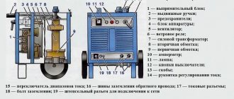
A conductor is a material with low resistance through which electric current is transmitted. Due to the fact that the conductor resistance is small, the unproductive losses of electricity are insignificant. This is a common practice in constructing electrical circuits. But other problems also happen, just the opposite. That is, the conductor resistance must be increased to the maximum possible value.
The need is most often dictated by inflated current values. Their value must be adjusted to certain requirements, which are less than the nominal ones. For such purposes, the ballast was invented. It speeds up the welding process and makes it easier. A ballast rheostat is a special device designed to regulate the current during welding.
How it works?
At its core, it is a ballast rheostat - a special device for generating increased resistance for welding electricity. This rheostat is distinguished by its simplicity. It is built into many advanced and expensive models of welding machines, and can also be purchased separately.
In addition, you can build a ballast yourself without any problems. It should be noted that every self-respecting welding master has such a device in his storage room.
According to the principle of its operation, the welding ballast is a point of obstacle in the path of the movement of electric current; it is a “point” of high resistance. From an external point of view, it looks like a complex thick spring.
This spring is always equipped with a movable contact, which, when moving along the spring, changes the length of the path that the current passes through the ballast.
This device cannot boast of a particular variety of models.
There are some differences, they are determined by the following criteria:
In fact, it turns out as follows: without a ballast rheostat, the current would have a force of 250 A. If you connect a ballast to this circuit, the electric flow will begin to lose strength and would have only 10 A at the output.
Of course, the regulator can change the length of the spiral path along which the flow passes. The losses in this case would be different.
How to make a ballast with your own hands?
The first step is to find a suitable metal wire. It could be, for example, copper. Additionally, you will need a cylindrical shape, for example, a pipe and an ammeter. You need to think about what to make the moving contact from; it could be a wire.
The straight wire needs to be turned into a tight spring. To do this, it is wound onto a cylindrical shape, trying to place the turns as close to each other as possible. The end of the twisted wire must be connected to the wire for current. We also attach a moving contact.
The next step is very important: you need to check the operation of the new rheostat with help. Ammeter. The fact is that a homemade ballast for a welding machine is not as accurate as factory models.
The next caveat is that our rheostat is not equipped with a housing, so compliance with safety regulations becomes even more mandatory.
Classification
Ballasts are almost the same in their operating principle or design, but may have a number of features. The range of values that we can choose to set the desired resistance will depend on them. So, ballasts differ in the following parameters:
- Spring length. Everything is simple here - the longer the spring, the longer it takes for the current to pass through all the turns.
- Metal. Ballasts are made of various metals, each of which has its own resistance coefficient. The more powerful and serious the welding machine, the more carefully the ballast material is selected.
- Thickness. Both individual turns and the entire spring as a whole. This determines how strong the resistance indicator will be. The thickness indicator is closely related to the length indicator.
Ballast rheostat settings
The main thing in a high-quality welding process is stable performance of the electric arc, or rather, its current-voltage characteristics. Modern inverters cope well with this requirement.
Marking of ballast rheostat.
This is done by converting the current into two stages and switching the inverter itself. All other welding machines cannot boast of such characteristics. Therefore, a ballast rheostat must be present next to them.
It is designed for stepwise control of arc operation and compensation of the current component during recharge from the transformer. Nichrome wire in the parallel connection circuit is the main component element. It is important that each section of the rheostat is connected to the network independently, using a switch.
Such a rheostat has only two working functions:
The performance and overall efficiency of a ballast rheostat directly depend on the number of turns or sections of the spiral. After all, each of them is an element of a chain that is broken using a switch.
The circuit is serial, and the connection of sections is parallel. This combination gives an excellent result: periodically connecting each of the elements to the work in order to regulate the voltage in the welding machine.
The connection of the rheostat to the welding circuit must be in series with the power source.
Control buttons are always located on the outer wall of the protective metal case. The most advanced rheostatic models have internal fans that cool the device’s elements while operating at high current levels.
If there are no fans, you must ensure that several rheostats are switched on in series.
The most popular line of ballast rheostats on the market under the abbreviation RB: there are only five options for different current values - its range - minimum and maximum values.
We offer an easy walk through the most popular models to get acquainted with their technical characteristics in more detail:
RB-302
An excellent device as a companion to welding units for adjusting the current strength in semi-automatic or manual welding processes. Works in parallel with welding rectifiers and generators.
This version is designed for a power supply range of 27 - 30 V with a maximum maximum of 70 A and a minimum drop of 30 A.
The rheostat is equipped with an air cooling system. It has a good PV indicator - the on-time is 60%. This means that the welding duration should not exceed 10 minutes. Otherwise, the PV must be reduced.
In this device, the welding current adjustment is represented by six steps, which are cyclically turned on and off.
The structural elements are made of the most modern materials: the insulation, for example, is made of ceramic profiled plates, and the plateau is formed from special heat-resistant fechral wires.
RB-302U2
This model is a type of mother rheostat for operation in conditions of high humidity or harsh ultraviolet radiation. As a result, you can work with it outdoors in conditions unfavorable for conventional equipment.
RB-306
This model is more serious: it does not overheat and is much more accurate in regulating the welding power supply than the RB-302. The rheostat is equipped with an improved cooling system: there are more blind holes in the body, so the blowing of the resistors is intense and efficient.
Electrical circuit of the ballast.
All resistance elements are arranged in a modular system. This arrangement makes diagnosing and replacing elements much easier and more accurate. The range of current values is much wider, and the indicators can be adjusted with much greater accuracy.
These are special Ballast Rheostat Blocks. They are assembled from RB-306 elements for cutting metals using the electric arc method. This is an excellent solution for controlling the welding current from the rectifier in automatic machines.
Popular models
The line of ballasts marked “RB” are 5- and 6-position options with value increments from 5 to 10 amperes. The numerical designation corresponds to the range from the minimum to maximum value of the welding current.
RB-302
For semi-automatic and manual welding in modes from 30 A to 70 A, it is recommended to connect this model of welding rheostat to transformers, rectifiers, and generators. The duration of activation is at least 10 minutes, this time is enough for welding in the garage or at home.
Rheostat with a 6-position switch, works with equipment connected to a single-phase 220 V and three-phase 380 V network. The housing and internal elements are made of modern materials, metal elements are fechral, support plates are ceramic.
RB-306
This is a resistor model with an improved cooling system. The resistances are modular, made of 3 mm fechral wire, they are easier to change. The first branch is a tubular heater. The current adjustment is quite accurate. The rheostat is combined with cutters and high-power cooking equipment. On the basis of RB-306, modifications of the BBR for multi-station welding are assembled.
Rules for working with ballast rheostats
Despite the simplicity of design and use, ballast rheostats require certain operating rules to be followed:
If the rheostats overheat, you need to connect several rheostats to the arc - in sequential order. Well, if the welding current is less, then the resistance should be increased.
When working with aluminum, for example, the alternating current needs to be adjusted within very small limits, only up to 20%. In this case, incomplete compensation of the direct current component occurs.
If we are talking about full compensation, then you need to use devices of the UKDN or UDGU brands, which are equipped with capacitor banks.
Source
Ballast rheostat
Ballast rheostat is a device that is used to regulate the current level when performing welding work. Its device is a set of several resistance elements. They are made of special constantan wire. This allows you to achieve maximum ohmic resistance. This unit is connected to the welding circuit using special switches.
Its connection should be made in series in a circuit, while the resistance level is adjusted by turning the working sections on and off. Welding work with a rheostat connected can be performed with current in steps of 5-10A.
Device
The design of the ballast rheostat is quite simple: it consists of working sections placed in the body of the device. A resistance switch is installed on each section, with which you can turn the sections on and off. The device also includes terminals for connecting to the welding circuit.
Each section is a tape made of a special metal, for which constantan or nichrome wire is usually used. Also, most machines are equipped with a switching unit that allows you to adjust the welding range to the required level.
All controls, including the power unit and toggle switches, are usually located on one panel of the device.
It should be noted that most modern rheostat models are equipped with a cooler system for cooling the device, represented by built-in fans. This system helps to avoid overheating during prolonged operation of the device. This allows you to operate at high currents without the need to connect an additional rheostat.
Ballast rheostat circuit
It should be noted that when overloaded, this device is characterized by significant heating, which occurs at a current strength of 225 A. Therefore, it is recommended, in order to avoid embarrassment and malfunctions, to include two rheostats in the circuit.
Operating principle and design
So how does a ballast work? In simple terms, the current that flows unhindered through the circuit encounters high resistance at a certain point, due to which it loses its magnitude. The “culprit” of high resistance is precisely the ballast connected to the circuit.
Visually, the ballast for a welding machine is a large spring with many thick turns. This spring creates ballast resistance. A regulator is connected to the spring, with which you can change the resistance value to more or less, and therefore change the current strength. The regulator is a movable contact that is moved along and thereby reduces or increases the length of current flow through the ballast. Ballasts are an integral part of any experienced welder's arsenal.
Purpose
The purpose of the ballast rheostat is quite simple, but in some cases it is impossible to perform welding work without its function. This device is necessary to regulate the current strength in the required range using toggle switches and compensation of the constant component. This effect occurs in cases where welding work is performed from a transformer.
The efficiency and cost of the rheostat depends on the number of sections, with the help of each of which you can adjust the resistance level in a certain way. The switch allows you to mechanically break the chain.
Parallel connection of sections allows you to optimally combine the work of each, which is very important for the welding machine that performs the corresponding work. The current adjustment step is usually in the range from 5 to 10 A.
Today, we should highlight a line of the most popular types of rheostats called RB. The marking of each device indicates the current range within which welding work can be performed.
Ballast rheostat RB-302
RB-302 is one of the most common types of rheostats, the technical characteristics of which allow it to operate at currents from 10 to 315 A. This device can be used when performing various types of welding work, including manual operations or when working with semi-automatic devices. It can be used in conjunction with rectifiers and generators.
Ballast rheostat RB-302
RB-302 is equipped with an air cooling system, which can significantly expand the scope of its application. The device operates from a 380 V network. It can be used when connected to various types of power sources, except for some types of transformers. When working with them, it is recommended to connect several rheostats in parallel.
This device, like most analogues, allows operation in two ranges, 5 and 10 A. It consists of six working sections, the adjustment of which is carried out using special contact knives. The diameter of the wire used in the sections is 2.2 mm. The insulation consists of ceramic plates.
When using this device, periodic monitoring should be carried out, which is performed by measuring the actual insulation resistance and comparing it with the housing indicators.
Ballast rheostat RB-306
RB-306 is the next generation from the well-known line of rheostats. This type is intended to be a solution to problems that often arise when using RB-302. Among them are frequent breakdowns of resistors and overheating of the device itself. When developing a new model, all the shortcomings of the previous device were corrected.
The new case has been designed with an increased number of holes for faster cooling. The wire of the sections is made of fechral.
The improved arrangement of working elements allows you to quickly and easily check and replace them.
Ballast rheostat RB-306
This device allows you to cut metal. To do this, you need to assemble a block of the above rheostats, which is used together with a rectifier.
To use the rheostat effectively, you must adhere to certain rules, among which are compliance with climatic conditions, cleanliness of the working area, as well as constant diagnostics of the device for serviceability. This is best done in special service laboratories.
Source
Ballast rheostat. Setting the welding current
The basis for a stable welding process is maintaining the required current-voltage characteristics of the arc discharge. In inverter welding installations, this is achieved due to a two-stage conversion of the operating current and a certain frequency of turning the device on and off. For other cases, a ballast rheostat must be present in the circuit.
Purpose and design of the ballast rheostat
To form a steeply falling current-voltage characteristic of the operating current during welding, the ballast rheostat must perform two functions: discretely regulate the current strength, and compensate for its constant component, which occurs when the welding station is powered from a transformer.
The effectiveness of a ballast rheostat is determined by the number of its working sections, each of which is a serial electrical circuit consisting of a resistor with a certain resistance and a switch that mechanically breaks this circuit. The sections are connected in parallel, which creates the best opportunities for the combined inclusion of each of them in the work. As a result, the current can be adjusted in steps of 5...10 A, which in most cases is quite sufficient. The ballast rheostat is connected in series with the current source into the common circuit of the welding station.
Structurally, the ballast rheostat is a unit consisting of:
All controls are displayed on one of the external panels of the case. In the most modern designs of ballast rheostats, fans are built into the housing to eliminate overheating of the device during prolonged operation at high currents (otherwise, several ballast rheostats have to be connected in series), as well as capacitor banks that compensate for the direct current component that occurs during special welding processes , in particular aluminum.
The RB line of the most common ballast rheostats, made according to the scheme described above, includes the following standard sizes:
WHAT ARE THERE ARE BALLASTNIKS?
The principle of operation and structure of all ballast rheostats (including those made by yourself) are the same. However, they have certain features that determine the range over which they can change resistance.
According to this characteristic, they can be divided into the following groups:
- Depending on the length of the spring, the longer it is, the slower the current will flow through it.
- Depending on the type of metal. The resistance coefficients of different metals differ. If your welding machine has high power, you need to very carefully select the material from which the ballast rheostat will be made.
- Depending on the thickness of the coils and springs. This parameter affects the resistance value. It is closely related to the long life.
Ballast rheostat RB-302
Used for stepwise control of the welding current in manual and semi-automatic welding or surfacing of coatings using metal electrodes. Works in conjunction with generators and multi-station welding rectifiers. Designed to maintain the arc voltage within 27...30 V, the maximum voltage cannot exceed 70 A with a critical drop at the terminals - 30 A. Cooling - air, the recommended value of the duty cycle is 60...65% (if the duration of the welding cycle exceeds 10 min, then the PV value must be reduced).
The RB-302 rheostat can operate from a mains voltage of 220 and 380 V, and with any main source of welding current, except for TSD-300 welding transformers and VS-400 and VS-600 welding rectifiers. In these cases, it is necessary to connect two ballast rheostats, which are connected in parallel. The current strength will double.
The ballast rheostat model RB-302 has two operating ranges of welding currents: 5 A and 10 A, with the smallest value of the current difference in different stages being 10 A. The number of adjustment stages is 6, they are turned on and off using contact knives. The board of control branches is assembled on fechral heat-resistant wires with a diameter of 2.2 mm; profiled ceramic plates are used for electrical insulation.
Periodic monitoring of the operation of the RB-302 ballast rheostat is carried out by measuring the actual insulation resistance relative to the grounded body of the unit: the corresponding value must be at least 500 kOhm.
A variation of this model is the ballast rheostat type RB-302U2 , which is equipped with an additional insulating cover and improved electrical insulation. This allows you to use the device outdoors and conduct safe welding in conditions of high ambient humidity or active ultraviolet radiation.
Great Encyclopedia of Oil and Gas
Page 2
The ballast rheostat serves for stepwise regulation of the welding current. It consists of several resistance elements made of constantan wire with high ohmic resistance and connected to the welding circuit using switches. [16]
A ballast rheostat is an additional device connected in series to the power source and consisting of a set of nichrome wires enclosed in a metal case. It is used in multi-station welding to form a falling current-voltage characteristic of the power system and discrete regulation of the welding current or, if additional finer control of the welding mode is necessary. [17]
Ballast rheostat (Fig. 5.101) is an electrical device designed to create a falling current-voltage characteristic of the supply system and stepwise control of the welding current. [19]
The ballast rheostat is used in multi-station power systems, and can also be used in conjunction with single-station power sources to expand the range of regulation of welding current in the low-ampere region. [20]
Ballast rheostats (Table 4 - 45) are designed for stepwise regulation of welding current when using multi-station power sources. [21]
The ballast rheostat is connected in series to the welding circuit to ensure stable arcing at different currents. [22]
Ballast rheostats are installed in the cabin. The cabin is ventilated by local suction. [23]
| Schematic diagram of switching on a multi-station welding generator. [24] |
Ballast rheostats must provide wide limits for regulation of welding current. At rated currents of 200, 250 and 350 A, the control limits should be 50 - 200, 80 - 250 and 100 - 350 A, respectively. The rheostat must ensure a constant set current within 5%, and the control steps are usually 10 - 15 A. Casing temperature The rheostat during long-term operation, as a rule, should not exceed 200 C. Based on the multi-station generator voltage of 60 V and the arc voltage when welding with a metal electrode is about 20 V, the ballast rheostat is usually designed to suppress a voltage of about 40 V. [25]
The ballast rheostat is used for stepwise current regulation, the choke is used for partial compensation of the direct current component. [27]
The RB-200 ballast rheostat (Fig. 23) has five switches, by switching which the resistance of the rheostat is set. [28]
| Diagram of the ballast rheostat RB-300. [29] |
Using a ballast rheostat RB-300, the welding current is regulated from 15 to 300 A. [30]
Pages: 1 2 3 4 5
www.ngpedia.ru
Ballast rheostat RB-306
Operation of the RB-302 model revealed a number of limitations. Rapid failure of resistors due to overheating and insufficient accuracy of current regulation. In particular, during long duration periods the rheostat overheats greatly, which forces the use of a similar device connected in parallel to the main one.
The RB-306 model is free of these shortcomings. The body of the device is made with an increased number of blinds, which improve the airflow of the elements of the resistor boards, and fechral springs with a diameter of 3 mm are used as the wire material. The first branch - 6 A - is assembled in the form of a tubular electric heater.
The modular arrangement of resistance elements facilitates their diagnosis and replacement. As a result of these design changes, with the same size and weight of the unit, it was possible to expand the control range of welding currents and increase the accuracy of adjustment.
On the basis of RB-306, blocks of ballast rheostats (marked BBR) are assembled, which are used for electric arc cutting of metals. BBRs are effective in the case of multi-station welding; they are also used to control the welding current from the rectifiers of automatic welding machines.
When using ballast rheostats, the following operating rules should be followed:
Source
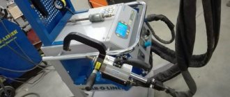
Baluster for welding machine
A conductor is a material with low resistance through which electric current is transmitted. Due to the fact that the conductor resistance is small, the unproductive losses of electricity are insignificant. This is a common practice in constructing electrical circuits. But other problems also happen, just the opposite. That is, the conductor resistance must be increased to the maximum possible value.
The need is most often dictated by inflated current values. Their value must be adjusted to certain requirements, which are less than the nominal ones. For such purposes, the ballast was invented. It speeds up the welding process and makes it easier. A ballast rheostat is a special device designed to regulate the current during welding.
Features and Specifications
The technical documentation of ballasts for welding indicates several important parameters:
- rated operating amperage with a conditional “dip” of voltage at the terminals;
- adjustment ranges;
- minimum difference between electric currents and currents of adjacent sections;
- duration of work under load (cycle time interval).
There is a classification of ballast rheostats; they are distinguished by several main characteristics:
- along the length of the circuit, it is possible to achieve fine adjustment of current parameters with high accuracy;
- the type of materials used, each alloy has an individual resistance (for high-power welders, a metal with a high electrical loss coefficient is chosen, for compact ones - with a low resistance);
- the thickness of the metal elements, the resistance per unit length and the size of the device depend on this.
When choosing welding equipment, it is advisable to take these features into account.
Ballast rheostat - what is it? Principle of operation
Taking into account the purpose and principle of operation, we can briefly say that a ballast rheostat is a simple installation for increasing resistance during welding. It is characterized by the simplicity of the device and is therefore often built into advanced models of welding machines. In addition, the rheostat can be purchased separately at retail.
According to the principle of operation, the device is a certain point of obstacle in the path of movement of electric current from the source to the cable of the welding machine. An obstacle point is nothing more than an area of high resistance connected to an electrical circuit. Visually it looks like a thick spring. It is equipped with a moving contact. Its movement along the spring allows you to change the length of the path through which the electric current passes. Due to this, the resistance in the circuit changes.
It cannot be said that the different device models on the market have any significant differences. They are equipped almost identically, with the exception of some nuances:
What is the role of the ballast rheostat? If it were not there, then the output current would be 250A. If you add a ballast to the electrical circuit, then with its help this indicator can be reduced to 10A. Any value in this corridor can be set depending on the type of welding work, consumables and materials used.
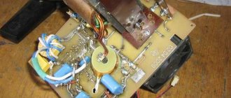
STRUCTURE AND PRINCIPLE OF OPERATION
A ballast rheostat, commonly called a ballast, is a mechanism that increases the resistance of the current and thereby controls its strength. The ballast is easy to use and reliable.
Most often, ballast is present in the design of expensive welding machines. If your device does not have it, you can find it in a special store, but the prices will be quite high.
The design of the device is clear to every welder, so you can easily make it yourself, with your own hands.
A ballast is an element of an electric current circuit where, due to increased resistance, the current strength decreases.
It looks like a spring with many turns of large diameter. It is responsible for resistance called ballast.
The device has a special regulator that allows you to increase or decrease the resistance, and, accordingly, change the current value. This regulator moves along the ballast rheostat, changing its length, that is, the distance that the current travels.
Thus, the resistance changes.
Make a ballast with your own hands
To make a regulator with your own hands, you first need to find a wire of suitable length and thickness. Ideally, it would be made of copper. Additionally, you will need a cylinder - a plastic or pressed cardboard pipe. You definitely need to buy an ammeter, and the moving contact can be made from ordinary wire or other available conductive material.
Now you should make a spring from the wire. To do this, you need to wind it around the cylinder, placing the turns as close as possible in relation to one another. One end is connected to the conductor supplying voltage, and the output will be a moving contact.
After this comes a very important and responsible stage. The workpiece should be checked using an ammeter. It’s good if you have something to make a protective case from. You can, of course, do without it. However, in this case, all safety requirements are violated and there is a fairly high probability of electric shock to the welder. Therefore, when working you need to be extremely careful and attentive. And one more nuance. It should be understood that a home-made ballast rheostat does not work as accurately as a factory-made analogue.
WE MAKE THE BALASTNIK INDEPENDENTLY
The most important element that is needed for this is wire, in our example we took copper, but other metals are also suitable.
You will also need a cylindrical shape (you can use a ready-made small pipe or simply weld a new shape from thick metal), a removable contact (a wire from a welding holder is suitable for this) and an ammeter to measure the current.
The wire must be wound onto a cylindrical shape, placing a turn every centimeter. We connect the wire from the holder to the end of the springs where the current-carrying element will be located.
Then all that remains is to measure the current strength to understand exactly how the rheostat changes it.
Although it is easy to make a ballast rheostat with your own hands, you need to remember that a self-made device may be inferior in accuracy to a factory one. To avoid accidents, you need to work strictly according to safety precautions.
Do-it-yourself devices are not covered by a housing, which is why their fastening may not be very reliable.
Setting up the rheostat
High-quality welding is possible only if the stability of the electric arc is ensured, which is expressed in optimal current-voltage indicators. Modern inverters have proven themselves best in this regard. A good result was achieved thanks to two-level current conversion and the ability to switch modes of the inverter itself.
Other welding machines cannot provide such a result. Therefore, they are equipped with an additional adjustment device - a ballast rheostat. It makes it possible to very accurately regulate the current coming from the transformer, compensate for its strength and ensure the stability of the electric arc. One of its main components is nichrome wire in a parallel connection circuit. Each section of the rheostat is connected to the circuit independently using a switch.
Each rheostat has two operating functions:
The effectiveness of a ballast rheostat is directly proportional to the number of turns of the spring or the number of rheostat sections. The more elements that can be connected to the circuit, the more the output current decreases.
The highlight is that in a series electrical circuit the sections are connected in parallel. Thanks to this solution, high-quality results are ensured. Voltage adjustment in the welding machine is carried out by connecting or, conversely, disconnecting one of the resistance elements.
The buttons used to change settings are displayed on the front surface of the case. It is easy to control the welding operation. Advanced models of welding machines are equipped with built-in fans that cool the rheostat (spring) when working with high current. In devices that do not have forced ventilation, you need to independently control the number of connected sections and their operating time.
One of the most popular ballast rheostats are the RB series models. They have five positions for adjusting current values and are characterized by precision in operation.
How to adjust the current when welding?
This is a fairly common question that has several solutions. There is one of the most popular ways to solve the problem; adjustment occurs through an active ballast connection at the output of the winding (secondary).
On the territory of the Russian Federation, welding for alternating current consists of a frequency of 50 Hz. A 220V network is used as a power source. And all transformers for welding have a primary and secondary winding.
Regulator for welding current
In units used in an industrial area, current regulation is carried out differently. For example, using the moving functions of the windings, as well as magnetic shunting, inductive shunting of various types.
Ballast resistance stores (active) and a rheostat are also used.
This choice of welding current cannot be called a convenient method, due to the complex design, overheating and discomfort when switching.
A more convenient way to regulate the welding current is to wind the secondary (secondary winding) by making taps, which will allow you to change the voltage when switching the number of turns.
But in this case, it will not be possible to control the voltage over a wide range. They also note certain disadvantages when adjusting from the secondary circuit.
Thus, the welding current regulator, at the initial speed, passes through itself a high-frequency current (HFC), which entails a cumbersome design. And standard secondary circuit switches do not require a load of 200 A. But in the primary winding circuit, the indicators are 5 times less.
As a result, an optimal and convenient tool was found in which adjusting the welding current does not seem so confusing - this is a thyristor.
Experts always note its simplicity, ease of use and high reliability.
The strength of the welding current depends on turning off the primary winding for specific periods of time, at each half-cycle of the voltage. At the same time, the average voltage readings will decrease.
The principle of operation of a thyristor
The regulator parts are connected both in parallel and counter to each other. They are gradually opened by current pulses, which are formed by transistors vt2 and vt1. When the device starts, both thyristors are closed, C1 and C2 are capacitors, they will be charged through resistor r7.
At the moment when the voltage of any of the capacitors reaches the avalanche breakdown voltage of the transistor, it opens, and the discharge current of the joint capacitor flows through it.
After the transistor opens, the corresponding thyristor opens and connects the load to the network.
Then the opposite half-cycle of the alternating voltage begins, which implies the closing of the thyristor, then a new cycle of recharging the capacitor follows, this time in the opposite polarity. Then the next transistor opens, but again connects the load to the network.
Welding with direct and alternating current
In the modern world, DC welding is used to a greater extent. This is due to the possibility of reducing the amount of filler material of the electrodes in the weld. But when welding with alternating voltage, you can achieve very high-quality welding results. Welding power sources operating with alternating voltage can be divided into several types:
- Instruments for argon arc welding. Special electrodes are used here that do not melt, making argon welding as comfortable as possible;
- Apparatus for the production of RDS by alternating electric current;
- Equipment for semi-automatic welding.
Alternating welding methods are divided into two types:
- use of non-consumable electrodes;
- piece electrodes.
There are two types of DC welding, reverse and direct polarity. In the second option, the welding current moves from negative to positive, and the heat is concentrated on the workpiece.
And the reverse concentrates attention on the end of the electrode.
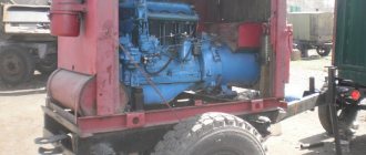
A DC welding generator consists of a motor and a current generator itself.
They are used for manual welding during installation work and in the field.
Manufacturing of the regulator
To make a control device for welding current, you will need the following components:
- Resistors;
- Wire (nichrome);
- Coil;
- design or diagram of the device;
- Switch;
- Spring made of steel;
- Cable.
Operation of the ballast connection
The ballast resistance of the control apparatus is at the level of 0.001 Ohm. It is selected through experiment. Directly to obtain resistance, resistance wires of high power are mainly used; they are used in trolleybuses or on lifts.
Such resistance is turned on permanently or in another way, so that in the future it will be possible to easily adjust the indicators.
One edge of this resistance is connected to the output of the transformer structure, the other is provided with a special clamping tool that can be thrown along the entire length of the spiral, which will allow you to select the desired voltage force.
The main part of resistors using high-power wire is produced in the form of an open spiral. It is mounted on a structure half a meter long. Thus, the spiral is also made from heating element wire.
When resistors made of a magnetic alloy are combined with a spiral or any part made of steel, in the process of passing high current, it will begin to tremble noticeably. The spiral has such dependence only until the moment it stretches.
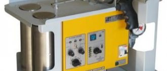
How to make a throttle yourself?
It is quite possible to make your own throttle at home. This occurs when there is a straight coil with a sufficient number of turns of the desired cord. Inside the coil are straight metal plates from the transformer. By choosing the thickness of these plates, it is possible to select the starting reactance.
Let's look at a specific example. A choke with a coil with 400 turns and a cord with a diameter of 1.5 mm is filled with plates with a cross-section of 4.5 square centimeters. The length of the coil and wire should be the same. As a result, the 120 A transformer current will be reduced by half.
Such a choke is made with a resistance that can be changed. To carry out such an operation, it is necessary to measure the deepening of the passage of the core rod into the coil.
Without this tool, the coil will have little resistance, but if the rod is inserted into it, the resistance will increase to its maximum.
A choke that is wound with the correct cord will not overheat, but the core may experience strong vibration. This is taken into account when screeding and fastening iron plates.
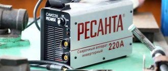
Ballast rheostats series RB
RB-302
A very good model that will accompany any welding transformer to regulate the current during manual or semi-automatic welding using electrodes. Operates in parallel with welding current generators and rectifiers. The model is designed for a range of 27-30V. The maximum current value is 70 amperes, and the minimum is 30A. The device is equipped with air cooling. It is characterized by a good duty cycle of 60%. This means that the maximum permissible duration of switching on (continuous operation) is 10 minutes.
In this model, the current strength is controlled by a 6-stage rheostat. The structural elements are made of high quality materials. The insulation is made of profiled ceramic plates, and a special heat-resistant wire is used to produce the plateau.
RB-302U2
The device is a daughter model of the ballast rheostat discussed above. Designed specifically for use in conditions of high humidity or harsh UV radiation. It can be used to work in open areas, basements and other places with unfavorable conditions.
RB-306
Compared to the RB-302, this device looks preferable. It does not overheat and is much more accurate in adjusting the current strength. The model has an integrated high-performance cooling system. The case has a large number of holes for ventilation, which allows you to make the blowing of the resistors as efficient as possible.
Resistance elements have a modular structure. Thanks to this, diagnosing and changing blocks is much easier. Another big advantage of the installation is the wide range of current adjustment values.
This marking indicates blocks of ballast rheostats, combined from individual elements of RB-306. The systems are designed for use when cutting metal using electric arc welding. This is the optimal solution for controlling current strength when performing operations of this nature.
Ballast rheostats for manual and automatic welding
Current regulators and ballast rheostats are a necessary part of welding equipment.
Their purpose is to create a falling current-voltage characteristic in the electric welding circuit and regulate the strength of the welding current. Existing industrial current regulators do not always meet the requirements of specific production conditions and are constantly being improved. Several innovative proposals are described below. Ballast rheostat RB-700-1 for automatic submerged arc welding. To perform automatic submerged arc welding, multi-station welding rectifiers of the VKSM-1000-1, VDM-1001 types or PSM-1000-4 converters with a rigid external characteristic are used. To ensure regulation of the welding current and obtain a falling external characteristic at a constant source voltage, 3-4 RB-301 ballast rheostats connected in parallel are connected in series with it. The innovators of the welding laboratory of the Soyuzprombummontazh trust manufactured the RB-700-1 rheostat on the basis of the industrial rheostat RB-300-1. Five resistance stages of the new rheostat are made of fechral tape with a cross section of 2X20 mm and a length of 6.2 m. Each stage has a resistance of 0.215 Ohms, and the minimum resistance when all stages are turned on is 0.043 Ohms. Rice. 5. Diagram of the ballast rheostat RB-700-1. With a power source voltage of 60 V and an arc voltage of 30 V, turning on each stage increases the current by 140 A. Thus, by including five resistance stages in series, the following current control stages can be obtained: 140, 280, 420, 560 and 700 A. If necessary, obtain welding currents up to 1000 A and for their finer regulation, the rheostat RB-300-1 is switched on in parallel with the rheostat RB-700-1. Each resistance stage of the RB-700-1 rheostat is a welded metal frame 1 (Fig. 5) with two ceramic tubes 2, on which fechral tape 3 is wound with a slight tightness. The bending of the tape on the insulators during winding is carried out by heating the tape with a gas burner. The individual stages are assembled outside the rheostat housing, then they are connected into a block and installed in the housing. Some resistance leads are attached to the contacts of switches 4, while others are attached to the plate on the bottom side. The ballast rheostat RB-700-1 has high reliability and durability, and is convenient for operation and repair. The use of ballast rheostat RB-700-1 significantly expands the technological capabilities of converters and rectifiers used for manual and automatic welding. During operation, the rheostat RB-700-1 can be used for drying electrodes, fluxes and welding wire. For this purpose, a box of corners with a mesh bottom is mounted above the rheostat cover. The portable ballast rheostat was developed by a team of innovators at the central production repair enterprise Lenenergo. This rheostat is designed to regulate welding current up to 220 A. The ballast rheostat (Fig. 6) has a base 1, a housing 2, a protective casing 3 and a plate switch 5 with a handle 4. Inside the housing 2 there is a resistance made of nichrome wire with a diameter of 5 mm, made in in the form of an accordion of an open ring shape. Rice. 6. Portable ballast rheostat. The ballast rheostat is connected to the welding circuit in series: one end to pin 7, and the other to the pin on switch 5. The welding current is regulated by moving the plate switch to the corresponding accordion link along the entire perimeter of the resistance. To do this, it is enough to tilt the handle 4 up, rotate it to the required angle and bring it into contact with the resistance. The advantages of the described ballast rheostat compared to the known ones are low weight and dimensions, smoother control of the welding current, and ease of manufacture. Repair of ballast rheostats. The innovators of the welding laboratory "Soyuzprombummontazh" when repairing resistance elements of the ballast rheostat type RB-300-1, instead of constantan wire, suggested using wire made of stainless steel 1Х18Н9Т or nichrome. Rice. 7. Diagram of the ballast rheostat RB-300-1. To check the possibility of this replacement, elements 1, 2, 9 and 12 of the ballast rheostat (Fig. 7) were wound with wire made of 1Х18Н9Т steel with a diameter of 2 mm, the remaining elements - with wire made of the same steel with a diameter of 3 mm. Tests showed that the magnitude of the currents in each stage was close to the nominal value for a given rheostat. During prolonged operation of the rheostat, due to heating, the current value drops by 15%, which is caused by the relatively large temperature coefficient of resistance of stainless steel. The length of the wire used was determined by the formula: where l1 and /2 are the length of the new and replaced wires; S1 and s2 - cross-section of the new and replaced wires; po1 and po2 - electrical resistivity of the new and replaced wires. As a result of the implementation of this proposal, the repair of ballast rheostats has been significantly simplified. Author - svarka
mgplm.org
Rules for working with rheostats
The ballast is characterized by simplicity of design and operation. However, certain rules must be followed:
For example, when welding aluminum, the current is adjusted by minor changes that do not exceed 20% of the current value.
Under such conditions, incomplete compensation of the constant component is observed. Full compensation is implied in the case of using devices of the UDGU or UKDN brands, which are additionally equipped with a set of capacitors.
Source
Operating and connection rules
According to GOST RD 03-614-03, it is necessary to regularly check devices in accredited laboratories or service workshops. When connecting a ballast in series to a welding machine, it is important to follow several rules:
- operating conditions must correspond to those stated in the technical documentation, usually indicating a temperature range from -40 to +45ºС and a relative air humidity of no more than 80%;
- there are restrictions on dust and gas contamination, they are associated with the design features of ballast rheostats; the housing has ventilation slots into which electrically conductive dust and vapors can get;
- it is necessary to monitor the heating of the body; when welding aluminum, some types of stainless steel, it is better to connect several rheostats at once or use one in 20% of the range to provide partial compensation instead of full.
The rules apply to self-made ballasts. Electrical safety requirements are becoming more stringent.
Source