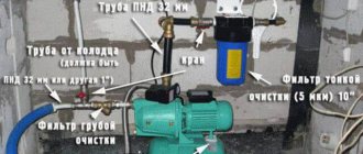
Correct connection of the welding inverter prevents emergency situations and ensures the convenience of performing work operations. The instructions in the accompanying documentation provide a general procedure. To avoid problems, you should carefully study the rules for handling equipment, consider the use of extension cords and autonomous power supplies.
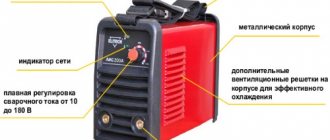
Inverter welding machine.
Welding inverter and its operating principle
To connect metal parts, high heating of the working area is used. The molten parts, after lowering the temperature, form a strong seam with a uniform internal structure. This mount is different:
- durability;
- strength;
- resistance to mechanical and other external influences.
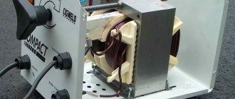
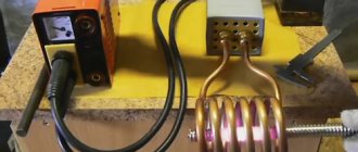
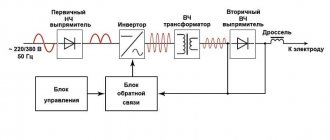
The melt zone (welding pool) is created using an electric arc. An inverter is a device that generates the output signal necessary to ignite it. Equipment in this category is connected to a 220 V or 380 V network. After rectification, the current is converted to alternating current.
Increasing the frequency allows you to reduce the size and weight of the transformer. The final stage is the reverse conversion to high direct current (20-260 A) with a corresponding reduction in voltage.
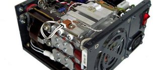
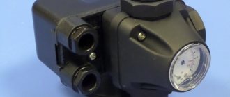
A typical household inverter device is designed to connect to a standard 220V network. The equipment is equipped with:
- digital indicator of operating parameters;
- current regulator;
- LED overheat alarm.
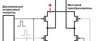
Principle of operation.
The automation unit provides:
- “hot” (quick) start;
- correction of the output signal to prevent sticking of the electrodes.
Connecting cables are supplied as standard. Protective devices and technological accessories along with consumables are purchased separately.
What is the wire for a welding inverter?
Note that the selection of welding wires for the inverter is made solely on the basis of the technical characteristics of both the cable itself and the welding machine. The stability and durability of the inverter depends on this.
If you try to compensate for the loss of voltage and current by adding values on the unit panel, then this measure will most likely damage the inverter electronics. It turns out that it is easier to bring the device closer to the welder’s workplace than to spend a considerable amount on repairing the unit after lengthening the cables.
What kind of lighting do you prefer?
Built-in Chandelier
Equipment check
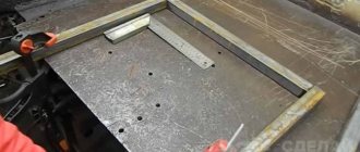
Before connecting the power source, the integrity of the housing and regulator handles is checked by external inspection. Organize the workplace as follows:
- clear a flat area (metal table);
- set a minimum distance of 2 m from the device to the walls;
- connect the protective grounding circuit;
- eliminate explosive (flammable) objects.
Effective ventilation of the room during welding is recommended to prevent harm to health from the polluted atmosphere. You need to prepare a mask, leggings, and electrodes in advance. Free passage of unauthorized people into the work area should be prevented. Remove foreign objects that interfere with individual operations.
We recommend reading How an inverter welding machine works
Preparation for work and connection
Once protective clothing, shoes, a welding mask and electrodes have been prepared, you can proceed to connecting the device. Due to the increased power of the equipment, it is necessary to become familiar with the characteristics and capabilities of the network used as a power source. As a rule, there are no special problems, since all household inverters are designed for 220 volts.
The only requirement related to safety is the installation of a machine with the necessary parameters. This will avoid negative consequences in the event of short circuits and other unforeseen situations. Next, the welding inverter is placed at the workplace in compliance with certain rules and technical standards:
- The minimum distance from walls and large objects is 2 meters.
- Protective grounding is mandatory.
- There should be no flammable or explosive objects or substances nearby.
- For welding work, you should use a metal table or just a free platform.
Having prepared the workplace, you can connect the welding inverter. Each cable and wire is inserted into the desired inverter socket. An electrode is fixed in the holder, and a ground clamp is connected to the metal workpiece. Not only a household network of 220 V can be used as a current source, but also an industrial network of 380 V. In the absence of stationary networks, the use of a gasoline or diesel generator is allowed.
Electrical connection diagram
Welding of thick (16-17 mm) sheets of metal is performed with 6 mm electrodes at a set output current of 240±20A. In this mode, the load on the power supply increases, which is accompanied by a voltage drop. If the corresponding value is less than the permissible operating parameters, the automation will turn off the inverter.
Another problem is limited wiring options. Aluminum (copper) conductors of the household network are designed for 10 (16) A. It is recommended to check the compliance of the power consumption of the device with the operating parameters of the circuit breakers and fuses.
The figure shows a connection diagram for a welding machine, which minimizes the influence of powerful equipment on other equipment:
Welding machine connection diagram.
It is recommended to straighten the network cable. A bent conductor creates inductive reactance, which increases the load on the power supply. The areas that form the coils overheat until the protective shell is destroyed.
Example of connecting a single-phase voltage stabilizer
Connecting a 220 volt stabilizer in the simplest case can be done according to one of the given diagrams, depending on the sequence in which the meter and the input circuit breaker are already connected. In any case, it is necessary to ensure that the stabilizer is grounded. The essence of connecting a stabilizer is that voltage from the network is supplied to the input of the stabilizer, and electricity consumers are connected to its output.
Installation options for voltage stabilizers
The connection diagrams show a version of the terminal block on the rear wall of the voltage stabilizer with five contacts. It happens that the grounding terminal is located separately: the grounding conductor needs to be connected to it. Sometimes there is only one terminal N (zero), then both neutral wires: both the input wire and the one for consumers are connected to it.
Before directly connecting the stabilizer, it is necessary to de-energize the electrical network in the room using an input circuit breaker. Then you should make sure that it is really missing using an indicator or multimeter. The power switch and bypass switch of the device must be turned off.
After completing the electrical installation, power is supplied to the stabilizer, and then it is turned on. The unit's internal timer delays its startup, a click is heard, and power is supplied. The display shows the output voltage value of 220V. Most modern devices may display the following information:
- the L symbol means that the input voltage has dropped below that permissible for operation of the device;
- the symbol H means that the input voltage has risen above what is permissible for operation of the device;
- the CH symbol means that the total power of consumers connected to the device is higher than permissible.
Installing a voltage stabilizer in the basement
Let's consider a practical example of connecting a stabilizer to a single-phase 220 volt network using the example of a relay device RESANTA ASN-10000/1-Ts. The device is installed in the basement, where no one is disturbed by the clicking of the relay and the noise of the built-in vacuum cleaner located nearby. In the wall there is a mounting box with a terminal block and a machine for connecting the stabilizer.
Shelf for installing a voltage stabilizer
The unit is placed on a shelf, which is arranged on pieces of reinforcement hammered into the wall. The gap between the wall and the shelf, as well as the free space under it, ensures air flow through the device body.
At the entrance to the house there is a machine with a nominal value of 40A, which corresponds to a maximum power consumption of about 8 kW. The RESANTA ASN-10000/1-Ts stabilizer is somewhat more powerful, however, to reduce the load on the device, not all consumers are connected through it. The result is the following wiring diagram.
Connecting the RESANTA relay stabilizer
In this case, to protect against leaks, an RCD (residual current device) is installed after the meter. A number of consumers, for example: lighting, sauna heater, instantaneous water heater and some sockets have unstabilized power.
Since the RESANTA stabilizer is located in the basement and far from the entrance to the house, an additional automatic machine and a block for electrical installation are installed in front of it. This allows you to service and repair the device, if necessary, without turning off the unstabilized power in the house.
The installation is carried out with a cable, which consists of five stranded wires. This allows you to move the device freely.
In accordance with the diagram, a 4-pin terminal block is installed in the box, the fifth wire is connected to the machine. It should be clarified that in addition to what is indicated in the diagram, the power cable for the socket of the built-in vacuum cleaner is connected to the terminal block (enters the box from below). On the top right is the cable that supplies power to the stabilizer, as well as the cable connected to the load. In this case:
- green wire – ground;
- blue – zero;
- white (brown) – phase.
Connecting the cable to the block in the distribution box
Other DIY connection methods
In an older home, the protective devices, wiring, and outlets are not designed to withstand heavy loads. High current causes a short circuit. Voltage surges can damage household appliances in your own apartment and those of your neighbors. To eliminate connection problems, you should consider solving this and other typical problems.
Using a current generator
To organize autonomous power supply, a compact power plant with a gasoline (diesel) engine is used. Such a generator can be purchased or rented for the duration of work operations. When choosing equipment, check:
- power;
- voltage stabilization;
- compliance with working conditions.
Calculation of output parameters for the considered example with welding of thick sheets:
- current – 240 A;
- voltage – 40 V;
- power – 9600 W = 240*40.
A 10 kW generator in this mode will operate at the limit of its capabilities. This reduces the life of functional units and increases the risk of overheating and breakdowns. To eliminate negative factors, choose a source with a power reserve of 25±5%.
Using extension cords
The length of the serial network cable does not exceed 4 m. To expand the working area, a “carrying” is used. If the welding current is not more than 150 A, a 20-meter extension cord with a conductor cross-sectional area of 2.5 mm square is suitable. The power line is installed without bends to eliminate the parasitic influence of inductive reactance.
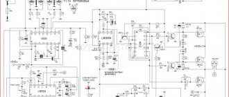
We recommend reading Schematic diagram of the inverter
Selecting cable parameters
To transmit high current, a conductor with a large cross-section in a thick protective sheath is used. Fixed terminals are used to connect to the welding machine. When choosing a cable, pay attention to the following details:
- copper conductor provides low resistivity;
- the use of aluminum reduces the cost of the product;
- the multi-core design maintains the integrity of the core after repeated twisting/straightening cycles;
- The shell with special additives is resistant to high and low temperatures.
Important parameters of cable products are determined by special markings in the name:
- HL (T) – the product is intended for use in cold climates down to -60°C (tropical);
- N – non-combustible insulation;
- KG – flexible cable;
- PES is a modification for a semi-automatic device.
A suitable cross section is selected taking into account the current strength (maximum):
- 6 mm sq. – 100 A;
- 10 – 120;
- 25 – 200;
- 35 – 290;
- 50 – 300.
| Conductor cross-sectional area, mm sq. | |||
| Current (I), A | Cable length, m | ||
| 0-15 | 15-30 | 30-60 | |
| 30-100 | 25 | 25 | 50 |
| 100-200 | 35 | 50 | 70 |
| 200-300 | 50 | 70 | 90 |
For an accurate calculation, use the formula D=S/K, where:
- D – permissible length;
- C – cross-sectional area;
- K – correction factor (K=I/100).
When checking the package, in addition to the cable, you should select the correct holder and clamp for connecting the ground.
When choosing a cable, you need to pay attention to a number of details.
Example of connecting a single-phase voltage stabilizer
Connecting a 220 volt stabilizer in the simplest case can be done according to one of the given diagrams, depending on the sequence in which the meter and the input circuit breaker are already connected. In any case, it is necessary to ensure that the stabilizer is grounded. The essence of connecting a stabilizer is that voltage from the network is supplied to the input of the stabilizer, and electricity consumers are connected to its output.
Installation options for voltage stabilizers
The connection diagrams show a version of the terminal block on the rear wall of the voltage stabilizer with five contacts. It happens that the grounding terminal is located separately: the grounding conductor needs to be connected to it. Sometimes there is only one terminal N (zero), then both neutral wires: both the input wire and the one for consumers are connected to it.
Before directly connecting the stabilizer, it is necessary to de-energize the electrical network in the room using an input circuit breaker. Then you should make sure that it is really missing using an indicator or multimeter. The power switch and bypass switch of the device must be turned off.
After completing the electrical installation, power is supplied to the stabilizer, and then it is turned on. The unit's internal timer delays its startup, a click is heard, and power is supplied. The display shows the output voltage value of 220V. Most modern devices may display the following information:
- the L symbol means that the input voltage has dropped below that permissible for operation of the device;
- the symbol H means that the input voltage has risen above what is permissible for operation of the device;
- the CH symbol means that the total power of consumers connected to the device is higher than permissible.
Installing a voltage stabilizer in the basement
Let's consider a practical example of connecting a stabilizer to a single-phase 220 volt network using the example of a relay device RESANTA ASN-10000/1-Ts. The device is installed in the basement, where no one is disturbed by the clicking of the relay and the noise of the built-in vacuum cleaner located nearby. In the wall there is a mounting box with a terminal block and a machine for connecting the stabilizer.
Shelf for installing a voltage stabilizer
The unit is placed on a shelf, which is arranged on pieces of reinforcement hammered into the wall. The gap between the wall and the shelf, as well as the free space under it, ensures air flow through the device body.
At the entrance to the house there is a machine with a nominal value of 40A, which corresponds to a maximum power consumption of about 8 kW. The RESANTA ASN-10000/1-Ts stabilizer is somewhat more powerful, however, to reduce the load on the device, not all consumers are connected through it. The result is the following wiring diagram.
Connecting the RESANTA relay stabilizer
In this case, to protect against leaks, an RCD (residual current device) is installed after the meter. A number of consumers, for example: lighting, sauna heater, instantaneous water heater and some sockets have unstabilized power.
Since the RESANTA stabilizer is located in the basement and far from the entrance to the house, an additional automatic machine and a block for electrical installation are installed in front of it. This allows you to service and repair the device, if necessary, without turning off the unstabilized power in the house.
The installation is carried out with a cable, which consists of five stranded wires. This allows you to move the device freely.
In accordance with the diagram, a 4-pin terminal block is installed in the box, the fifth wire is connected to the machine. It should be clarified that in addition to what is indicated in the diagram, the power cable for the socket of the built-in vacuum cleaner is connected to the terminal block (enters the box from below). On the top right is the cable that supplies power to the stabilizer, as well as the cable connected to the load. In this case:
- green wire – ground;
- blue – zero;
- white (brown) – phase.
Connecting the cable to the block in the distribution box
Basics of using a welding inverter
At the preparation stage, the features of the technological process are clarified. A 2.5 mm electrode is used at a current of 90±10A for welding workpieces of the following thickness (mm):
- cast iron – 3 or more;
- stainless steel – 1.5;
- “soft” steel grades - from 2 to 5.
To find out how to connect a welding inverter under other initial conditions, use the reference data. Based on the results of the test seam, the operating parameters are adjusted.
As the current increases:
- the seam is deeper;
- you can move the electrode faster without compromising the reliability of the connection.
We recommend reading: How to repair a welding inverter yourself
Before welding, thoroughly clean the surfaces. Remove rust, grease, paint. To create a high-quality seam, both workpieces are heated with equal intensity.
Distribute the melt evenly on the sides. The reduction in electrode length and the corresponding change in arc parameters should be taken into account.
Training improves work skills. For beginners, markings highlight the connection line to improve visibility. The electrode is moved at an angle of 30-60°. Maintain a constant arc length of 2-3 mm.
Connection with different polarity
Electrons move in a conductor from minus to plus. Therefore, the seam parameters depend on how to connect the clamp and ground cables, taking into account polarity.
The direct method is to connect the minus to the electrode. In this case, the heating of the workpiece improves. The technology is used to join thick sheets.
Reverse polarity is used to perform accurate work operations. The comparatively lower temperature effect prevents through-burning of thin products.
Precautionary measures
To safely reproduce technological operations, the following rules apply:
- check the integrity of the device and insulation;
- measure voltage (in idle mode U=0);
- check the compliance of the power supply network with the connected load;
- remove foreign objects from the work area;
- install protective grounding;
- create good ventilation and illumination;
- use shoes with rubber soles (mat, wooden flooring) to prevent electric shock;
- Use protective clothing, gaiters, and a mask.
Before creating a connection, check the voltage sag in the network by test welding at maximum current. It is recommended to place sand or other means to quickly extinguish a fire at a short distance from the work area.
How to connect welding wires to a welding inverter - VET engineer
- Expressive means of language Info lesson metaphor comparison metonymy synecdoche
- Is there an opposition in a democratic regime?
- Presentation on social studies on the topic “The role of the media in political life” (grade 11) Why have historical documentaries become so popular?
- Why does the question of the meaning of life, according to the philosopher, excite and torment a person?
- Family interests almost always ruin public interests
- What kind of coca plant is this?