Do you have a cheap Chinese 1000 watt converter and after actually using it you found out that the power is actually not 1000 but only 300 watts? no problem! The Chinese always lie, this is no longer news. Instead, all Chinese inverters are made with a reserve, that is, they can be “powered up” by two or even three times, how?
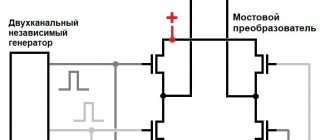
Exclusively in all pulse converters 12-220 there is the same circuit. This is a regular push-pull inverter, there are two master oscillators, the first of which sets the operating frequency of the pulse inverter, and the second sets the frequency of the output transistors to obtain 50 Hz at the output.
How can you increase power? actually quite simple.
In the primary circuit, in the case of inverters up to 600 watts, there are two powerful field switches such as IRF3205 IRFZ44 and their analogues, we either need to replace them with switches with a higher current, or parallel two switches in each arm (see diagram of pulse converters).
The output voltage from the transformer output is rectified by the diode bridge and supplied to the electrolytic capacitor.
The second step is to replace the rectifier diodes with more powerful ones, in my case I replaced UF4007 (1A, 1000V) with UF5408 (3A, 1000V), then we replace the electrolytic capacitor with 400 Volt 10 µF, with 400V 68 µV (we simply increase the capacitance by 3-5 times).
In some cases, the output field switches cost IRF740 or 840, if this is so, then we do not touch the output part, since these keys have a permissible current of 8-10 Amperes, and if the keys have a permissible current of 2-5 Amperes, then we also replace them with more powerful ones .
After this, the rework stage is completed, at the end we do not forget to replace the built-in fuse at the power input (usually on the positive), we just take a fuse that is twice as powerful.
Well, the inverter power is already 2-3 times higher than the initial power. Everything is quite simple and inexpensive.
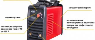
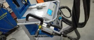
The choice of household welding machines on the modern market is huge - from transformer and inverter machines to plasma cutting machines. The main area of use of this electrical equipment for domestic purposes is the repair of automobiles and motorcycles, welding work on small construction sites (dacha construction). In this article, I propose to consider some points on the modernization of household transformer welding machines using the example of BlueWeld welding model Gamma 4.185.
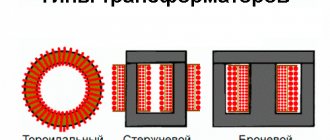
Let's look at the circuit diagram of the device - as you can see, there is nothing complicated - a regular power transformer, with a 220/400V primary winding, with thermal protection and a cooling fan.
The operating current of the device (from 25 to 160A) is regulated by the retractable part of the transformer core. The device is designed to work with coated electrodes from 1.5 to 4 mm in diameter. What was the prerequisite for the modernization of this device? First of all, the instability of the supply voltage in the area where it was planned to use this device - on other days it barely reached 170V (by the way, some inverter devices simply do not start at this supply voltage). In addition, the device was not initially designed for making welds with high aesthetic characteristics (for example, when using electric arc welding in the process of artistic cold forging of metal or when welding thin-walled profile pipes) - in general, the main purpose of the device was to “solder” two iron blanks together. Among other things, it was very difficult to “light” the arc with this welding even at the rated supply voltage - there is no need to talk about reduced voltage at all. As a result, it was decided, first of all, to switch the device to direct current (for the stability of the electric arc and, as a result, to increase the quality of the welded joint) and also to increase the output voltage for more stable and easier ignition of the electrode. For these purposes, the rectifier/multiplier circuit designed by A. Trifonov was ideal - the circuit diagram (a) and current-voltage characteristics (b) are shown in the figure.
A special role in this technical solution of a seemingly ordinary rectifier is played by the X1X3 jumper - by inserting it, a rectifier device is obtained from a conventional diode bridge VD1-VD4 with a low-frequency filter C1C2L1, at the output of which in idle mode we have double the voltage (compared to the operating option device without a jumper). Let's take a closer look at the operation of the circuit. A positive half-wave of voltage is supplied to the semiconductor valve VD1 and, having charged capacitor C1 to the maximum, returns to the beginning of the transformer winding. In the other half-cycle, the charge passes to the capacitor C2, and from it to the valve VD2 and further to the winding. Capacitors C1 and C2 are connected in such a way that the resulting voltage is equal to the total (twice) voltage, which is supplied through the inductor to the electrode holder and thus contributes to stable ignition of the arc. When the X2X3 jumper is closed and there is no welding arc, valves VD3 and VD4 do not participate in the operation of the circuit. The main advantage of the circuit is that when using a conventional bridge circuit, there is a sharp decrease in the rectified voltage with an increase in the load current at the moment of ignition of the arc; it is necessary to install electrolytic capacitors of huge capacity - 15000 microfarads, and all this despite the fact that at the moment the electrode touches the welded surfaces and instantaneous discharge of a large capacitor, a micro-explosion of the plasma occurs with destruction of the electrode coating, and this impairs ignition. Now a little about the design details.
Typical circuit and principle of operation of the inverter
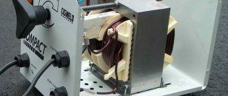
The more expensive the welding inverter, the more auxiliary units in its circuit that are involved in the implementation of special functions. But the power converter circuit itself remains virtually unchanged even with expensive equipment. The stages of transformation of mains electric current into welding current are quite easy to trace - at each of the main nodes of the circuit a certain part of the overall process occurs.
From the network cable, through a protective switch, voltage is supplied to a rectifying diode bridge coupled with high-capacity filters. In the diagram, this area is easy to notice; there are impressive-sized “banks” of electrolytic capacitors located here. The rectifier has one task - to “turn” the negative part of the sine wave symmetrically upward, while the capacitors smooth out the ripples, bringing the direction of the current almost to a pure “constant”.
Scheme of operation of the welding inverter
Next in the diagram is the inverter itself. This part is also easy to identify; the largest aluminum radiator is located here. The inverter is built on several high-frequency field-effect transistors or IGBT transistors. Quite often, several power elements are combined in a common housing. The inverter again converts direct current into alternating current, but at the same time its frequency is significantly higher - about 50 kHz. This chain of transformations allows the use of a high-frequency transformer, which is several times smaller and lighter than a conventional one.
The output rectifier removes the voltage from the step-down transformer, because we want to weld with direct current. Thanks to the output filter, the nature of the current changes from a high-frequency pulsating current to an almost straight line. Naturally, in the considered chain of transformations there are many intermediate links: sensors, control and control circuits, but their consideration goes far beyond the scope of amateur radio electronics.
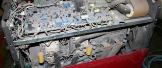
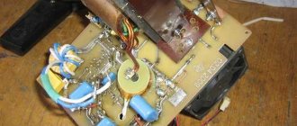
Design of the welding inverter: 1 - filter capacitors; 2 - rectifier (diode assembly); 3 - IGBT transistors; 4 - fan; 5 - step-down transformer; 6 — control board; 7 - radiators; 8 - throttle
Do-it-yourself modification of a welding inverter - Machine tools, welding, metalworking
- Date: 02-06-2015
- 288
- : 48
In recent years, the inverter has become one of the most popular welding machines. It is now used by many professionals and ordinary people. In some cases, such equipment has to be modified.
The modification of the welding transformer can be entrusted to professionals, or you can do it yourself. After all, this is what all the work basically boils down to. In a welding inverter, a transformer plays a very important role, which converts the incoming voltage, increasing its value to the required level.
Modifying a welding inverter with this information will turn into a real pleasure.
Diagram of a welding inverter.
If you take a good look at a welding machine of this type, you will immediately notice its simplicity. The system is a simple voltage converter. The primary winding of a power transformer is quite simple. It is designed for an input voltage of 220/400 Volts.
Of course, there is thermal protection against overheating and a cooling fan. All these parts are an integral part of the inverter. This is where the opportunity for improvement lies. Basically, almost all inverters have a similar circuit.
It is worth noting that they are not designed to work with the highest currents. Most often, the value of this parameter does not exceed 200 Amperes. Upgrading the circuit is not always necessary.
In some situations this is not necessary, but the place of use must have a stable supply voltage.
Prerequisites for modernization
Table of required technical characteristics for a welding inverter.
There are several basic prerequisites that force people to move on to modifying a welding transformer. Firstly, if this unit is used in a place where the voltage is unstable. It is designed for stable consumption from 220 to 400 Volts, but this cannot always be achieved. In some cases, the supply voltage may drop far below a critical level.
For example, if it drops to 170 Volts, then there is a high probability that the transformer will not work, and, accordingly, the inverter. Devices of this type are not intended for artistic welding. They can rather be used for working with large parts. If you need artistic welding, you will also have to move on to modifying the welding transformer.
Such a device, even at rated voltage values, does not always allow ignition of an arc. The output stage of the transformer does not always produce the required high value. If we talk about lower values, then disaster can happen. That is why, if such problems arise, you can safely move on to revision.
All the work in this case comes down to installing a diode bridge to rectify the current, which will produce a more stable arc at the output and will lead to an increase in the output voltage of the transformer so that ignition can be carried out even with insufficient power. These are very useful solutions that each person can implement on their own.
Work process
Functionality of the welding inverter.
All the work boils down to adding a jumper to the circuit, consisting of a rectifier bridge with a low-pass filter.
The result is a rectifier device, the output of which, at idle, is the value of double the voltage. You can consider in more detail the process of operation of the circuit with a jumper.
First, a half-voltage wave enters the first valve, passing through which it enters the filter.
As a result, the rectified voltage is supplied to the transformer winding. The capacitor in the circuit is fully charged. Next, the second half-wave enters the second diode, passing through which it enters the second capacitor. Accordingly, it is also charged to the maximum.
As a result, it turns out that according to the circuit, the voltages from both elements are added together, which leads to a doubling of the value of this parameter at the output. This is exactly what had to be achieved so that the transformer would allow the arc to be ignited without any difficulty. So, we can assume that the first problem is completely solved.
Power supply diagram for an inverter welding machine.
It is also worth noting the fact that the third and fourth rectifiers do not work in any way when there is no load in the circuit, that is, they do not participate in the work process. The modified rectifier bridge circuit allows you to maintain stable output voltage levels, while the standard principle does not allow you to work with maximum arc quality.
This is due to the fact that when the electrode touches the working surface, a sharp discharge of the capacitor occurs, and this leads to a micro-explosion.
In such a situation, you should not count on high-quality welding of surfaces. So, the modified bridge will allow you to get a truly amazing result.
It allows you to work not only with thick metals, but also to perform jewelry work.
A few words about the details themselves
Welding inverter choke circuit.
Now it’s worth talking about what details need to be included in the circuit in order to get a very good result. Nothing supernatural will be used. All parts can be purchased without any problems in specialized stores.
As for rectifier diodes, it is best to use the D161 model with standard cooling radiators that are installed on them.
You can create a mixed circuit in which rectifiers of the previous brand, as well as model B200, will be used.
In this situation, the device turns out to be more compact, since the radiators of each model have different dimensions. It is easier to connect them using a special pin.
Almost any model of these elements can be used as capacitors, but it is better to play it safe and install MBGOs that do not have polarity.
For stable operation of the device, you will have to select the capacity of each element.
To do this, either the random method or mathematics is used. In most cases you can get by with 400 µF.
The current inductor is wound around the transformer core. To do this, a sufficiently large wire must be used. In most cases, you can get by with a cord with a diameter of 10 square millimeters.
You need to wind until the window is full. The result should be a space without any gaps. It is worth laying textolite between the halves of the core. It is used as an insulator.
The result is an inverter with stable arc performance and stable ignition. This is what was worth pursuing.
Increasing efficiency: recommendations
Scheme of operation of a welding inverter.
A welding inverter is a very powerful unit that consumes a huge amount of electricity. Of course, this phenomenon can be combated using various methods. One of them will be offered right now.
The transformer significantly influences the voltage boost in the network. If the work is carried out constantly, then you can be sure that the light in the house will burn dimly. This leads to discomfort for everyone around.
We need to look for the right way out of the situation.
The process of lowering the voltage is extremely simple. We will have to introduce another modification to the welding inverter.
An additional output is made from the secondary winding, that is, the number of its turns is reduced.
Of course, everyone can start arguing, because the quality of combustion will significantly deteriorate, but in fact there is also one trick here that will allow you to maintain a stable arc.
Its capacity should be approximately 15 thousand microfarads. This will be quite enough. Of course, for each specific device this value may vary, but in most cases it varies from 10 to 18 thousand microfarads.
This is what you should focus on.
So, now every reader knows how to modify a welding inverter in order to have an optimal arc at the output, which will allow you to work with even the most demanding and thin materials.
Do-it-yourself repairs and modifications to welding inverters
The characteristics of most budget inverters cannot be called outstanding, but at the same time, few will refuse the pleasure of using equipment with a significant margin of reliability. Meanwhile, there are many ways to improve an inexpensive welding inverter.
Units suitable for modernization
The most important parameter of any welding machine is the current-voltage characteristic (CVC), which ensures stable arc burning at different arc lengths. The correct current-voltage characteristic is created by microprocessor control: the small “brain” of the inverter changes the operating mode of the power switches on the fly and instantly adjusts the parameters of the welding current. Unfortunately, it is impossible to reprogram a budget inverter in any way - the control microcircuits in it are analog, and replacement with digital electronics requires extraordinary knowledge of circuit design.
However, the “skills” of the control circuit are quite enough to level out the “crookedness” of a novice welder who has not yet learned to hold the arc stably. It is much more correct to focus on eliminating some “childhood” diseases, the first of which is severe overheating of electronic components, leading to degradation and destruction of power switches.
The second problem is the use of radioelements of questionable reliability. Eliminating this drawback greatly reduces the likelihood of breakdowns after 2–3 years of operation of the device. Finally, even a novice radio engineer will be quite capable of implementing an indication of the actual welding current to be able to work with special brands of electrodes, as well as carry out a number of other minor improvements.
How to use a homemade device
After connecting a homemade device to the circuit, the controller will automatically set a certain current strength. If the wire voltage is less than 100 Volts, this indicates a malfunction of the device. You will have to disassemble the device and recheck the correct assembly again.
Using this type of welding machine, you can solder not only ferrous, but also non-ferrous metals. In order to assemble a welding machine, you will need not only knowledge of the basics of electrical engineering, but also free time to implement the idea.
Inverter welding is an indispensable thing in any owner’s garage, so if you have not yet acquired such a tool, then you can make it yourself.
The characteristics of most budget inverters cannot be called outstanding, but at the same time, few will refuse the pleasure of using equipment with a significant margin of reliability. Meanwhile, there are many ways to improve an inexpensive welding inverter.
Improved heat dissipation
The first drawback that plagues the vast majority of inexpensive inverter devices is a poor heat removal system from power switches and rectifier diodes. It is better to begin improvements in this direction by increasing the intensity of forced airflow. As a rule, case fans are installed in welding machines, powered by 12 V service circuits. In “compact” models, forced air cooling may be completely absent, which is certainly nonsense for electrical equipment of this class.
It is enough to simply increase the air flow by installing several of these fans in series. The problem is that the “original” cooler will most likely have to be removed. To operate effectively in a sequential assembly, fans must have an identical shape and number of blades, as well as rotation speed. Assembling identical coolers into a “stack” is extremely simple; just tighten them with a pair of long bolts along diametrically opposite corner holes. Also, do not worry about the power of the service power supply; as a rule, it is enough to install 3–4 fans.
If there is not enough space inside the inverter housing to install fans, you can install one high on the outside. Its installation is simpler because it does not require connection to internal circuits; power is removed from the power button terminals. The fan, of course, must be installed opposite the ventilation louvers, some of which can be cut out to reduce aerodynamic drag. The optimal direction of air flow is towards the exhaust from the housing.
The second way to improve heat dissipation is to replace standard aluminum radiators with more efficient ones. A new radiator should be selected with the largest number of fins as thin as possible, that is, with the largest area of contact with air. It is optimal to use computer CPU cooling radiators for these purposes. The process of replacing radiators is quite simple, just follow a few simple rules:
- If the standard radiator is isolated from the flanges of the radio elements with mica or rubber gaskets, they must be preserved when replacing.
- To improve thermal contact, you need to use silicone thermal paste.
- If the radiator needs to be trimmed to fit into the case, the cut fins must be carefully processed with a file to remove all burrs, otherwise dust will accumulate on them abundantly.
- The radiator must be pressed tightly against the microcircuits, so you first need to mark and drill mounting holes on it; you may need to cut a thread in the body of the aluminum base.
Additionally, we note that there is no point in changing the piece heatsinks of separate keys; only the heat sinks of integrated circuits or several high-power transistors installed in a row are replaced.
How to assemble inverter welding: step-by-step description + (Video)
To assemble an inverter welding machine, you must complete the following work steps:
1) Housing . It is recommended to use an old computer system unit as a housing for welding. It is best suited as it has the required number of holes for ventilation. You can use an old 10-liter canister in which you can cut holes and place the cooler. To increase the strength of the structure, it is necessary to place metal corners from the system housing, which are secured using bolted connections.
2) Assembling the power supply. An important element of the power supply is the transformer. It is recommended to use 7x7 or 8x8 ferrite as the base of the transformer. For the primary winding of the transformer, it is necessary to wind the wire across the entire width of the core. This important feature entails improved operation of the device when voltage surges occur. It is imperative to use PEV-2 copper wires as wire, and if there is no busbar, the wires are connected into one bundle. Fiberglass is used to insulate the primary winding. On top, after the layer of fiberglass, it is necessary to wind turns of shielding wires.
Transformer with primary and secondary windings for creating inverter welding
3) Power part . A step-down transformer acts as a power unit. Two types of cores are used as a core for a step-down transformer: Ш20х208 2000 nm. It is important to provide a gap between both elements, which is solved by placing newsprint. The secondary winding of a transformer is characterized by winding turns in several layers. It is necessary to lay three layers of wires on the secondary winding of the transformer, and fluoroplastic gaskets are installed between them. It is important to place a reinforced insulating layer between the windings, which will avoid voltage breakdown on the secondary winding. It is necessary to install a capacitor with a voltage of at least 1000 Volts.
Transformers for the secondary winding from old TVs
To ensure air circulation between the windings, it is necessary to leave an air gap. A current transformer is assembled on a ferrite core, which is connected to the circuit to the positive line. The core must be wrapped with thermal paper, so it is best to use cash register tape as this paper. Rectifier diodes are attached to the aluminum radiator plate. The outputs of these diodes should be connected with bare wires with a cross-section of 4 mm.
3) Inverter block . The main purpose of an inverter system is to convert direct current into high-frequency alternating current. To ensure an increase in frequency, special field-effect transistors are used. After all, it is the transistors that work to open and close at high frequencies.
It is recommended to use more than one powerful transistor, but it is best to implement a circuit based on 2 less powerful ones. This is necessary in order to be able to stabilize the current frequency. The circuit cannot do without capacitors, which are connected in series and make it possible to solve the following problems:
Read also: Metal engraving tool
Aluminum plate inverter
4) Cooling system . Cooling fans should be installed on the case wall, and for this you can use computer coolers. They are necessary to ensure cooling of the working elements. The more fans you use, the better. In particular, it is imperative to install two fans to blow over the secondary transformer. One cooler will blow on the radiator, thereby preventing overheating of the working elements - rectifier diodes. The diodes are mounted on the radiator as follows, as shown in the photo below.
Rectifier bridge on the cooling radiator
It is recommended to use an auxiliary element such as a temperature sensor.
It is recommended to install it on the heating element itself. This sensor will be triggered when the critical heating temperature of the working element is reached. When it is triggered, the power to the inverter device will be turned off.
Powerful fan for cooling the inverter device
During operation, inverter welding heats up very quickly, so the presence of two powerful coolers is a prerequisite. These coolers or fans are located on the device body so that they work to extract air.
Fresh air will enter the system thanks to the holes in the device body. The system unit already has these holes, and if you use any other material, do not forget to provide a flow of fresh air.
5) Soldering the board is a key factor since the entire circuit is based on the board. It is important to install diodes and transistors on the board in opposite directions to each other. The board is mounted directly between the cooling radiators, with the help of which the entire circuit of electrical appliances is connected. The supply circuit is designed for a voltage of 300 V. The additional arrangement of capacitors with a capacity of 0.15 μF makes it possible to dump excess power back into the circuit. At the output of the transformer there are capacitors and snubbers, with the help of which the overvoltages at the output of the secondary winding are suppressed.
6) Setting up and debugging work . After the inverter welding has been assembled, several more procedures will need to be carried out, in particular, setting up the operation of the unit. To do this, connect a voltage of 15 volts to the PWM (pulse width modulator) and power the cooler. Additionally connected to the relay circuit through resistor R11. The relay is included in the circuit in order to avoid voltage surges in the 220 V network. It is imperative to monitor the relay’s activation, and then apply power to the PWM. As a result, a picture should be observed in which rectangular areas in the PWM diagram should disappear.
The device of a homemade inverter with a description of the elements
You can judge whether the circuit is connected correctly if the relay outputs 150 mA during setup. If a weak signal is observed, this indicates that the board connection is incorrect. There may be a breakdown in one of the windings, so to eliminate interference you will need to shorten all power supply wires.
Inverter welding in a computer system case
Checking the device's functionality
After all the assembly and debugging work has been completed, all that remains is to check the functionality of the resulting welding machine. To do this, the device is powered from a 220 V power supply, then high current values are set and the readings are verified using an oscilloscope. In the lower loop, the voltage should be within 500 V, but not more than 550 V. If everything is done correctly with a strict selection of electronics, then the voltage indicator will not exceed 350 V.
So, now you can check the welding in action, for which we use the necessary electrodes and cut the seam until the electrode burns out completely. After this, it is important to monitor the temperature of the transformer. If the transformer simply boils, then the circuit has its shortcomings and it is better not to continue the work process.
After cutting 2-3 seams, the radiators will heat up to a high temperature, so after this it is important to allow them to cool down. To do this, a 2-3 minute pause is enough, as a result of which the temperature will drop to the optimal value.
Checking the welding machine
Welding current indication
Even if a digital current setting indicator is installed on the inverter, it does not show its real value, but a certain service value, scaled for visual display. The deviation from the actual current value can be up to 10%, which is unacceptable when using special brands of electrodes and working with thin parts. You can get the actual value of the welding current by installing an ammeter.
A digital ammeter of the SM3D type will cost around 1 thousand rubles; it can even be neatly built into the inverter housing. The main problem is that measuring such high currents requires a shunt connection. Its cost is in the range of 500–700 rubles for currents of 200–300 A. Please note that the type of shunt must comply with the recommendations of the ammeter manufacturer; as a rule, these are 75 mV inserts with an intrinsic resistance of about 250 μOhm for a measurement limit of 300 A.
Literature
- https://www.ti.com/product/ucc28070;
- https://www.ti.com/product/ucc27322;
- https://www.ti.com/tool/tmdshvpsfbkit;
- https://www.ti.com/tool/tmdshvresllckit.
Obtaining technical information, ordering samples, ordering and delivery.
Increasing duty cycle
The on-time duration in the context of welding inverters is more reasonably called the load duration. This is the part of the ten-minute interval in which the inverter directly performs work; the remaining time it must idle and cool.
For most inexpensive inverters, the actual PV is 40–45% at 20 °C. Replacing radiators and an intensive airflow device can increase this figure to 50–60%, but this is far from the ceiling. A PN of about 70–75% can be achieved by replacing some radioelements:
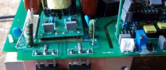
- The capacitors around the inverter keys must be replaced with elements of the same capacity and type, but designed for a higher voltage (600–700 V);
- Diodes and resistors from the key harness should be replaced with elements with higher power dissipation.
- Rectifier diodes (valves), as well as MOSFETs or IGBT transistors, can be replaced with similar, but more reliable ones.
It is worth talking about replacing the power switches themselves separately. First, you should rewrite the markings on the element body and find a detailed datasheet for a specific element. According to the passport data, choosing an element to replace is quite simple; the key parameters are the limits of the frequency range, operating voltage, the presence of a built-in diode, type of housing and current limit at 100 °C. It is better to calculate the latter yourself (for the high-voltage side, taking into account losses on the transformer) and purchase radioelements with a maximum current reserve of about 20%. Of the manufacturers of this type of electronics, International Rectifier (IR) or STMicroelectronics are considered the most reliable. Despite the rather high price, it is highly recommended to purchase parts from these brands.
Choice of electrolytes from Hitachi, Samwha, Yageo
On the electronics market today you can find a large number of suitable capacitors from well-known and little-known manufacturers. When choosing equipment, one should not forget that with similar parameters, capacitors differ greatly in quality and reliability. The most well-proven products are from such world-famous manufacturers of high-quality aluminum capacitors as Hitachi, Samwha and Yageo. Companies are actively developing new technologies for the production of capacitors, so their products have better characteristics compared to competitors' products.
Aluminum electrolytic capacitors are available in several form factors:
- for mounting on a printed circuit board;
- with reinforced snap-in pins (Snap-In);
- with bolted terminals (Screw Terminal).
Tables 1, 2 and 3 present the series of the above manufacturers that are most optimal for use in the pre-rectification unit, and their appearance is shown in Figures 2, 3 and 4, respectively. The given series have a maximum service life (within the family of a particular manufacturer) and an extended temperature range.
Table 1. Electrolytic capacitors manufactured by Yageo
| Name | Capacity, µF | Voltage, V | Ripple current, A | Dimensions, mm | Form factor | Service life, h/°C |
| LV | 470, 560, 680 | 400, 450 | 1,70; 1,90; 2,10 | 35×40, 35×45, 35×50 | Snap-In | 3000/105 |
| L.C. | 470 | 400, 450 | 1,90; 2,10 | 35×45, 35×50 | Snap-In | 5000/105 |
| N.H. | 470…22000 | 400, 450, 500 | 2,4…39,4 | 51×80…89×270 | Screw Terminal | 5000/105 |
Table 2. Electrolytic capacitors manufactured by Samwha
| Name | Capacity, µF | Voltage, V | Ripple current, A | Dimensions, mm | Form factor | Service life, h/°C |
| HY | 470, 560 | 400, 450 | 1,91; 2,14 | 35×45; 35×50 | Snap-In | 7000/105 |
| JY | 470 | 400, 450 | 1,88 | 35×45 | Snap-In | 10000/105 |
| EY | 1500…10000 | 400, 450 | 6,1…24,3 | 51×110…89×160 | Screw Terminal | 7000/105 |
Table 3. Electrolytic capacitors manufactured by Hitachi
| Name | Capacity, µF | Voltage, V | Ripple current, A | Dimensions, mm | Form factor | Service life, h/°C |
| HP3 | 470…2100 | 400, 420, 450, 500 | 2,75…9,58 | 30×40, 35×35…40×110 | Snap-In | 6000/85 |
| HU3 | 470…1500 | 400, 420, 450, 500 | 2,17…4,32 | 35×45, 40×41…40×101 | Snap-In | 6000/105 |
| HL2 | 470…1000 | 400, 420, 450, 500 | 1,92…3,48 | 35×40, 30×50…35×80 | Snap-In | 12000/105 |
| GXA | 1000…12000 | 400, 450 | 4,5…29,7 | 51×75…90×236 | Screw Terminal | 12000/105 |
| GXR | 2700…11000 | 400, 450 | 8,3…34,2 | 64×100…90×178 | Screw Terminal | 12000/105 |
As can be seen from Tables 1, 2 and 3, the product range is quite wide, and the user has the opportunity to assemble a capacitor bank, the parameters of which will fully meet the requirements of the future welding inverter. The most reliable are Hitachi capacitors with a guaranteed service life of up to 12,000 hours, while competitors have this parameter up to 10,000 hours in Samwha JY series capacitors and up to 5,000 hours in Yageo LC, NF, NH series capacitors. True, this parameter does not indicate a guaranteed failure of the capacitor after the specified line. Here we mean only the time of use at maximum load and temperature. When used in a smaller temperature range, the service life will increase accordingly. After the specified period, it is also possible to reduce the capacity by 10% and increase losses by 10...13% when operating at maximum temperature.
Rice. 2. Yageo electrolytic capacitors
Rice. 3. Samwha electrolytic capacitors
Rice. 4. Hitachi electrolytic capacitors
It is noteworthy that in each series you can find a different configuration of capacitor leads - with reinforced snap-in terminals or bolted terminals. Bolted terminals provide guaranteed reliability of the assembly, and capacitors with latched terminals add to the reliability and ease of installation on a printed circuit board.
The considered high-quality aluminum electrolytic capacitors manufactured by Hitachi, Samwha and Yageo can solve almost any problem in the development of a high-frequency inverter welding machine. A distinctive feature of the presented capacitors is that they are developed in accordance with the requirements of RoHS (Directive on the Restriction of the Use of Certain Hazardous Substances in Electrical and Electronic Equipment) and other environmental standards. For advice on application, as well as on the purchase of capacitors produced by all three companies, you can contact their distributor - the COMPEL company.
Winding the output choke
One of the simplest and at the same time most useful additions to a welding inverter will be the winding of an inductive coil that smoothes out the DC ripples that inevitably remain when the pulse transformer is operating. The main specificity of this idea is that the choke is made individually for each individual device, and can also be adjusted over time as electronic components degrade or when the power threshold changes.
To make a choke you will need nothing at all: an insulated copper conductor with a cross-section of up to 20 mm 2 and a core, preferably made of ferrite. Either a ferrite ring or an armored transformer core is optimally suited as a magnetic core. If the magnetic core is made of sheet steel, it needs to be drilled in two places with an indentation of about 20–25 mm and tightened with rivets in order to be able to cut the gap without any problems.
The choke begins to work starting from one full turn, but the real result is visible starting from 4–5 turns. During testing, turns should be added until the arc begins to stretch noticeably strongly, preventing separation. When it becomes difficult to cook with separation, you need to remove one turn from the coil and connect a 24 V incandescent lamp in parallel with the choke.
Fine-tuning the throttle is done using a plumber's screw clamp, which can be used to reduce the gap in the core, or a wooden wedge, which can be used to increase this gap. It is necessary to ensure that the lamp burns as bright as possible when igniting the arc. It is recommended to manufacture several chokes to operate in ranges up to 100 A, from 100 to 200 A and more than 200 A.
What is required for production
In order to make a choke for a semi-automatic machine with your own hands, first of all you should make the required calculations, and then prepare the necessary materials and tools. During the work you will need:
- soldering iron (from 100 W) with accessories;
- bench vice;
- pliers, pliers, hammer, etc.;
- coil core and body;
- getinax (or similar) for gaps;
- varnished cloth;
- keeper tape;
- epoxy or glue;
- copper or aluminum wire (or bar);
- two screw terminals.
In addition, you need a block to secure the reel body, as well as pieces of any plastic or wood to wedge it.
High Speed MOSFET Drivers
The UCC27321/2 are high-speed drivers delivering up to 9 A peak current. These drivers are designed to drive high-power MOSFETs that require high currents to recharge the Miller capacitance during fast switching. They serve as an interface between low-power microcontrollers and high-power MOSFETs. With a load CL = 10 nF, the drivers provide edges of 20 ns, while the delay time of the control signal is 25 ns for a falling edge and 35 ns for a rising edge. The use of drivers reduces the footprint of the control board by simplifying the design and using a single chip instead of multiple discrete components. The UCC27321/2 implements two types of control logic: with inverting (UCC27321) and without inverting (UCC273212) the control signal.
The operating voltage range of the drivers is 4…15 V. To ensure effective control at low supply voltages, the driver uses a hybrid output stage (TrueDrive), using parallel connection of a MOSFET and a bipolar transistor. This architecture allows the driver to be used in most standard industrial applications requiring gate currents of 6, 9, and 12 A. The driver's built-in parasitic diode provides low surge impedance and eliminates the need for an external Schottky limiting diode in many applications.
For flexibility in driver control, the chip provides an additional resolution pin (ENBL). By default it is connected to the supply voltage and can be left unconnected for standard use.
Drivers are available in several packages - SOIC-8, PDIP-8, MSOP-8 PowerPAD. The PowerPad housing has significantly lower thermal resistance, which allows the driver to be used at higher temperatures and improves long-term reliability.
•••