The discovery of the principle of electromagnetic induction by the great scientist Faraday back in 1831 allowed us to take a fresh look at many laws of electrical engineering. It was based on the interaction of electromagnetic fields that 45 years after this, the great Russian scientist P. N. Yablochkov received a patent for the invention of a transformer. The classic definition is as follows: a transformer is an electrical device that converts the current of the primary winding of one voltage into the current of the secondary winding with a different voltage.
The induction effect is formed when the electromagnetic field changes, so for the transformer to operate, an alternating current voltage must be present. Transformation (transmission) is carried out by converting the electrical energy of the primary winding into a magnetic field, and then, in the secondary winding, the reverse conversion of the magnetic field into electrical energy occurs. If the number of turns of the secondary winding exceeds the number of turns of the primary winding, the device will be called a step-up transformer. When connecting the windings in reverse order, a step-down device is obtained.
Design and principle of operation
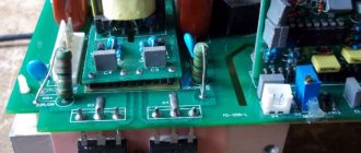
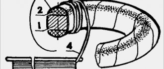
The appearance of a typical current transformer is shown in Figure 1. A characteristic feature of these models is the presence of a dielectric housing. Case shapes can be different - from rectangular to cylindrical. Some designs do not have pass-through bars in the center of the body. Instead, a hole was made to wrap around the wire, which serves as the primary winding.
Step-down transformers
For certain devices used in everyday life, a voltage of 220V is unnecessary - it is recommended to use step-down transformers to connect them (220 to 15 volts or 220 to 10 volts).
The advantages of using these mini-transformers for the home include:
- protection against electric shock and fire (especially important in bathhouses, bathrooms and other rooms with high humidity);
- saving energy consumption (low-voltage lighting devices consume several times less energy than conventional ones);
- extending the service life of devices.
Chargers for phones, laptops and other gadgets already have built-in transformers, but when installing low-voltage lighting using LED and halogen lamps, you need to independently install devices to reduce the voltage.
Read also: Emptiness, apathy after parting
So, buying a transformer for a private home or cottage will not be difficult if you carefully study the types and purposes of various types of devices. The right choice will help ensure the availability of the power required to operate the devices without the risk of equipment failure.
Interesting video: How does a transformer work?
Having examined the features and operating principles of step-up transformers, one can evaluate their importance in power lines. The use of such equipment improves the quality of electricity in household and industrial networks. It is installed everywhere. The presented types of installations are in high demand today.
A step-up transformer is an ordinary transformer (see the purpose and principle of operation of a transformer) that increases the voltage value of an electric current. On the primary winding it is lower, and on the secondary winding it is higher. Thus, the voltage at the output of the device is higher and, due to a certain number of turns of the winding and cross-section, has the desired value.
The principle of operation of a step-up transformer is the value of K (transformation ratio).
When K>1 the transformer is a step-down transformer, and when K is a step-up transformer circuit
How to connect
Connecting transformers in parallel operation is allowed only if all the listed conditions are met. It is possible to operate devices with different groups of windings:
- in groups with a difference of 4 hours (120 degrees), a circular rearrangement of the windings is performed;
- groups with a difference of 6 hours (180 degrees), for example 0, 4, 8 and 6, 10, 2, are connected after changing the places of the beginning and end of the winding of one of the transformers;
- in odd groups, two phases on the high and low voltage windings are swapped.
In all cases, the windings are re-phased.
All installation and switching work is carried out in the absence of high voltage.
How to reduce the output voltage of a transformer?
- Because most transformers are always a center tap for dual power supplies. ...
- Primary transformer 230/110 VAC to secondary transformer 9-0-9 V, 1 A. ...
- Usually we can easily apply it as 18V 1A output without using CT terminal.
- Moreover, we can use it as 9V 2A since both coils are connected in parallel.
Useful tips Connection diagrams Principles of operation of devices Main concepts Meters from Energomer Precautions Incandescent lamps Video instructions for the master Testing with a multimeter
Varieties
The category of boosting types of equipment includes a number of devices that differ in design, purpose, and technical characteristics:
- Autotransformer. It has one combined winding.
- Power. The most common type among devices that increase voltage.
- Anti-resonant. Has a closed design. Due to their special operating principle, they have compact dimensions.
- Grounded. The windings are connected in a star or zigzag pattern.
- Peak transformers. Separate direct and alternating current.
- Household. The improvement in the characteristics of electricity during the operation of a transformer is carried out in a small range. They help eliminate interference in the household network, protect equipment from surges, low and high electricity.
The presented designs differ in power and technical characteristics.
Device types
Depending on the power, design and scope of their application, there are the following types of transformers:
- The autotransformer is structurally designed as one winding with two end terminals, and at intermediate points of the device there are several terminals in which the primary and secondary coils are located.
- The current transformer includes a primary and secondary winding, a core made of magnetic material, as well as optical sensors and special resistors that allow for faster voltage regulation methods.
- A power transformer is a device that transmits current, using the induction of an electromagnetic field, between two circuits. Such transformers can be step-up or step-down, dry or oil-based.
- Anti-resonance transformers can be either single-phase or three-phase. The operating principle of such a device is not much different from power type transformers. Structurally, it is a cast-type device with good thermal protection and a semi-closed structure. Anti-resonance transformers are used when transmitting signals over long distances and under heavy load conditions. Ideal for working in any climatic conditions.
- Grounded transformers (pre-load) . A special feature of this type is the arrangement of the windings in the shape of a star or zigzag. Grounded devices are often used to connect an electric energy meter.
- Peak - transformers are used in radio communication devices and computer production technologies, on the principle of separating direct and alternating current. The design of such a transformer is simplified: a winding with a certain number of turns is located around a core made of ferromagnetic material.
- A home isolation transformer is used when transferring AC power to another device or equipment, thereby blocking the ability of the power source. In domestic conditions, such devices provide voltage regulation and galvanic isolation. Most often used to suppress electrical noise in sensitive devices and protect against the harmful effects of electric current.
Where did he come from
At the beginning of the 19th century, scientists studied the properties of the magnetic field. And it was experimentally shown that an alternating magnetic field is capable of creating a current: it was recorded by instruments on a conductor. However, for a long time no one measured its value.
By the middle of the same century, the properties of ferromagnets and the parameters of the magnetic field were studied, and even a prototype of a transformer appeared - the Ruhmkorff coil. Finally, in 1876, the Russian scientist P. N. Yablochkov patented the world's first rod transformer.
A little later, the first transformers with a closed core began to be produced in England, which became the prototype of almost all modern devices of this type. All further work was carried out in the direction of improvement, and they were based on studying the operational properties of this device. Thus, cores made of laminated material and oil cooling were introduced. In the USSR, the spread of transformers went along with the electrification of the entire country, from the late 20s of the last century.
Bell transformer - parameters and application
Bell transformers have one purpose - to reduce the network voltage to a level suitable for a home or a specific device. This is so that the bell can be placed outside, such as on a fence, where high humidity or the possibility of splashing increases the risk of electric shock. At low voltages this is not dangerous.
The parameters of bell transformers do not change much, but the choice is often severely limited by technical problems.
- Output voltage and output current . Their level is determined by checking the call requirements. Bell transformers with voltages greater than 8 V are relatively rarely used these days. 12 V is the level needed for large, complex doorbells or intercoms. In both cases, this is an absolutely safe voltage. Many bell-type transformers have multiple terminals, combinations of which produce different output voltages (for example, 4, 8, or 12 V);
- Installation method . Many older electrical installations still have a few or dozens of transformers installed. Technically they are usually effective, although efficiency, safety and aesthetics leave much to be desired. These transformers were installed directly on the wall, but today this solution is practically not used. Currently, developers prefer to install transformers for the T-35 bus. A transformer on a DIN rail can be installed without additional holes in the structure and is more versatile;
- Safety . In this regard, the differences are small, since overheating and overload protection are standard, but in each case it is worth paying attention to the offer of individual manufacturers.
Advantages and disadvantages of cores
- Stacked ones are more often used for constructing magnetic cores with an arbitrary cross-section, limited only by the width of the plates. Voltage transformation devices with a square cross-section have the best parameters. The disadvantage of this type of core is the need to tightly tighten the plates, the low fill factor of the coil space, as well as increased dissipation of the magnetic field of the device.
- Twisted cores are much easier to assemble than type-type ones. The entire W-type core consists of four parts, while the U-shaped type has only two parts in its design. The technical characteristics of such a transformer are much better than those of a type-setting transformer. The disadvantages include the need for a minimum gap between parts. With physical impact, the plates of the parts can peel off, and in the future it is very difficult to achieve a tight fit.
- Toroidal cores have the shape of a ring, which is made of transformer iron tape. Such cores have the best technical characteristics and almost complete elimination of magnetic field dissipation. The disadvantage is the difficulty of winding, especially wires with a large cross-section.
In W-type transformers, all windings are usually made on the central rod. In a U-shaped device, the secondary winding can be wound on one rod, and the primary winding on another. Especially often, there are design solutions when windings divided in half are wound on both rods, and then connected to each other in series. At the same time, the wire consumption for the transformer is significantly reduced and the technical characteristics of the device are improved.
Design and principle of operation
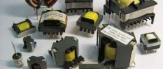
Structurally, the boosting voltage transformation device consists of a core and two windings . The core is assembled from electrical sheet steel plates. The primary and secondary windings are wound on it, made of copper wire of various diameters. The thickness of the transformer winding wire directly depends on its output power.
The core of the device can be rod or armor. When using the product in low-frequency voltage networks, rod magnet wires are most often used, which can be shaped like:
- U-shaped.
- W-shaped.
- Toroidal.
Cores are made from transformer special iron, on the quality characteristics of which many general parameters of the device depend. A core is made of thin iron plates, which are insulated from each other with varnish or a layer of oxide, to reduce losses due to eddy currents. Ready-made halves, which are made from solid iron strips, can also be used.
Manufacturing workflow of coil frames
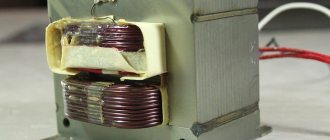
Transformer coil.
When using a round core, it is first wrapped with tape insulation and then the wire begins to be wound directly onto it, distributing the required number of turns throughout the entire ring.
After the winding of the primary winding is completed, it is covered with 3-4 layers of varnished cloth and then the turns of its secondary part begin to be wound on top. When using conventional magnetic cores, the coil frame is made as follows:
- a sleeve pattern is made with cuffs on the sides of the ends;
- cheeks are cut out of cardboard;
- roll the coil body along the marked lines into a small box and seal it;
- put the upper parts (cheeks) on the sleeve and, bending the flaps, glue it.
After this, the wire is covered with tape insulation, having previously brought the ends of the windings out.
How to reduce voltage without a transformer?
Without a transformer, you can step down the voltage using a resistive voltage divider (the load can be part of one of the resistors), rectify the voltage to DC and use a regulator, or both. The voltage can ONLY be increased when converted to DC using a voltage multiplier.
All you need to do is connect the primary to the mains plug as usual, then run another wire from the hot side of the primary and connect it to the neutral secondary terminal. The load (your design) is connected to the neutral side of the primary and to the hot secondary terminal of your transformer.
Expert opinion
It-Technology, Electrical power and electronics specialist
Ask questions to the “Specialist for modernization of energy generation systems”
Re: Increasing the power of the amplifier without rewinding the transformer When the load increases, the current increases at the same voltage; with a further increase in the load, the current will increase accordingly at the same voltage. Ask, I'm in touch!
Other types
In accordance with the performance characteristics, the presented equipment differs in several ways. Depending on the number of circuits, there are single-phase (domestic) and three-phase (industrial) designs.
Various substances are used as a cooling system. There are oil and dry varieties. In the first case, the equipment costs less. Oil is a flammable substance. When used, high-quality protection against accidents is provided. Dry units are filled with a non-flammable substance. They are more expensive, but the requirements for their installation are fair.
Coolant circulation in the system can be forced or natural. There are designs that combine these methods. The variety of types allows everyone to choose the optimal type of device.
Types of power transformers
Power transformers can be divided into several types based on the following characteristics and indicators:
- Cooling type. There are dry and oil transformers. The first option is air-cooled and is used where environmental and fire safety requirements are increased. The second option is a housing filled with oil with dielectric properties, into which a core with windings is immersed;
- Climatic design: external and internal options;
- Number of phases. There are three-phase (the most common) and single-phase;
- Number of windings. There are two-winding and multi-winding options;
- Purpose: increasing and decreasing.
An additional criterion is the presence or absence of an output voltage regulator.
Technological connection to electrical networks
- Required power calculator - an approximate calculation of the need for electrical power to submit an application for technological connection;
- Cost calculator - approximate calculation of the cost of technological connection to electrical networks, depending on the type of connection (existing or new);
- Connection stages - a detailed description of the main stages required for technological connection to electrical networks;
- Answers of JSC Lenenergo to frequently asked questions on the technological connection of additional capacity or new capacity and the conclusion of an energy supply agreement.
Operating principle of a step-up transformer
A step-up transformer works on the same principle as a regular transformer. Step-up transformers draw lower voltage and provide higher voltage. Their work is based on Faraday's laws and rotation coefficient theory.
Inside a step-up transformer, current flows due to the input voltage. The flow of current induces a magnetic flux around the windings, and this flux passes through the core of the transformer.
The voltage in the secondary windings is induced by the secondary winding.
The next operating principle is the rotation coefficient. The gear ratio is expressed as the ratio of the number of turns of the primary winding to the turns ratio of the secondary winding. It is also described as the ratio of input voltage to output voltage.
Turnover ratio = Nprimary/Nsecondary =Vprimary/Vsecondary ———————- (i)
Or, Vsecondary = Vprimary * (Nsecondary / Nprimary) ——————— (ii)
Here Nprimary = number of turns of the primary winding.
Nsecondary = Number of turns of the secondary winding
Vprimary = primary side voltage
Vsecondary = Secondary side voltage
Using the marked equation (ii), we attempt to calculate the secondary stress. It is clear that the input voltage is constant. Now by changing the transformation ratio we can get the desired output voltage. A step-up transformer is used to create a higher voltage output. This is why the ratio (Nsecondary / Nprimary) is set to greater than 1.
Now from the equations we can notice that the secondary N will be larger as opposed to the step down transformer. Therefore, a step-up transformer has a larger number of turns in its secondary windings.
Learn how a transformer works. Click here for navigation!
Parameter calculations
On a simple transformer the primary winding has 440 turns for 220 volts. It turns out 1 volt for every two turns. Formula for counting turns by voltage:
It will be interesting➡ Tesla coil (Transformer) self-assembly on your own
N = 40-60 / S, where S is the cross-sectional area of the core in cm2. The constant 40-60 depends on the quality of the core metal. Let's make a calculation for installing the windings on the magnetic circuit. In our case, the transformer has a window 53 mm in height and 19 mm in width. The frame will be textolite. Two cheeks at the bottom and top 53 - 1.5 x 2 = 50 mm, frame 19 - 1.5 = 17.5 mm, window size 50 x 17.5 mm.
- The winding of a simple high voltage transformer is 2.18 x 450 = 981 turns.
- Low voltage for filament 2.18 x 5 = 11 turns.
- Low voltage filament 2.18 x 6.3 = 14 turns.
We calculate the required diameter of the wires. The power of the transformer core with your own hands is 170 watts in size. On the network winding the current is 170 / 220 = 0.78 amperes. Current density is 2 amperes per mm2, standard wire diameter according to the table is 0.72 mm. The factory winding is made of 0.5 wire, the factory saved money on this.
The assembled magnetic core, together with the components and connecting elements, forms the core of the transformer. The part on which the windings are wound is the rod. The area of the system intended to complete the circuit and not carrying any turns of the circuit is called the yoke. The arrangement of the rods in space serves to divide the system into the following types.
Types of arrangement of rods.
Read also: Why are there more graters than graters?
Number of turns of the primary winding
We take a wire of 0.35 mm, 50 / 0.39 x 0.9 = 115 turns per layer. Number of layers 981 / 115 = 8.5. It is not recommended to draw conclusions from the middle of the layer to ensure reliability. Let's calculate the height of the frame with windings.
Primary of eight layers with 0.74 mm wire, 0.1 mm insulation: 8 x (0.74 + 0.1) = 6.7 mm. It is better to shield the high-voltage winding from other windings to prevent high-frequency interference. In order to wind the transformer, we make a screen winding from one layer of 0.28 mm wire with two layers of insulation on each side: 0.1 x 2 + 0.28 = 0.1 x 2 = 0.32 mm.
The process of winding a transformer coil.
The primary winding will take up space: 0.1 x 2 + 6.7 + 0.32 = 7.22 mm. Step-up winding of 17 layers, thickness 0.39, insulation 0.1 mm: 17 x (0.39 + 0.1) = 6.8 mm. On top of the winding we make layers of insulation 0.1 mm. It turns out: 6.8 + 2 x 0.1 = 7 mm. Height of the windings together: 7.22 + 7 = 14.22 mm. 3 mm left for filament windings.
You can calculate the internal resistance of the windings. To do this, the length of the turn is calculated, the length of the wire in the winding is taken, the resistance is determined, knowing the resistivity from the table for copper.
Read also: Why do you need rosin when soldering?
When calculating the resistance of the primary winding section, a difference of about 6 ohms is obtained. This resistance will give a voltage drop of 0.84 volts at a nominal current of 140 milliamps. To compensate for this voltage drop, we add two turns. Now during loading the sections are equal in voltage.
Maintenance and repair
Step-up transformers are technically complex devices, so self-correction of breakdowns is highly discouraged .
The only thing that can be done with your own hands is rewinding the windings of the device .
Let us take as an example the type that uses multiple windings. This unit contains a magnetic core, which is common to all three inductors. As a rule, one coil is a step-down coil and the other a step-up coil in this device.
It would be a good idea to learn the procedure for checking transformers, which will help you avoid potential problems in the future. Let's look at the whole procedure step by step :
- First you need to inspect the entire block. As a rule, overheating of the system provokes the appearance of some bulges or irregularities, which indicate deformation of some parts.
- We determine the input and output of the device. The first circuit must be connected to the first coil of the device, where the magnetic field itself is formed. The second part, which acts as a receiver of energy from the magnetic field, must be connected to the secondary winding.
- Then you need to determine the filtering of the output signal. It is noteworthy that it is identical for the diodes and capacitors on the second coil of the device.
- Next, you need to remove some parts of the case so that you have full access to the device’s microcircuits. This is necessary so that voltage readings can be determined using a multimeter.
- If the obtained indicators are significantly less than expected (less than 80% of optimal), then the probable cause of the breakdown lies in the entire circuit that connects around the primary winding. To correct the causes, you should disconnect the first coil from the electricity supply to it.
- Next you need to check the secondary output. If there is no filtering, then you need to use power from a multimeter. If you notice that the optimal voltage is not achieved, then the reason may be in the transformer itself, or in the output terminals.
In general, it is better to entrust all these manipulations to the appropriate specialist , who will not only correctly disassemble and assemble the device, but also check the voltage frequency indicators in individual sections of the primary and secondary winding circuits.
Types of products
Now we will describe some of these converters and the features of their design.
Power converter
This is a device that operates in networks and serves to increase or decrease voltage during power transmission. In large power systems, the voltage generated by the power plant is first increased to several hundred volts (or even megavolts) to reduce transmission losses. Then step-down transformers are installed in the regions, and thus the electricity reaches your apartment in several steps. The last transformer in front of your house steps down the voltage from 10 kV to 220 V.
Since our transmission lines are three-phase, with a shift of 120 degrees, there are three coils in your yard booth, and the voltage between the secondary windings of any two of them is 400 (in fact, with the loads turned on - 380) volts. And between any of the phases and the neutral - 220. That’s why on the door of the substation it says “10 kV/400 V/220 V”. Such products are produced in rod and armor types.
Also, a step-down transformer is found in a number of household appliances, where 220 V is converted to 12.
Instrument transformers
They can be found in large substations and power supply plants. They are used to measure the parameters of high-voltage networks, since it is simply impossible to connect measuring equipment at high voltage. Fundamentally, they do not differ from power ones, it’s all about the operating mode and connection diagram.
For measurement accuracy, such transformers are connected to the network in such a way that they have the least possible impact on the measured indicators.
Since these devices are designed to measure relevant parameters, they are subject to certain accuracy class requirements. The measurements take place on a scale, and if the deviations in the secondary winding are small, then in the primary they will be many times higher - that is, they need to be multiplied by the transformation ratio. Therefore, such transformers are subject to regular inspections.
Pulse options
Designed to convert voltage and current that have a pulsed (not sinusoidal) change graph. The task of such an element in the circuit is to transmit a pulse without distorting its shape, which is quite difficult if you remember about parasitic inductances and capacitances, as well as the properties of the core. Therefore, when calculating such transformers, special attention is paid to the latter - it must have good inductance and at the same time not cause “smearing” of the signal.
Speaking about pulse electrical transformers, one cannot fail to mention peak transformers, whose task is to convert a sinusoidal signal into a pulse one. To achieve this, two methods are used:
- a large resistance is placed in series in the primary winding;
- A magnetic shunt is placed between the windings.
In both cases, the emphasis is on changing the characteristics of the magnetic flux, the change in which determines the shape of the signal in the secondary winding.
Welding devices
This is a type of step-down converter, and the reason for the design differences of this converter from the others is its operating mode. If a simple transformer operates under load, then a welding transformer operates in a short circuit. Accordingly, it must withstand the high currents that flow through its secondary winding. Of course, they try to minimize the current by placing the windings further away from each other, but the very essence of the arc welding process requires current. Therefore, the cross-section of the wire in the secondary winding is large, and the cables that welders carry around are well insulated.
Autotransformers
These are not classic converters: they do not have a separation into primary and secondary windings in the literal sense of the word, they are directly connected to each other.
Changing the voltage is achieved by changing the number of turns. Most often, such devices have a third terminal, and in some cases they are adjustable.
Autotransformers have found their application where a large transformation ratio is not needed, for example, in stabilizers. Within certain limits, they allow you to adjust the voltage to the standard required by the load.
Currently, they are often found in laboratories and, oddly enough, on the railway. Such a scheme ensures uninterrupted power supply over long distances with a minimum of losses.
These are not all varieties of this converter, both in design and purpose. You can write about the use of a transformer for a long time: it has taken its strong place in the electrical power industry and radio electronics for a long time. In the meantime, we’ll better understand its structure.
Manufacturing of windings
The coil is placed on a wooden block with the dimensions of the magnetic core. A hole for the winding rod is pre-drilled in it. This part is inserted into the machine, and the winding manufacturing process begins:
- 2 layers of varnished fabric are wound on the reel;
- one end of the wire is fixed on the cheek and the handle of the machine begins to slowly rotate;
- the coils must be laid tightly, isolating each wound layer from the adjacent one with varnished cloth;
- after the primary winding coil is wound, the wire is cut and its second end is fixed on the cheek next to the first.
Insulating tubes are put on both terminals, and the outside of the winding is covered with insulation. The secondary winding coil is wound in the same sequence.
What is idle mode
One of the most used electrical devices is the transformer. This equipment is used to change the magnitude of electrical voltage. Let's consider the features of the transformer no-load mode, taking into account the rules for determining characteristics for various types of devices.
The transformer consists of primary and secondary windings located on the core. When voltage is applied to the input coil, a magnetic field is formed, inducing a current in the output winding. The difference in characteristics is achieved due to the different number of turns in the input and output coils.
The idle mode is understood as the state of the device in which, when an alternating current is supplied to the input coil, the output coil is in an open state. This situation is typical for a unit connected to the mains, provided that the load to the output circuit has not yet been turned on.
Short circuit mode
During the experiment you can find:
- no-load electric current (measured with an ammeter) - usually its value is small, no more than 0.1 of the rated current of the first winding;
- power lost in the magnetic circuit of the device (or in other words, losses in steel);
- voltage transformation indicator - approximately equal to the value in the primary circuit divided by that for the secondary (both values are data from voltmeters);
- Based on the results of measurements of current, power and voltage of the primary electrical circuit, the power factor can be calculated: the power is divided by the product of two other quantities.
Specifications
The main characteristics when operating a transformer are:
- Input voltage.
- Output voltage value.
- Device power.
- Open circuit current and voltage.
The ratio of voltages at the input and output of a device is called the transformation ratio. This ratio depends only on the number of turns in the windings and remains unchanged in any operating mode of the device.
The power of the transformer directly depends on the diameter of the wires and the type of core, which on the side of the primary winding is equal to the sum of the powers of the secondary windings, excluding losses.
The voltage obtained at the output winding of the device, without connecting a load, is called open-circuit voltage. The difference between this indicator and the load voltage indicates the amount of loss due to the different resistance of the winding wires.
The value of the no-load current completely depends on the quality indicators of the transformer core . In an ideal case, the current of the primary winding creates a magnetic field of variable value in the core of the device, the electromotive force of which is equal in magnitude to the no-load current and opposite in direction. But in reality, the magnitude of the electromotive force is always less than the input voltage, due to possible losses in the core.
That is why, in order to reduce the value of the no-load current, high-quality material is required in the manufacture of the core and a minimum gap between its plates. Toroidal cores are more suitable for such conditions.
Repair and service
A transformer is a complex piece of equipment. Periodic maintenance and repair will be required. It is recommended to entrust this work to professionals. Only a person with appropriate training has the right to carry out such work.
With an increased heating rate and the presence of noise, it is necessary to rewind the transformer circuits. This procedure can only be performed by an unqualified specialist with a minimum level of knowledge in the field of electrical engineering.
The device has a magnetic drive. It is common to coils. The first circuit is responsible for reducing, and the second circuit is responsible for increasing electricity in the network. Inspection of the transformer is carried out using a certain technology.
Examination
First, a visual inspection of the block is carried out. If overheating is observed during operation, deformations, irregularities, and swelling of the insulation appear on the surface. If the inspection does not reveal any deviations, you need to find the input and output of the device. The first of them is connected to the first coil. This is where a magnetic field appears when electricity is supplied. The output is connected to the secondary winding.
The output signal is filtered. This indicator needs to be measured. The collapsible parts of the housing structure are removed. You need to gain access to the microcircuits. This will allow you to measure the voltage with a multimeter. In this case, you will need to take into account the nominal indicators. If the measurement result is less than 80% of the value specified by the manufacturer, the primary circuit is not functioning correctly.
The first coil is disconnected from the device. It no longer receives electricity. Then the secondary circuit is checked. If there is no filtering, power from the measuring device is used. If there is no normal voltage in the system, the equipment requires repair.
After checking, if the component elements are in good condition, the structure is assembled in the reverse order. If necessary, the unit is repaired.
Device principle
When considering how a voltage-increasing transformer works, you need to delve into the basic principles of the design. The basis for the operation of a transformer is the mechanism of electromagnetic induction. The metal core is in an insulating environment. The circuit includes two coils. The number of windings is not the same. Coils with more turns in the first circuit than in the second can increase the indicator.
AC voltage is supplied to the primary circuit. For example, this is a current in the network of 110 (100) V. A magnetic field appears. Its strength increases with the correct ratio of windings in the core. When electricity passes through the second winding in the step-up transformer, a current with a certain indicator appears. For example, an indicator of the characteristics of a 220 V network is provided.
In this case, the frequency remains the same. To supply direct current to the power supply line, a converter is installed in the circuit. This device can be used in boost-type equipment. The device is capable of working not only to change voltage, but also frequency. Certain equipment is powered by direct current.