When it comes to transformers and their types, all models still have similar functionality; the only way transformers can differ from each other is the scope of application and the materials chosen to complete the product. In the assortment of power elements, the toroidal transformer, characterized by successful design capabilities and good performance, takes pride of place. And the most important difference between a toroidal transformer and all other types is that the core or magnetic circuit of the product is formed in the form of a ring. However, we will consider all other technical advantages and areas of application further in more detail in the article.
What are the purpose and functionality of toroidal transformers?
- power and measuring;
- increasing or decreasing.
Such power elements are capable of converting electricity, affecting voltage or current to varying degrees.
Where and for what is a toroidal transformer used?
The power toroidal transformer has a wide range of applications, both in industrial and domestic environments. So, many ordinary people don’t think about it, but toroidal transformers literally surround us, providing us with comfort and coziness in our houses and apartments. Firstly, low-frequency transformers are involved in the formation of the power system and all major communications, not excluding ordinary sockets. Secondly, in the circuits of an uninterruptible power supply for a computer and smartphone, you can also find a transformer, which is considered an indispensable element of the circuit.
And in the field of radio engineering, electronics, and engineering one cannot do without toroidal transformers. It is obvious that such important power elements are used to create a safe and efficient power source for lighting equipment and the operation of modern medical and diagnostic equipment.
In an industrial environment, a toroidal transformer is calculated and implemented in the configuration of welding equipment circuits.
What technical advantages do toroidal transformers have?
- Cost-effective performance of a power element with a ring magnetic core. Internally, power transmission occurs with smaller size and weight.
- Compactness and small volumes of the product. That is, winding a toroidal transformer performs its task without failure, but the transformer itself is half the size compared to other models.
- Easy to install and operate. Undoubtedly, transformers with a ring core are very easy to install in the position specified according to the circuit, connect, and test before the first operational start-up. And it doesn’t matter where the installation is planned - inside or outside.
- Saving electrical impulse. About a third of the energy produced is retained both at full load and at idle.
- High thermal load capacity. The shape of the magnetic circuit – a toroid – contributes.
With so many technical advantages, the toroidal transformer wins in many respects. For example, compared to armored and rod transformers, it has low dissipation rates, therefore it is safe and simply indispensable for sensitive electronic equipment.
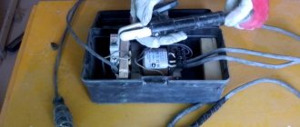
Universal welding machine with toroidal core
Why “multi-welding”? Because this welding transformer (CT) has many important additional functions. If in a traditional “welder”, which has a magnetic circuit assembled from U- and W-shaped plates, there is sometimes nowhere to squeeze in at least one or two auxiliary turns, then in the proposed donut-shaped design there was plenty of free space.
As a result, he is able to cook with AC/DC, charge batteries, melt metal, power electric burners in Skillful Hands circles with safe voltage, and also do a lot of other things. It’s time to even pose the question differently: what other winding and for what purpose would the user of such a CT additionally want to have?!
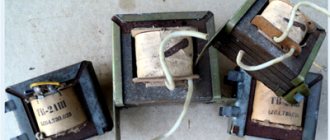
Indeed, the core of the “welder”, which has the shape of a “donut”, called a torus in mathematics and technology, has a great future. Understanding this, but not having at their disposal special industrially manufactured toroidal magnetic cores intended exclusively for transformers, home-made manufacturers are forced to adapt cylindrical ersatz from the stators of old electric motors with a power of 1-1.5 kW for their STs. For this purpose, the housings of electric motors are usually simply broken, the windings laid in the grooves are thrown away as unnecessary, the protrusions of the poles are cut out, and all this is only so that a thickness of copper can be wound onto the resulting blanks (rather reminiscent not of donuts, but of excessively heavy, lopsided, bottomless barrels) to achieve “ super goals" - cook steel with "five"!
I am convinced that there is no need to damage electric motors, even if they have become unusable - a zealous owner will always be able to rewind burnt out windings and replace worn-out bearings. A rebuilt engine is capable of much more...
And for the toroidal magnetic circuit I propose, 5 - 6 kg of scrap transformer steel is enough. Moreover, here you can be content with even the same amount of roofing iron (annealed) as the starting material.
The technology for manufacturing a magnetic circuit from such raw materials is quite simple (Fig. 1). All scrap flat transformer steel is cut with scissors into strips of approximately equal width.
Rice. 1. Formation of a toroidal magnetic circuit: 1 - base of the mold; 2 - external cylinder-formwork (“corolla” of the gear for starting the GAZ-53 car with a starter); 3 - internal cylinder-formwork (60 mm section of steel pipe 100×6, slightly machined, wrapped in two or three layers of paper); 4 - initial mass (plates 60-70 mm wide, cut from scrap from W- and U-shaped transformer steel plates, coated with quick-drying office glue, gum arabic or oil paint and laid over the roof, followed by filling the voids with roofing waste)
Practice shows that most often you have to deal with rectangles 60-70 mm wide or slightly smaller analogues, cut from U- and W-shaped plates. All “iron transformer” waste, as well as roofing waste, are also used. After smearing both sides with some quick-drying glue such as stationery (“liquid” glass), gum arabic, or even cheap oil paint, they are tightly laid with a slight overlap in the formwork (as when pouring a hollow concrete column) from available materials.
In the author's technology, the inner cylinder of the formwork (Fig. 1) is a 60 mm section of steel pipe 100×6 mm. Inside, it must be sharpened slightly into a cone and wrapped (to make it easier to later remove from the “cast” magnetic circuit) with two or three layers of paper strip. And as an external one, a removable “rim” of the gear is used (internal diameter is about 250 mm) - from the starter starting system of the GAZ-53 car.
Of course, other suitable workpieces that can withstand the mechanical stresses that arise during the “casting” of the toroidal magnetic circuit can be used for formwork. And they are considerable, especially when you have to hammer small plates into all the slot holes (preferably, they correspond to the width of the set).
Once the glue has dried, the toroidal core can be considered almost ready. True, it still needs to be made of one-sided rounded half-rings - “half-bubble” - from insulating material. At least from plywood - for better installation of future windings and to avoid short circuits to the sharp edges of the magnetic circuit.
This will also be facilitated by preliminary wrapping of the torus with two or three layers of keeper tape, fiberglass or fabric strip impregnated with drying oil.
Now about the windings of the “welder”. Science asserts, and practice clearly proves, that a transformer operates in the most advantageous mode for it if a current equal to 5 A passes through its windings through 1 mm2 of the cross-section of a copper wire. Under extreme conditions, this figure can increase to 13 A, but at This causes the wires to get very hot and burn out.
For welding, even with a 3-mm electrode, a current of at least 80 A is required. This means that the cross-section of the cores of the copper cable or power (welding) bus must correspond to it. Taken with a substantial margin, for a good-quality homemade welding transformer it is usually in the range from 25 to 35 mm2.
Starting from the already mentioned “minimum welding” 80 A and taking into account the widely practiced ratio of turns of the mains and power windings of approximately 5:1, we find: the current of the mains winding must be at least 16 A. It follows that to install the mains winding it is necessary to take a copper wire with a cross-section not less than 3.2 mm2. However, perhaps the best option is PEV2 with a diameter of 2-2.5 mm.
It is generally accepted (and this is confirmed by practice) that with a “cast” magnetic core having a cross-sectional area along the transformer steel equal to 40 cm2, each turn of the winding will correspond to a voltage of 1 V. Taking into account the possible instability of the power supply, the network winding should be made with a reserve.
The reference point is 250 turns. Moreover, after the 190th, it is advisable to provide (without cutting the wires!) taps every ten turns. Of course, the switch for them must be quite reliable, ensuring good electrical contact in order to avoid large energy losses and strong heating during operation of the CT.
Actually, winding a network winding is a rather difficult operation. It has to be done using long wooden shuttles (Fig. 2). Do everything carefully, avoiding overlapping of turns, formation of knots and damage to the layer of insulating varnish on the wire.
Otherwise, you can expect the appearance of interturn short circuits and overheating of the transformer.
Rice. 2. Laying the turns of the network winding of the “welder” (interlayer insulating gaskets are not shown): 1 - toroidal magnetic circuit; 2 - one-sided rounded half-ring - “half-bubble” made of insulating material (2 pcs.); 3 - fastening insulating gasket (2-3 layers of keeper tape, fiberglass or fabric strip impregnated with drying oil); 4 - network winding wire (PEV2, diameter 2-2.5); 5 - wooden shuttle
If you place the core on two supports with a soft coating (lining), which prevents damage to the wire insulation when winding the CT, then the entire work will take about two hours. It is advisable to finish it “in one pass” so that the winding does not weaken and is as dense as possible, with insulating gaskets between the layers.
After the network has been wound, it’s a good idea to check it at idle. If even after a long period of operation the magnetic circuit with the winding becomes only barely warm, then everything is in order. Significant heating is evidence that either there are few turns, or there is an interturn short circuit (or even a breakdown of the winding to the housing!).
Secondary insulation - welding or power - must be laid on the two-three-layer insulation of the network winding. And this is from 40 to 80 turns of a copper bus or multi-core cable. The latter is preferable for the following reasons: welding sleeves can be immediately made from it; winding is significantly easier; the service life of the welding winding increases while simultaneously simplifying the operating conditions, which is especially important when experimenting with such a CT. In addition, connecting the rectifier is simplified and it becomes possible to effectively regulate the welding current and voltage by performing a simple operation - winding or unwinding turns of the cable.
For homemade welding machines that are not too powerful, the following work schedule is desirable: a minute for welding, two for a technological break to cool the welding machine. The use of small fans gives good results. Probably, even more can be achieved by using the simplest heat-emitting radiators to cool the “welder,” as well as mineral oils that can improve the insulation of the CT windings.
A good welding transformer should have a steeply falling characteristic. This can be achieved by dividing the winding into two equal parts. On one side of the core, half of the network and half of the power windings are wound, and on the other - the rest (and in order not to get confused later - in the same sequence).
Apparently, it is worth recalling that a transformer is a reversible device: if you connect the alternating voltage for which it is designed to any winding, then the others appear to be those for which they were intended. By the way, many radio amateurs do the same when determining the windings in an unknown transformer.
Taking into account the above, it is not at all necessary to wind the network (primary) winding of the vehicle first, and then the welding (secondary) winding on top of it. The order of winding, as well as their serial numbers, is only a condition for faster and more familiar orientation in the circuit diagram of the “welder”. Therefore, if, say, you need to wind one of the windings with a fairly rigid busbar, when laying it you will have to resort to a mallet, then, of course, it is more convenient to place such “copper” first on the core, so as not to damage the more pliable and vulnerable wires of the remaining windings.
And further. If there is enough wire for one winding, and very little for another winding, then first proceed to the one where your capabilities are limited. Because if there is a clear shortage of cable or busbar for the power (welding) winding, but in the presence of powerful diodes-semiconductor valves, it becomes profitable to abandon welding with alternating current in favor of direct current (Fig.
3). In this case, the voltage from the CT, and therefore the number of turns in the welding winding, is sufficient to be kept to a minimum. If the bus has damaged insulation, then it is recommended to first anneal it with cooling in water (the copper will become soft), insulate it with shellac and fiberglass, and only then begin to wind it onto the magnetic circuit.
Fig 3. Circuit design of a welding rectifier with a current regulator for a homemade multi-welding transformer (R1 - a spiral of nichrome wire with a diameter of 3-5 mm with a movable knife-shaped contact)
Do-it-yourselfers often have difficulties connecting the power cable to the product being welded: either the contact is poor or there is nothing to “grab” to. Two types of devices can help in such situations (Fig. 4): a magnetic contact and an alligator clip. Both homemade products are extremely easy to make, fast and easy to attach.
If there is no proper contact, it is enough to rub them a little on the part.
Rice. 4. Options for devices for ground contact - magnetic (a) and alligator clip (b): 1 - welding cable; 2 - handle; 3 — steel plate; 4 - ring magnet - “stuck”; 5- screw (quantity and location - at the installation site); 6 - half of a homemade “toothed jaw” clothespin (from a piece of steel pipe of a suitable size, 2 pcs.); 7 — steel axle, riveted on both sides; 8 - spring.
It’s also a good idea to equip the CT network winding with a standard AP automatic machine, designed for at least 30 A - with its help it is convenient to turn off the transformer during pauses between welding. This will significantly save electricity, create favorable conditions for timely cooling of the device, and make work safer.
Well, the presence of a powerful rectifier (Fig. 3) will allow, as already noted, to use the resulting unit when charging batteries or organizing multi-station power supply, for example, low-voltage soldering irons and electric burners in “Skillful Hands” school clubs. Moreover, such a unit is truly indispensable, for example, when performing galvanic work at home or starting a car in cold conditions.
It is very interesting and promising to equip the CT with an additional winding containing only one full turn of an annealed copper busbar 5x50 mm or a thick stranded copper cable with a diameter of about 20 mm (with ends made of sections of thick-walled copper pipe). As practice has shown, with the help of such a winding it is possible to perform hot open forging, hardening and bluing, soldering and surfacing; bending of metal strip, pipe, thick steel rod, round timber, brittle wire; casting of tin, zinc, lead; unscrewing “stuck” bolts, studs and nuts; spot welding, hot fit and a number of other operations.
How to smoothly regulate the current? Yes, at least in the way mentioned above - by adjusting the power (cable) winding. When winding part of it from the magnetic circuit, the voltage decreases with a simultaneous increase in the current from the CT, but, in particular, the conditions for ignition of the arc worsen.
And vice versa: rewinding the cable leads to an increase in the transformed voltage with a simultaneous decrease in the current supplied to the load. In this case, the electric arc ignites better.
Or another option, when the welding cable is connected to the product not directly, but through several turns of wire with high resistance (for example, nichrome). How many resistant turns are there are so many stages of welding current adjustment. The arc is ignited in almost the same way in all cases.
The CT current can be adjusted using a combined valve made of transformer steel and non-ferrous metal. In this case, a cross cut is made on the magnetic core.
Plumbers, motorists, repairmen and just those who like to do things with their own hands, this “welder” with such universal properties is for you.
R. KRAVTSOV, Yeisk, Krasnodar region. Modeler-constructor 2004 No. 2.
What are the advantages of a toroidal transformer core?
Recall that the core or magnetic circuit of the toroidal transformer 220 is manufactured in the form of a ring. And this is almost an ideal form in physical terms. For its production, tape-shaped permalloy is most often used in production, and the material consumption is small, and rejection and trimming on the conveyor is reduced. At the second stage of the sequential manufacturing of the transformer, a winding is applied to its core and distributed evenly without flaws over a given surface. The length of the winding wires is short, so the resistance force in the segment is also reduced. And this provides the toroidal transformer with high efficiency. The core of the toroidal transformer itself plays an important role in this.
Let's consider how to calculate the power of a transformer
First, we determine the cross-section of the base. The magnetic core must not only withstand a magnetic field of a certain intensity, it also dissipates the generated heat. There is a simplified method for calculating the cross-sectional area in cm². It is equal to the square root of the required power value in watts.
This is the maximum value; a real transformer should have a margin of +50%. Otherwise, the core will fall into the region of magnetic saturation, which will lead to sudden local heating. For toroidal cores, a margin of 30% of the calculated area is sufficient.
Next, you need to know how to determine the wire parameters for the windings in order to ensure the design power of the transformer. The first value is the number of turns per volt (we are talking about the primary winding).
To do this, we will use a simple formula: divide the constant 60 by the cross-sectional area in cm². For example, the cross-section of the magnetic circuit is 6 cm². This means that for every volt of input voltage, 10 turns of wire are required. That is, with a power supply of 220 volts, the primary winding will consist of 2200 turns.
The calculation of secondary windings is made in proportion to the transformation ratio. If 20 volts of output are required, at a constant of 10 turns per volt, 200 turns of secondary winding will be required. This is an absolute value, excluding load losses. We obtain the true number of turns by multiplying the value by 1.2.
Before winding the transformer, you need to know the cross-section of the wire. The minimum wire diameter is calculated using the formula: D=0.7*√I
Important! The diameter of the conductor is measured without taking into account the thickness of the insulating varnish. It must be washed off with acetone at the measurement site. This is true for wires with a small cross-section.
√I – square root of the current value in amperes
There is no need to skimp on wires. A smaller diameter does not dissipate heat well and the winding may burn out. The thinner the wire, the higher the resistance. Possible power losses and reduction in design characteristics.
How it works
The design is similar to the armored one, the magnetic field is single-turn, and accordingly the power is less. It also has a collapsible design. The efficiency of using the surface of the magnetic circuit is not higher than 40%.
Expert opinion
It-Technology, Electrical power and electronics specialist
Ask questions to the “Specialist for modernization of energy generation systems”
Let's look at how to calculate the power of a transformer. Toroidal cores are made of magnetic coiled transformer steel with very low loss levels and high saturation induction. Ask, I'm in touch!
What must be taken into account when calculating a toroidal transformer
In order to apply the standard physical formula, you first need to know the parameters of the voltage that will be supplied to the primary winding of the product (symbol for the formula - U), the outer and inner diameter of the core or magnetic circuit (symbol for calculations - D and d), and, The main thing is not to forget about the thickness of the magnetic circuit - H.
An important indicator is the area of the core window (previously recorded in the records - S). The intensity of excess heat removal largely depends on it. These core gap areas range from 80 to 100 cm, and the cross-section is half as large.
Just in case, let us remember the calculation formulas in the article: S0 = * d2 / 4., Sc = H * (D – d)/2.
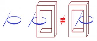
Complete limitation of the B field by toroidal inductors
| This article provides insufficient context for those unfamiliar with the subject . |
In some cases, the current in the winding of a toroidal inductor contributes only to B
field inside the windings and does not contribute to the magnetic
B
field outside the windings. This is a consequence of symmetry and Ampere's law of rotation.
Sufficient conditions for complete internal confinement of field B
| Rice. 1. Coordinate system. The Z axis is the nominal axis of symmetry. The X axis is chosen arbitrarily to correspond to the starting point of the winding. ρ is called the radial direction. θ is called the circumferential direction. | Rice. 2. Axisymmetric toroidal inductor without circumferential current. |
The absence of circumferential current [4] (the path of the circumferential current is indicated by a red arrow in Figure 3 of this section) and the axisymmetric arrangement of conductors and magnetic materials. [4][5][6] are sufficient conditions for the complete internal constraint of B
field.
(Some authors prefer to use the HOUR
field.)
Because of symmetry, the flux lines B must form circles of constant intensity centered on the axis of symmetry. The only B flux lines that carry any current are those inside the toroidal winding. Therefore, from Ampere's winding law, the field strength B must be zero outside the windings.[6] Rice.
3. Toroidal inductor with circumferential current. Figure 3 in this section shows the most common toroidal winding. This does not meet both requirements for complete B field limitation. When viewed from the axis, sometimes the winding is inside the core and sometimes outside the core. In the near region it is not axisymmetric. However, at points located at a distance several times greater than the distance between the windings, the toroid actually appears symmetrical.[7] The problem of circumferential current remains. No matter how many times the winding wraps around the core and how thin the wire is, this toroidal inductor will still include a single-coil loop in the plane of the toroid. This winding will also produce and be susceptible to E
field in the plane of the inductor.
Figures 4-6 show various methods for neutralizing the circumferential current. Figure 4 is the simplest and has the advantage that the return wire can be added after purchasing or assembling the inductor.
| Rice. 4. Circumferential current opposing the return wire. A white wire runs between the outer rim of the inductor and the outer part of the winding. | Rice. 5. Circumferential current opposing the return winding. | Rice. 6. Circumferential current opposing the divided return winding. |
E field in the toroid plane
| Rice. 7. A simple toroid and the generated E-field. Excitation of ±100 volts is acceptable. | Rice. 8. Voltage distribution with reverse winding. Excitation ± 100 Volts is allowed. |
There will be a potential distribution along the winding. This may lead to E
-Field in the plane of the toroid, as well as the susceptibility to
E
field in the plane of the toroid, as shown in Figure 7. This can be reduced by using a return winding, as shown in Figure 8. In this winding, each place where the winding crosses itself, two parts will have equal and opposite polarity, which significantly reduces the field E generated in the plane.
Toroidal inductor/transformer and vector magnetic potential
Main article: Magnetic vector potential
Shows the development of the magnetic vector potential around a symmetrical toroidal inductor.
See Feynman Chapter 14.[8] and 15[9] for a general discussion of the magnetic vector potential. See Feynman page 15-11. [10] for a diagram of the magnetic vector potential around a long thin solenoid, which also exhibits complete internal limitation B
field, at least in the infinite limit.
B A
the field is exact using the assumption b f A = 0 {displaystyle bf {A} = 0} . This would be true under the following assumptions:
- 1. Coulomb gauge is used
- 2. Lorentz sensor is used and there is no charge distribution, ρ = 0 {displaystyle ho = 0,}
- 3. Lorentz sensor is used and zero frequency is assumed
- 4. A Lorentz sensor is used and a non-zero frequency low enough to neglect 1 c 2 ∂ ϕ ∂ t {displaystyle {frac {1} {c^{2}}} {frac {partial phi} {partial t}}} is assumed.
Number 4 will be assumed for the rest of this section and can be referred to as the "quasi-static state".
Although an axisymmetric toroidal inductor without circumferential current completely limits B
the field inside the windings
And
the field (magnetic vector potential) is not limited.
Arrow No. 1 in the figure depicts the vector potential on the axis of symmetry. The radial current sections a and b are at equal distances from the axis, but are directed in opposite directions, so they cancel. Segments c and d are canceled in the same way. Virtually all radial current segments are cancelled. The situation is different with axial currents. The axial current on the outside of the toroid is directed downward, and the axial current on the inside of the toroid is directed upward. Each segment of the axial current on the outer side of the toroid can be associated with an equal but oppositely directed segment on the inner side of the toroid. The segments inside are located closer to the axis than the segments outside, so there is a net upward component of the A
field along the axis of symmetry.
Representation of the fields of magnetic vector potential (A), magnetic flux (B) and current density (j) around a toroidal inductor of circular cross-section. Thicker lines indicate field lines with higher average intensity. The circles in the cross section of the core represent the flow B coming out of the picture. Plus signs on another section of the core indicate flux B. Div A
= 0 was accepted.
Since the equations ∇ × A = B {displaystyle abla imes mathbf {A} = mathbf {B}} , and ∇ × B = μ 0 j {displaystyle abla imes mathbf {B} = mu _ {0} mathbf {j}} ( under the assumption of quasi-static conditions, i.e. ∂ E ∂ t → 0 {displaystyle {frac {partial E} {partial t}} ightarrow 0} ) of the same shape, then the lines and contours of A
is to
B
as the lines and contours
of B
are to
j
.
Thus, the image of the A
field around a
B
loop (as in a toroidal inductor) is qualitatively the same as
the B
field around a current loop.
The figure on the left is an artist's image of A
field around a toroidal inductor.
Thicker lines indicate paths with higher average intensity (shorter paths have higher intensity, so the path integral remains the same). The lines are simply drawn to look good and give the overall appearance of the A
field.
Toroidal action of a transformer in the presence of full field limitation B
In E
and
B
fields can be calculated from
A
and ϕ {displaystyle phi,} (scalar electric potential) fields
B = ∇ × A. {displaystyle mathbf {B} = abla imes mathbf {A}.} [11] and : E = − ∇ ϕ − ∂ A ∂ t {displaystyle mathbf {E} = -abla phi — {frac {partial mathbf {A}} {partial t}}} [11] and so, even if the area outside the windings is devoid of the B
field, it is filled with a non-zero
E
field. The quantity ∂ A ∂ t {displaystyle {frac {partial mathbf {A}} {partial t}}} is responsible for the desired magnetic field coupling between the primary and secondary windings, while the quantity ∇ ϕ {displaystyle abla phi,} is responsible for the undesirable connection of the electric field between the primary and secondary windings. Transformer designers try to minimize electric field coupling. For the rest of this section, ∇ ϕ {displaystyle abla phi,} will be assumed to be zero unless otherwise noted.
Stokes' theorem applies[12] so that the path integral A
is equal to the applied
B
, just as the path integral of
B
is equal to a constant times the applied current
Path integral E
along the secondary winding gives the induced emf of the secondary winding (electromotive force).
EMF = ∮ p a t h E ⋅ d l = − ∮ p a t h ∂ A ∂ t ⋅ d l = − ∂ ∂ t ∮ p a t h A ⋅ d l = − ∂ ∂ t ∫ s you r a c e B ⋅ ds {displaystyle mathbf {EMF} = oint _ {path} mathbf {E} cdot {m {d}} l = -oint _ {path} {frac {partial mathbf {A}} {partial t}} cdot {m {d }} l = — {frac {partial} {partial t}} oint _ {path} mathbf {A} cdot {m {d}} l = — {frac {partial} {partial t}} int _ {surface} mathbf {B} cdot {m {d}} s}
where it is said that the emf is equal to the rate of change with time of the flux B contained in the winding, which is the usual result.
Toroidal transformer Poynting vector coupling from primary to secondary with full field limitation B
In this figure, the blue dots indicate where flux B from the primary current exits the image, and the plus signs indicate where it enters the image.
Explanation of the picture
This picture shows half of a toroidal transformer. Quasi-static conditions are assumed, so the phase of each field is the same everywhere. The transformer, its windings and everything else are located symmetrically relative to the axis of symmetry. The windings are such that there is no circumferential current. Requirements for complete internal insulation B
field due to the primary current.
The core and primary winding are represented by a gray-brown torus. The primary winding is not shown, but the winding current on the cross-sectional surface is shown as gold (or orange) ellipses. In B
, the field caused by the primary current is completely confined to the area surrounding the primary winding (i.e., the core).
The blue dots on the left cross section indicate that line B
core flow exits the left cross section.
In the other section, blue plus signs indicate that B
flow is entering there.
In E
, the field arising from the primary currents is shown by green ellipses.
The secondary winding is shown as a brown line running straight along the axis of symmetry. In normal practice the two ends of the secondary winding are connected together by a long wire which is located a considerable distance from the torus, but to maintain absolute axial symmetry the whole apparatus is treated as being inside a perfectly conducting sphere with a secondary wire "grounded" to the inside of the sphere at each end. The secondary winding is made of resistance wire, so there is no separate load. In E
, the field along the secondary causes a current in the secondary (yellow arrows), which causes
a B
field around the secondary (shown by blue ellipses).
This B
field fills the space, including inside the transformer core, so the end result is a continuous non-zero
B
field from the primary to the secondary unless the secondary circuit is open.
The cross product of the E
field (derived from the primary currents) and
the B
field (derived from the secondary currents) forms the Poynting vector, which is directed from the primary to the secondary.
Is it possible to make a toroidal core yourself?
A geometrically correct toroidal core is not so easy to reproduce independently, especially by novice inventors. Firstly, you need to have at your disposal a special permalloy tape, also sometimes called transformer steel. Secondly, familiarize yourself with the rules for forming a torus of rectangular cross-section. The actions are familiar - you need to roll the material into a roll. Actions are consistent and careful, if necessary, go back a step.
A special wooden shuttle with technical semicircular cutouts can be a help in this matter, especially if you need to calculate how much material is needed for winding. The wire for the winding is always taken with an allowance. Recommended reserve is 20-30%.
Thus, it becomes clear that a toroidal transformer can give a head start to other existing power elements. And all because it is simple, reliable and functional. The existing core is created in an advantageous form, which is easy to work with not only at the stage of product manufacture, but also during installation, operation and repair. It is possible to make such a transformer yourself, but this will require perseverance, knowledge, the desire to create a product, the desire to make calculations and look for alternatives.