It is generally accepted that the Laval nozzle is a technical device designed exclusively for accelerating gas flows to supersonic speeds.
Let's take a picture from the Wikipedia article. (Fig. 1.), which schematically shows the cross-section of the nozzle, as well as the dynamics of pressure, temperature and gas flow velocity along the nozzle axis.
Fig.1 Illustration of the operation of the Laval nozzle. As the gas moves through the nozzle, its absolute temperature T and pressure P decrease, and its speed V increases. M is the Mach number.
The narrowing part of the nozzle is called a confuser, and the expanding part is called a diffuser. I would like to draw your attention to the ratio of the lengths of the confuser and diffuser. The diffuser is longer than the confuser. And although no one pays attention to this fact in various sources, I think that this is an important parameter, the value of which must be observed. Moreover, if you design a Laval nozzle for gas and steam flow, then, indeed, the length of the confuser should be less than the length of the diffuser.
I don’t know how scientists explain this fact, but as a Russian amateur, I can assume that this is connected with certain gas laws. If you compare the Laval nozzle and the most ordinary internal combustion engine (internal combustion engine), you will notice that there is a certain analogy between them - alternating phases of compression and rarefaction, which ultimately allows the internal energy of gas (fuel) to be released. There are 4 phases in an internal combustion engine - two isothermal and two adiabatic. There appear to be only two phases in a Laval nozzle - adiabatic compression and isothermal expansion.
Compression is carried out in a confuser. And for an adiabatic process it must be short. Isothermal expansion occurs in a diffuser, therefore, to bring the process closer to isothermal, the diffuser must be long, much longer than the confuser.
Of course, it is necessary to talk about the identity of compression and rarefaction of gas along the central axis of the Laval nozzle with a certain degree of convention, since the transience of the processes in it does not allow the process of heat exchange between the gas stream and the environment. But who talks about the environment? After all, it is necessary, first of all, to explain where the fuel, during its combustion, gets the energy that allows it to throw satellites and spacecraft into Earth orbit and even further? Smart people claim that this is the so-called internal energy of the fuel, but the mechanism of this process itself is wisely hushed up, referring to certain laws of nature discovered experimentally.
As an amateur, I can only assume that the internal energy of the fuel is a response of the ethereal and gaseous medium to the gas flow moving along the Laval nozzle. First, this combined medium is subjected to adiabatic compression, then to isothermal expansion. And in response, the ether-atomic mixture responds with the release of infrared radiation and various types of shock waves. And this answer largely depends on the composition of the gas. Different gases give different responses. But with any gas, it is important to take into account the participation of the ethereal medium in this process.
The Laval nozzle can even be considered as a simple heat pump option.
By connecting two Laval nozzles, Shesterenko got his own nozzle. Here you can get acquainted with one of his patents. And here with another patent. If desired, any user can find more Shesterenko patents for nozzles and supernozzles of various designs. I think that in recent years no one has openly declared that they use Shesterenko attachments in certain production processes. But it seems that these structures are already actively working all over the world, including in Russia.
Some inventors tried to use the Laval nozzle in heat generators as a cavitator. As you know, water at high speeds begins to soar directly in the flow, forming many small bubbles of steam, which, when collapsing, give rise to a lot of interesting phenomena, one of which is heating of water. True, when using classic Laval nozzles, which work well in gas flows, cavitation in a water flow led to a weak superunit effect - 120-200%. This, of course, required a revision of some principles of physics, but on the other hand, such a power amplification factor (PAF) did not allow us to hope for the creation of powerful energy generators and always carried the threat that there would be someone who wanted to criticize such a modest result, attributing it all to the ignorance of the discoverers and imperfection of measurement methodology or technology. It was precisely under this scenario that the first experiments on cold nuclear fusion were criticized. The same reaction was to the creators of the first heat generators, for example, Potapov. Therefore, for water flows a completely different form of Laval nozzles was required. And such attempts were made.
Those interested can obtain the rest of the information directly from the patent itself. It is important for us to understand that for easily boiling liquids, the Laval nozzle must have a design different from those that work well with gas flows. And, most likely, for each specific gas or liquid, as well as for the selected operating modes, you should create your own Laval nozzle.
A Laval nozzle for a low-boiling liquid, such as water, must take into account the fact that the volume of mass increases in the case of the formation of two phases in the liquid - liquid and vapor. For steam occupies hundreds of times more volume at a pressure of 1 atmosphere. For water, this figure is approximately 600-700. Therefore, to double the flow volume, it is required that a small part of the liquid, literally 1-3%, turns into steam. In this case, pressure increases and the force of the mixture increases. And this result comes for nothing, as a manifestation of certain laws of Nature - the laws of phase transition, the role of the Ether in which has simply not yet been studied.
It is for this reason that I became confident that the Laval nozzle is a super-unit device that allows you to use not only the calorific value of the fuel, as is the case in an internal combustion engine, Diesel or Stirling engine, but also the response of the environment, the manifestation of which is not only additional infrared radiation and shock waves, but also a lot of other interesting effects.
Operating principle of the Laval nozzle:
The illustration below shows the operation of a Laval nozzle.
As the gas moves through the nozzle, its absolute temperature T and pressure P decrease, and its speed V increases. The internal energy of the gas is converted into the kinetic energy of its directed motion. The efficiency of this conversion in some cases (for example, in the nozzles of modern rocket engines) can exceed 70%. M – Mach number (speed of sound).
In the tapering, subcritical section of the nozzle, gas movement occurs at subsonic speeds (M gas reaches sonic speed (M = 1). In the expanding, supercritical section, the gas flow moves at supersonic speeds (M > 1).
The narrowing part of the nozzle is called a confuser, and the expanding part is called a diffuser. The diffuser is always longer than the confuser. Sometimes the length of the diffuser exceeds the length of the confuser by 250 times. Lengthening the diffuser helps to increase the speed of gas flow from the nozzle, and, accordingly, the thrust.
© Photo //www.pexels.com, //pixabay.com, //ru.wikipedia.org/wiki/Laval_Nozzle
outflow rate calculation work outflow from a Laval nozzle Laval nozzle principle of operation drawing buy temperature for air with your own hands formulas for water calculator Wikipedia dimensions
Source
see also
- Mechanically driven ventilation is
- Do-it-yourself underground ventilation in a wooden house
- Fresh air valve for plastic windows
- DIY car seat ventilation
- Installing ventilation in the house
- Ventilation and air conditioning system in a private house
- Ventilation in the bathhouse under the floor
- Interior ventilation Renault Logan
- Air valves for ventilation
- Kindergarten ventilation
- Kamenev pn heating and ventilation part 2
Operating principle of Laval nozzle
As the gas moves through the nozzle, its absolute temperature T and pressure P decrease, and its speed V increases.
The internal energy of the gas is converted into the kinetic energy of its directed motion.
The efficiency of this conversion in some cases (for example, in the nozzles of modern rocket engines) can exceed 70%. M – Mach number (speed of sound).
In the tapering, subcritical section of the nozzle, gas movement occurs at subsonic speeds (M 1).
The narrowing part of the nozzle is called a confuser, and the expanding part is called a diffuser. The diffuser is always longer than the confuser. Sometimes the length of the diffuser exceeds the length of the confuser by 250 times. Lengthening the diffuser helps to increase the speed of gas flow from the nozzle, and, accordingly, the thrust.
Elementary theory of the Laval nozzle
The influence of compressibility on the shape of current tubes.
Let us consider how compressibility affects the shape of current tubes during steady gas motion. Let us assume that the current tube is thin and the characteristics of motion at different points of each section are the same. Let be the area of an arbitrary cross-section of the current tube, and the cross-section is perpendicular to the speed of movement of the gas particles.
If the fluid is homogeneous and incompressible, then from the continuity equation it follows that the mass and volume flow rates through the flow tube are constant, i.e. ; And
those. the higher the speed, the smaller the cross section.
For a compressible fluid, density depends on speed. For reversible adiabatic flows of a perfect gas
Substituting this expression into (7.39), one can obtain the dependence and find the shape of the current tubes. The graph is shown in Fig. 7.15.
Let us project the Euler equation of motion onto the streamline and for steady motion
where along the current line. For adiabatic movements, as stated earlier, it coincides with the speed of sound, defined as (in the general case, the value is different from the speed of sound, but subsequently for non-adiabatic movements it plays the role of the speed of sound). Thus, along the streamline we have
Thus, in a subsonic flow, the cross-section of the current tube decreases with increasing speed. The maximum speed that can be achieved with subsonic flow in a tapering current tube is equal to the speed of sound.
A nozzle consisting only of a tapering section (Fig. 7.17) is called a simple nozzle. The highest speed that can be achieved by releasing gas adiabatically through a simple nozzle is equal to the speed of sound, which is achieved in the narrowest section (at the nozzle exit).
Let us consider how the mass flow of gas through the nozzle depends on the pressure ratio at constant values of temperature and pressure in the vessel, when there is no heat exchange between the gas and the environment.
When, based on (7.43), we obtain that (point in Fig. 7.19).
The critical flow rate, according to (7.30) and (7.42), will be equal to
With a further decrease in backpressure, the flow inside the nozzle ceases to change, and the flow rate also remains unchanged and equal to the critical one. The constancy of the flow rate is explained by the fact that weak disturbances (and therefore small changes in back pressure) propagate through the particles of the medium at the speed of sound. Therefore, when the critical mode is reached (when the particles themselves at the nozzle exit have a speed equal to the speed of sound), the particles inside the nozzle “do not know” what is happening outside the nozzle (disturbances are carried away by the flow of gas particles, and the flow seems to block the nozzle) .
Comment. A change in back pressure will affect the flow of gas outside the nozzle: in a free jet outside the nozzle, the speed may become supersonic as it decreases, but the flow in the free jet will not be uniform (the speed in the flow changes significantly across the cross section of the jet).
When a compressed gas flows out of a thin hole, the flow speed, as shown above, cannot be greater than the speed of sound. Achieving supersonic exhaust speed, as shown by the experiments of G. Laval (1845 - 1913), is achieved only by changing the configuration of the hole. In his experiments, the outflow speed exceeded the speed of sound when a special nozzle was installed at the outlet of the vessel, which was later called the Laval nozzle.
Laval nozzle
Laval nozzle
- a technical device that accelerates a gas flow passing through it to supersonic speeds. Widely used on some types of steam turbines and is an important part of modern rocket engines and supersonic jet aircraft engines.
The nozzle is a channel narrowed in the middle. In the simplest case, such a nozzle may consist of a pair of truncated cones connected by narrow ends. Efficient nozzles of modern rocket engines are profiled based on gas dynamic calculations.
The nozzle was proposed in 1890 by Swedish inventor Gustaf de Laval for steam turbines.
Goddard's preference for the use of Laval nozzles for rockets is confirmed by the drawing in the description of the invention in US Patent 1,102,653, dated July 7, 1914, for a two-stage solid propellant rocket, claimed in October 1913.
Recommendations
| Wikimedia Commons has media related to Convergent-divergent nozzles . |
- K.J. Clark and B. Carswell (2007). Principles of astrophysical hydrodynamics
(1st ed.). Cambridge University Press. p.226. ISBN 978-0-521-85331-6. - https://books.google.it/books?id=PmuqCHDC3pwC&pg=PA396&lpg=PA396&dq=nozzle+Ernst+Koerting&source=bl&ots=odOCii_n0h&sig=ACfU3U1I2XcTbRt3HVMHDsqyvT91q2P3HA&hl=nl&sa=X&ved=2ahUKEwixn KCX8OrqAhWylYsKHb7zA1s4ChDoATAHegQIChAB#v=onepage&q=nozzle%20Ernst%20Koerting&f=false
- See:
- Belgian Patent No. 83,196 (Issue: 29 September 1888)
English Patent No. 7143 (Issue: April 29, 1889)
- de Laval, Carl Gustav Patrick, "Steam Turbine," US Patent No. 522066 (Filed: May 1, 1889; Issued: June 26, 1894)
- Theodore Stevens and Henry M. Hobart (1906). Steam turbine
. MacMillan Company. pp. 24–27. Available online here on Google Books. - Robert M. Neilson (1903). Steam turbine
. Longmans, Green and Company. pp.102–103. Available online here on Google Books. - Garrett Scaife (2000). From Galaxies to Turbines: Science, Technology and the Parsons Family
. Taylor and Francis Group. 197. Available online here in Google Books. - Richard Nuckey Equation 12.
- Robert Browning Equation 1.22.
- George P. Sutton (1992). Elements of Rocket Propulsion: An Introduction to Rocket Design
(6th ed.). Wiley-Interscience. item 636. ISBN 0-471-52938-9. - Hall, Nancy. "Mass flow lock." NASA
. Retrieved May 29, 2022.
Gas flow rate from the nozzle
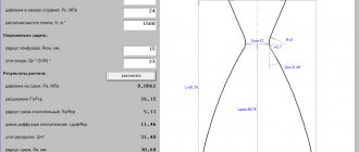
From the equation of state of an ideal gas and the energy balance in the gas flow, the formula for calculating the linear velocity of gas outflow from a Laval nozzle is derived: [1]
(4)
— Gas velocity at the nozzle exit, m/s, — Absolute gas temperature at the inlet, — Universal gas constant J/(kilomol K), — molar mass of gas, kg/kilomol, — Adiabatic exponent, — Specific heat capacity at constant pressure, J/(kilomol K), — Specific heat capacity at constant volume, J/(kilomol K) TO),
Application
In industry and in everyday life, cavitation heat generators have found implementation in a wide variety of fields of activity. Depending on the tasks assigned, they are used for:
- Heating – inside the installations, mechanical energy is converted into thermal energy, due to which the heated liquid moves through the heating system. It should be noted that cavitation heat generators can heat not only industrial facilities, but also entire villages.
- Heating running water - a cavitation unit is capable of quickly heating liquid, due to which it can easily replace a gas or electric water heater.
- Mixing of liquid substances - due to rarefaction in the layers to obtain small cavities, such units make it possible to achieve the proper quality of mixing of liquids that do not naturally combine due to different densities.
Operating in the environment
When a Laval nozzle operates in a non-empty medium (most often we are talking about the atmosphere), supersonic flow can only occur if the excess gas pressure at the nozzle inlet is sufficiently large compared to the ambient pressure.
When a supersonic flow occurs, the gas pressure at the nozzle exit may be even less than the ambient pressure (due to overexpansion
gas moving through the nozzle).
Such a flow can remain stable, since the ambient pressure (as long as it is not much higher than the gas pressure at the nozzle exit) cannot propagate against the supersonic flow. [ source not specified 980 days
]
In the general case, the specific impulse of a Laval nozzle (when operating both in a medium and in a vacuum) is determined by the expression:
(5)
Here
— the speed of gas outflow from the nozzle, determined by formula (4); — nozzle cut area; — gas pressure at the nozzle exit; — ambient pressure; — second mass flow rate of gas through the nozzle.
From expression (5) it follows that the specific impulse and, accordingly, the thrust of the rocket engine in vacuum (at
) is always higher than in the atmosphere.
This is reflected in the characteristics of real rocket engines: usually for engines operating in the atmosphere, two values are indicated for specific impulse and thrust - in vacuum
and
at sea level
(for example, RD-107).
Dependence of engine characteristics on gas pressure at the nozzle exit
is more complex in nature: as follows from equation (4), it increases with decreasing , and the addition decreases and becomes negative.
At a fixed gas flow rate and pressure at the nozzle inlet, the value
depends only on the cut area of the nozzle, which is usually characterized by a relative value -
the degree of expansion
of the nozzle - the ratio of the final cut area to the critical section area. The greater the degree of expansion of the nozzle, the lower the pressure, and the greater the gas flow rate.
Considering the relationship between the pressure at the nozzle exit and the ambient pressure, the following cases are distinguished. [2]
The above explains the fact that rocket engines operating in dense layers of the atmosphere, as a rule, have a lower degree of expansion than engines operating in vacuum. For example, the F-1 engine of the first stage of the Saturn 5 launch vehicle has an expansion ratio of 16:1, and the RL 10B-2 engine, used by NASA on interplanetary probe accelerators, has an expansion ratio of 250:1.
The desire to achieve efficient engine operation both on Earth and at altitude forces designers to look for technical solutions to achieve this goal. One of these solutions was a movable nozzle nozzle
- a “continuation” of the nozzle, which docks to it once the rocket reaches the rarefied layers of the atmosphere, thus increasing the degree of expansion of the nozzle. The operation diagram of the nozzle is shown in the figure on the right. This scheme was practically implemented, in particular, in the design of the NK-33-1 engine.
The problem of optimizing the degree of expansion of the nozzle is also very relevant in the development of aviation jet engines, since the aircraft is designed for flights in a wide range of altitudes, and the efficiency and, consequently, the flight range strongly depend on the specific impulse of its engines. Modern turbojet engines use adjustable nozzles
Laval.
Such nozzles consist of longitudinal plates that can move relative to each other, with a special mechanism with a hydraulic or pneumatic drive, which allows you to change the area of the exit and/or critical sections in flight, and thus achieve the optimal degree of expansion of the nozzle when flying at any altitude . Regulation of the flow area is usually performed automatically by a special control system. The same mechanism allows, at the command of the pilot, to change within certain limits the direction of the jet stream, and therefore the direction of the thrust vector
, which significantly increases the maneuverability of the aircraft.
Advantages and disadvantages
Compared to other heat generators, cavitation units have a number of advantages and disadvantages.
The advantages of such devices include:
- A much more efficient mechanism for generating thermal energy;
- Consumes significantly less resources than fuel generators;
- Can be used for heating both low-power and large consumers;
- Completely environmentally friendly - does not emit harmful substances into the environment during operation.
The disadvantages of cavitation heat generators include:
- Relatively large dimensions - electric and fuel models have much smaller dimensions, which is important when installed in an already used room;
- Great noise due to the operation of the water pump and the cavitation element itself, which makes it difficult to install in domestic premises;
- Ineffective ratio of power and performance for rooms with small square footage (up to 60 m2 it is more profitable to use a gas, liquid fuel or equivalent electrical power with a heating element).\