Principles of dimensional RCD
During dimensional processing, the usual mechanical cutters and abrasives act as a direct tool of influence. The key difference between this method is the energy source that powers the tool. An ultrasonic current generator operating at frequencies of 16–30 kHz acts in this capacity. It provokes vibrations of the same abrasive grains at an ultrasonic frequency, which ensures the characteristic quality of processing. Moreover, it should be noted that there are a variety of types of mechanical effects. This is not only the usual cutting and grinding elements, but also deformation of the structure while maintaining its volume. Moreover, ultrasonic sizing ensures minimal removal of workpiece particles even during cutting. The grains that impact the material punctuate microparticles that do not affect the design of the product. In essence, the destruction of the structure by extraction does not occur, but uncontrolled propagation of cracks may occur.
Operating principle of installations for generating ultrasonic vibrations
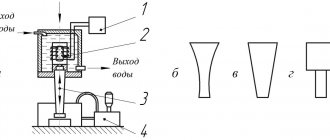
Ultrasonic installations used for dimensional processing of materials (Fig. 1) contain:
- electrical oscillation generator;
- acoustic transducer;
- ultrasonic oscillatory system, supply and removal system of coolant and suspension with abrasive.
Figure 1 – Diagram of the installation for ultrasonic dimensional processing (a) and diagram of the concentrators: exponential (b), conical (c) and stepped (d): 1 – generator; 2 – acoustic transducer; 3-ultrasonic oscillatory system; 4 – system for supplying coolant and suspension with abrasive
Ultrasonic generators are designed to convert electric current at industrial frequency (50 Hz) into high frequency current.
The acoustic transducer is designed to convert electrical high-frequency vibrations into mechanical ones. For dimensional processing purposes, magnetostrictive and piezoelectric transducers are predominantly used.
Magnetostrictive converters use the effect of longitudinal magnetostriction, which consists in changing the length of a core of ferromagnetic material placed in a magnetic field. The simplest magnetostrictive converter is a core made in the form of a rod or frame with an excitation winding. When an alternating electric current passes through the winding, an alternating magnetic field is induced in the core, and elastic deformations occur, causing longitudinal vibrations of the core.
To reduce losses due to Foucault currents, metal cores are assembled from stamped thin plates or wound from thin tape. Magnetostrictive converters are water-cooled. Their maximum electroacoustic efficiency in the frequency range 20...30 kHz is 50...70%. As the oscillation frequency increases, its value decreases.
Magnetostrictive converters are also made from ferrites. They have virtually no eddy current losses. Therefore, ferrite cores are made monolithic. To magnetize them, plates of ferrite permanent magnets are used, which are inserted or glued into the magnetic circuit of the converter. The electroacoustic efficiency of ferrite transducers reaches 80...85%. They do not require high supply voltage or forced water cooling.
Piezoelectric transducers use the piezoelectric effect, the essence of which is that in crystals with a certain type of lattices, under the influence of an electric current, internal voltages arise that are proportional to the electric field strength. As a result, the dimensions of the crystal change in accordance with the change in electric current.
All piezoelectric materials are divided into natural and artificial. Natural ones are quartz, seignette salt, tourmaline; artificial – ceramics of barium titanate TsTS-19 and lead titanate TsTS-23.
Quartz transducers are expensive and their sizes are limited. Piezoceramics are much cheaper and require lower exciting voltages.
The oscillatory system is designed to transmit vibrations occurring in the converter to the working units of the installation and, ultimately, to the surface being processed. The oscillatory system includes: a waveguide, a concentrator, and an instrument.
A waveguide is a rod or pipe of constant cross-section that connects an acoustic transducer to a concentrator.
The concentrator is designed to increase the amplitude of the mechanical vibrations of the instrument by ensuring resonance of the frequencies of the vibrator (magnetostrictive or piezoelectric) with the actuating instrument. The main forms of concentrators are presented in Figure 1 b, c, d.
Differences from plasma processing technology
In terms of processing quality, ultrasonic and plasma methods have many similarities, providing the possibility of high-precision cutting. But there is also a significant difference between them in the principle of operation. Thus, if ultrasonic treatment involves intense impact on abrasive powder from a trimming tool with the energy support of an electric wave generator, then the plasma processing method uses ionized gas charged with ions and electrons as a working medium. That is, ultrasonic and plasma processing technologies equally require the support of a sufficiently powerful energy generator. In the first case, this is an ultrasonic electrical device, and in the second, high-temperature gas or isothermal installations capable of raising the temperature of the working environment to 16,000 °C. An important component of plasma processing is the use of electrodes and plasma-forming substances that provide high power to the cutter's guided arc.
Ultrasonic processing devices
Now it’s worth taking a closer look at the equipment that is used in the implementation of RCD. In large industries, for such purposes, machines are used that are equipped with a generator set to generate alternating current of ultrasonic frequency. The generated current is directed to the winding of the magnetic converter, which, in turn, creates an electromagnetic field for the working element of the installation. Ultrasonic machining begins when the machine punch begins to vibrate while in an electromagnetic field. The frequencies of this vibration are set by the generator based on the established parameters that are required in a particular case.
The punch is made of magnetostrictive material (an alloy of iron, nickel and cobalt), capable of changing in linear dimensions under the influence of a magnetic transducer. And at the final important stage, the punch acts on the abrasive powder through vibrations directed along the waveguide-capacitor. Moreover, the scale and power of processing may be different. The equipment considered is used for industrial metalworking with the formation of massive structures, but there are also compact devices with a similar principle of operation, on which high-precision engraving is performed.
Ultrasonic vibration cutting is a new cutting technology using ultrasonic vibration.
Description
The application of ultrasonic vibration to a cutting tool or workpiece significantly distinguishes this technology from traditional cutting processing and brings unexpected results, thereby opening up unique opportunities for mechanical (turning) processing of new types of substances, including difficult-to-form and composite materials, metals and non-metals.
The main parameter of ultrasonic vibration cutting is the cutting speed coefficient K = V/Vc, where V is the cutting speed and Vc is the critical cutting speed.
In recent years, cutting operations have become increasingly demanding, including in particular the need to machine thin, ultra-thin or very hard workpieces. When machining low-stiffness or long, small-diameter workpieces on a lathe, problems may arise due to the occurrence of uncontrolled vibration, even when using the tailstock of the machine. In this case, an ultrasonic vibration cutting machine developed and manufactured by the Japanese company TAGE ELECTRIC CO., LTD can help. The ultrasound used in it allows cutting even those materials that are currently considered uncutable.
Benefits of the new technology
– Reduced cutting resistance of the workpiece material, which makes it possible to process low-rigid workpieces of small diameter;
– extending the service life of cutting tools;
– ensuring the geometric quality of the surface;
– preventing the formation of built-up edge on the cutting edge of the tool;
– no increase in cutting temperature and prevention of deformation due to heating;
– the ability to process hardened steels, materials that are difficult to cut (such as nickel and cobalt), tungsten alloys, etc., despite the limited cutting speed.
– no need to use the tailstock of the lathe, which helps reduce the required production area.
Some features of the technology
The cleanliness of the cut surface depends on the radius of the tip of the cutting edge of the cutter.
Ultrasonic vibration cutting requires the use of a low-viscosity oil-based cutting fluid emulsion.
Cutting speed is limited (optimal speed is 30 m/min, but varies depending on the workpiece material).
Application area
Turning of very thin, long workpieces from low-hard or super-hard metals and other materials.
Other materials on plumbing
- Chisels
- Metal cutting
- Needles and rasps
- Waterjet cutting of metals
- Files
| < Previous |
Technique for performing dimensional RCD
After installing the equipment and preparing the target material, an abrasive suspension is supplied to the operation area - that is, to the space between the surface of the product and the oscillating end. By the way, silicon or boron carbides are usually used as the abrasive itself. Automated lines use water for powder delivery and cooling. Direct ultrasonic processing of metals consists of two operations:
- Impact penetration of abrasive particles into the intended surface of the workpiece, as a result of which a network of microcracks is formed and microparticles of the product are punctured.
- Circulation of abrasive material in the processing zone - used grains are replaced by streams of new particles.
An important condition for the effectiveness of the entire process is to maintain a high pace in performing both procedures until the cycle is completed. Otherwise, the processing parameters change and the accuracy of the abrasive direction decreases.
Process characteristics
Processing parameters that are optimal for a specific task are pre-set. Both the configuration of the mechanical action and the properties of the workpiece material are taken into account. The average characteristics of ultrasonic treatment can be presented as follows:
- The frequency range of the current generator is from 16 to 30 kHz.
- The amplitude of vibration of the punch or its working tool - the lower spectrum at the beginning of the operation is from 2 to 10 microns, and the upper level can reach 60 microns.
- The saturation of the abrasive suspension is from 20 to 100 thousand grains per 1 cm3.
- The diameter of the abrasive elements is from 50 to 200 microns.
Varying these indicators allows you to perform not only individual high-precision linear processing, but also accurately form complex grooves and cuts. In many ways, working with complex geometric shapes has become possible thanks to the perfection of the characteristics of the punches, which can influence the abrasive composition in different models with a thin superstructure.
Deburring using RCD
This operation is based on increasing the cavitation and erosion activity of the acoustic field when introducing ultra-small particles from 1 micron into the abrasive flow. This size is comparable to the radius of impact of a shock sound wave, which makes it possible to destroy weak areas of burrs. The working process is organized in a special liquid medium with a glycerin mixture. A special equipment is also used as a container - a phytomixer, the glass of which contains suspended abrasives and a working part. As soon as an acoustic wave is applied to the working medium, the random movement of abrasive particles begins, which act on the surface of the workpiece. Fine grains of silicon carbide and electrocorundum in a mixture of water and glycerin provide effective removal of burrs up to 0.1 mm in size. That is, ultrasonic treatment ensures accurate and high-precision removal of microdefects that could remain even after traditional mechanical grinding. If we are talking about large burrs, then it makes sense to increase the intensity of the process by adding chemical elements like copper sulfate to the container.
Application of ultrasound in electric arc surfacing
In electric arc surfacing of metal surfaces, an important element of the process is droplet transfer of molten electrode metal. The efficiency of droplet transfer of electrode metal and the productivity of surfacing noticeably increase when imparting transverse oscillatory movements to the melting electrode. Transverse vibrations of the electrode contribute to changes in the shape and structure of the deposited metal layer.
It is known that during electric arc surfacing, the metal of the deposited layer consists of columnar crystals - dendrites, located perpendicular to the fusion line of the base metal. In this case, the austenitic grains of the base metal along the fusion line are the basis for growing dendrites, which is why the number and size of the latter are determined by the size and quantity of these grains. Therefore, the larger the grains of the base metal in the overheated area of the heat-affected zone, the more columnar crystals will occur in the structure of the deposited layer.
By reducing the length of the liquid metal layer due to transverse vibrations, it is possible to reduce the stay of the electrode in the overheating zone. This reduces the grain size of the base metal in the fusion zone, and therefore contributes to the formation of a fine-grained structure of the deposited metal. It is known that a clear orientation of dendrites contributes to increased fragility of the deposited metal, while ultrasonic vibrations contribute to the creation of a strong, disoriented structure of the deposited layer.
The diagram of the technological installation for surfacing with ultrasonic alloying metal powder additive in a protective gas environment is shown in Figure 6.
Figure 6 – Diagram of a technological installation for surfacing with ultrasound and metal powder additive: 1 – device for transmitting ultrasonic vibrations to the electrode; 2 – waveguide-hub; 3 – electrode wire; 4 – body of the surfacing head; 5 – current conductor; 6 – device for supplying a gas-powder mixture; 7 – welded surface
The installation works as follows. Device 1 transmits longitudinal ultrasonic vibrations from the generator through the waveguide-hub 2 to the current guide 5 installed in the surfacing head. In the guide tube of the current guide 5, transverse vibrations are excited, which are transmitted to the surfacing wire 3. Vibrations of the electrode wire cause the dispersion of droplets of the electrode melt into small particles, which, having received oscillatory movements, enter the weld pool and, becoming additional crystallization centers, contribute to the formation of a homogeneous structure.
A comparative analysis of the resulting structures shows that the grain size, density and quality of the layer deposited using ultrasonic vibrations is significantly greater than that of the layer deposited without ultrasound. Moreover, when surfacing with ultrasonic vibrations there is practically no interface between the layers: coating-base, which characterizes their high adhesion and a smooth gradient of properties. Ultrasonic vibrations actively promote the processes of nucleation and formation of crystals, prevent their growth and increase the homogeneity of the structure.
When an alloying powder is introduced into the melt, the particles of which, under the influence of ultrasound, are in suspension, wetted by the melt and, evenly distributed in its volume, become additional crystallization centers, and upon solidification, this metal suspension is fixed, forming a composite alloy during crystallization with various properties: antifriction, abrasive, wear-resistant, corrosion-resistant and others. This achieves an increase in the productivity of the electric arc surfacing process and an increase in the wear resistance of the deposited layer by 1.5–1.7 times.
The deposited layer is of high quality, without metallurgical defects and with higher hardness. This surfacing method makes it possible to reduce the temperature gradient across the cross-section of the deposited layer and increase the crystallization rate, which reduces residual stresses both in the deposited layer and in the adhesion zone of the coating to the base.
Cleaning parts using RCD
The surfaces of working metal workpieces may contain various types of coatings and contaminants that cannot be removed by traditional abrasive cleaning for one reason or another. In this case, the technology of cavitation ultrasonic treatment in a liquid environment is also used, but with a number of differences from the previous method:
- The frequency range will vary from 18 to 35 kHz.
- Organic solvents such as freon and ethyl alcohol are used as a liquid medium.
- To maintain a stable cavitation process and reliable fixation of the workpiece, it is necessary to set the resonant operating mode of the phytomixer, the liquid column in which will correspond to half the length of the ultrasonic wave.
Physical properties and features of ultrasound propagation
Ultrasonic vibrations are elastic vibrations of a material medium with a frequency exceeding the limit of audibility (15–20 kHz).
Ultrasonic vibrations can propagate in any elastic media: liquid, solid, gaseous. There are three types of ultrasonic waves - longitudinal, transverse and surface. In solids, waves of all three types can propagate; in liquid and gaseous bodies, only longitudinal waves of rarefaction and compression can propagate. Ultrasound in gases, and in particular in air, propagates with high attenuation. Liquids and solids are good conductors and exhibit much less attenuation. For example, in water the attenuation of ultrasound is 1000 times less than in air.
The short length of ultrasonic waves is the basis for considering their propagation by methods of geometric acoustics. Physically, this leads to a ray propagation pattern. This leads to such properties of ultrasound as the possibility of geometric reflection and refraction, as well as sound focusing.
The next important feature of ultrasound is the ability to obtain high intensity even with relatively small vibration amplitudes. Ultrasonic waves of high intensity are accompanied by a number of effects that can only be described by the laws of nonlinear acoustics.
An important feature of ultrasound is the ability to concentrate energy at relatively small vibration amplitudes, since the energy flux density is proportional to the square of the frequency. Ultrasonic waves of high intensity are accompanied by a number of effects. Thus, the propagation of ultrasonic waves in gases and liquids is accompanied by the movement of the medium, which is called acoustic flow.
Important phenomena of acoustic flow include cavitation, which consists of the growth in an ultrasonic field of bubbles from existing submicroscopic nuclei of gas or vapor in a liquid, which begin to pulsate at the frequency of ultrasound and collapse in the positive pressure phase. When gas bubbles collapse, high pressures arise, on the order of thousands of atmospheres, and spherical shock waves are formed. Acoustic microflows arise near the pulsating bubbles.
Ultrasonic phenomena in the cavitation field are used in the production of emulsions, aeration of liquids, cleaning surfaces from contamination, degreasing and etching, ultrasonic dispersion, acoustic emulsification, etc.
The main parameters of ultrasonic vibrations are:
- wavelength λ – the distance between two adjacent points that are in the same phase;
- amplitude of oscillations A – the greatest displacement of the oscillating point from the equilibrium position;
- oscillation frequency f – number of oscillations per unit time;
- oscillation period T – time of propagation of wave motion over a distance equal to the wavelength;
- average speed of oscillatory movements V;
- speed of propagation of sound waves C.
Ultrasound-assisted diamond drilling
The method involves the use of a rotating diamond tool, which is driven by ultrasonic vibrations. The energy costs for the processing process exceed the amount of resources required with traditional methods of mechanical action, reaching 2000 J/mm3. This power allows drilling with a diameter of up to 25 mm at a speed of 0.5 mm/min. Also, ultrasonic processing of materials by drilling requires the use of coolant in large volumes up to 5 l/min. Liquid flows also wash away fine powder formed during the destruction of the abrasive from the surfaces of the equipment and workpiece.
Ultrasonic stamping
Cold stamping with the application of ultrasound allows for all types of shaping changes: upsetting, extrusion, sheet stamping.
A comparative analysis of the change in the specific deforming force during volumetric stamping under normal conditions and with the application of ultrasound on a plastically deformed metal indicates that in the latter case the deforming force is significantly reduced.
For example, during upsetting with flow into the cavity when ultrasound is applied, the specific deformation force decreases on average by 4 times for aluminum, for copper - by 3 times, and for steel - by 2 times.
The use of ultrasound in the process of flash-free volumetric molding reduces the specific force for copper by an average of 4.5 times, and the magnitude of the absolute reduction in the specific force (Table 3) increases with increasing degree of deformation.
Table 3 – Values of specific deforming force during flashless die forging of copper
| degree , % | Specific deforming force of stamping, MPa | Absolute reduction specific deforming strength ( Δp = p1 - p2 ), MPa | Relative decline deforming specific strength | ||
| under normal conditions (p1) | with ultrasonic testing (p2) | p1/p2 | (Δp / p1 ) 100,% | ||
| 1 | 105 | 30 | 75 | 3,50 | 71,6 |
| 10 | 160 | 32 | 128 | 6,00 | 80,0 |
| 15 | 205 | 35 | 170 | 5,85 | 83,0 |
| 20 | 240 | 40 | 200 | 6,00 | 83,3 |
| 25 | 275 | 52 | 223 | 5,30 | 81,1 |
| 30 | 310 | 64 | 246 | 4,85 | 79,4 |
| 35 | 355 | 87 | 268 | 4,08 | 75,5 |
| 40 | 875 | 240 | 635 | 3,64 | 72,5 |
The main reasons for reducing the specific friction force during stamping with the application of ultrasound are the reduction of contact friction forces and especially the yield stresses of the deformed metal.
The use of ultrasound in deep drawing of cups with a diameter of 6.4 mm provides a significant (2–3 times) reduction in the deforming force, while the height of the cup doubles.
When drawing cylindrical cups with a diameter of 14 mm from steel and copper, when ultrasonic vibrations were applied to the matrix, the reduction in the deforming force of drawing was 15-20% for steel, and 40% for copper. When ultrasound was applied to the punch, the reduction in the deforming force required to draw a cup from steel was 12-14%.
Thus, depending on the method of applying ultrasound to the source of deformation, ultrasonic vibrations can, to a greater or lesser extent, intensify the process of plastic flow of the metal.
Monitoring the implementation of RCD
The technological process is under the control of the operator, who monitors the parameters of the influencing vibrations. In particular, this applies to the amplitude of vibrations, the speed of sound, and the intensity of the current supply. Using this data, control of the working environment and the impact of abrasive material on the workpiece is ensured. This feature is especially important for ultrasonic processing of tools, when several operating modes of equipment can be used in one technological process. The most advanced control methods involve the participation of automatic means of changing processing parameters based on readings from sensors that record product parameters.
Benefits of Ultrasound Technology
The use of RCD technology provides a number of advantages, which manifest themselves to varying degrees depending on the specific method of its implementation:
- The productivity of the processing process increases several times.
- The wear of the tool used for the ultrasonic processing method is reduced by 8-10 times compared to conventional machining methods.
- When drilling, processing parameters in depth and diameter increase.
- The accuracy of mechanical action increases.
Ultrasonic welding
During ultrasonic welding, the surfaces to be joined are pressed with a small pressure Pst and are subjected to shear at an ultrasonic frequency relative to each other (Fig. 4). As a result of the action of shear deformations in microvolumes of the contact zone, plastic deformation occurs, crushing of brittle oxide films on rubbing surfaces and the formation of common crystals that firmly connect the welded products.
Figure 4 – Ultrasonic welding diagram: 1 – converter; 2 – concentrator; 3 – tool; 4 – connected products; 5 – traverse; 6 – tip; 7 – support
To connect plastics with metals, as well as welding products made of hard plastics, circuits with longitudinal torsional or torsional vibrations have been used (Fig. 5). Static pressure Pst is applied normally to the surface of the materials being joined, and dynamic pressure F has two components, one of which F' coincides with the vector Pst, and the other component F" is tangential (Fig. 5 a, b).
Diagrams of devices for implementing longitudinal-torsional vibrations are presented in Figure 1. 31 c, d. In the magnetostrictive transducer 1, windows are made on the side surface of the emitter along a helical line. They house the excitation winding (Fig. 5c). During operation of such devices, both torsional and longitudinal vibrations are created. The advantage of these devices is their small size and high converter efficiency.
Excitation of torsional-longitudinal vibrations is possible when using a design in which the torque arises due to the attachment of a tool with a spiral thread (Fig. 5 d). A special feature of this device is its versatility. When removing a threaded tool, only normal vibrations are excited in the workpiece being welded.
To increase the power of torsional vibrations, two or more transducers connected to a waveguide can be used (Fig. 5e, f).
The design of the welding head with torsional vibrations (Fig. 5g) uses both ends of the transducer. A waveguide with curved ends performs longitudinal vibrations. Both ends of the transducer are connected to a waveguide-tool, which performs torsional vibrations. In this case, static pressure is applied at the central point of the waveguide - the instrument that performs torsional vibrations.
Figure 5 – Schemes: welding (a), action of forces (b) and structures (c–g) with longitudinal-torsional and torsional vibrations of the waveguide : 1 – converter with winding; 2, 3, 4 – waveguides
Ultrasound can be used to weld almost all metals and alloys used in industry. Ductile metals with similar tensile strength values are best welded. It is preferable to use ultrasonic welding to join metals with low electrical resistance and high thermal conductivity, the welding of which is difficult with other methods.
Ultrasonic welding can be used to join non-metallic materials, such as various plastics and ceramics. Welding of non-metallic materials with metals is possible.
Ultrasonic welding can be used to weld a large number of thermoplastic plastics. Welding of thermoplastic plastics occurs in a viscous-fluid state at a temperature above the softening temperature, but below the decomposition temperature, at low static pressure. Since plastic has low thermal conductivity, it reaches a viscous-fluid state only in a thin surface layer. Therefore, welding is carried out in a fraction of a second. Polymer materials are welded not only at small thicknesses, but also at thicknesses exceeding 10 mm.
Using ultrasonic vibrations, you can weld methyl methacrylate, polyethylene, vinyl plastic, vinyl chloride, nylon, nylon, fluoroplastic. Ultrasonic welding can also be used to join dissimilar plastics.
One of the significant advantages of ultrasonic welding is the absence of heating significant volumes to melting temperatures and the accompanying changes in physical and chemical properties. This allows us to obtain welded joints with stable electrical and thermal conductivity, corrosion resistance, and mechanical properties. The structure of the welding zone mainly corresponds to the structure of the material being welded. The strength of the connection is almost equal to or exceeds the strength of the base metal.
Static forces in ultrasonic welding are much less than those used in cold welding. As a result, the deformations of the samples are insignificant and amount to 5-10% instead of 60-80
% for cold pressure welding. Therefore, ultrasonic welding can be used to join parts of very small thicknesses.
Along with its advantages, ultrasonic welding has a number of disadvantages, the main ones being the following:
- Difficulty in welding materials thicker than 2.5 mm. With the same thickness of the parts being welded, high-quality welding is obtained with thicknesses of no more than 2–2.5 mm.
- Insufficiently satisfactory reproducibility of joint strength indicators under all the same conditions.
For economic reasons, ultrasonic welding is used to join only certain metals. The feasibility of using ultrasonic welding is primarily related to the strength characteristics of the resulting joints. For example, ultrasonic welding of copper provides a joint strength that is 2 times higher compared to electric contact welding, while energy consumption is 10 times less.
Weld metals with a thickness of no more than (mm): aluminum - 3, copper - 2, steel - 1.3, brass - 1. Metals molybdenum, cobalt, tantalum, tungsten, beryllium with a thickness of 0.5–0.75 mm can only be welded under certain conditions.
Brittle and refractory metals, such as beryllium bronze, solid electrolytic copper, and some grades of spring steel, are difficult to weld.
Ultrasonic welding occupies a large place in radio electronics (ultrasonic microwelding). She has a number
advantages over other types of welding in the manufacture of semiconductor devices and microcircuits. Ultrasonic microwelding makes it possible to obtain joints of homogeneous and dissimilar materials used in microelectronics. Ultrasonic welding is used to join wire (10 μm diameter) and tape (70–100 μm thickness) leads of gold, aluminum, and other metals in a wide variety of semiconductor devices and integrated circuits.
Ultrasonic microwelding is used in the vacuum and electrical industries. A large group of connections consists of various electrical leads to products, connections of copper parts, contacts, relays, and collectors.
Disadvantages of technology
A number of disadvantages have so far hampered the widespread use of this method. They are mainly related to the technological complexity of organizing the process. In addition, ultrasonic processing of parts requires additional operations, including the delivery of abrasive material to the working area and the connection of water cooling equipment. These factors can also increase the cost of work. When servicing industrial processes, energy costs also increase. Additional resources are required not only to ensure the function of the main units, but also to operate the safety systems and current collectors that transmit electrical signals.