Modern household appliances use transformer conversion of electricity in power supplies. The home handyman has to periodically repair or remodel them.
Based on personal experience as an electrician, I explain how to rewind a transformer with your own hands at home, having the minimum necessary tools for the job.
I hope that the article will be useful primarily to novice electricians, as useful instructions for working with transformer devices with a signal frequency of up to 400 hertz.
Rewinding a transformer requires precise adherence to technology and correct calculation of its design. In this case, various situations may arise.
The simplest case happened in the spring of last year, when a neighbor who worked at a car disassembly approached me. Their welding transformer failed.
I identified the turn-to-turn short circuit and recommended that they unwind the winding themselves, improve its insulation, and wind it back onto the coil. The disassembly process itself should be photographed step by step. Using these photos it is easier to assemble the welder without errors.
By the end of the day, they completed this task. We used office paper as insulation: we cut it into strips and wrapped each turn. In this simple way, functionality was restored. And now they only work as a welder under a canopy.
However, this is a special case. In most situations, you will need special techniques to ensure the optimal choice of design parameters and output characteristics.
Widest scope of application
The simplicity of assembly and high efficiency of transformers became the reason for their inclusion in the composition:
- Power supplies;
- TVs;
- Microwave ovens;
- Radio stations;
- Welding machines;
- Communication equipment;
- All kinds of automation
- Control and measuring equipment.
What material is the magnetic circuit made of?
If you need a low-power converter, a rod or armored magnetic circuit is suitable. In the first version, the rods are located vertically. In the second case, the rods have a rectangular cross-section and are located horizontally. This design is more complex and therefore less common.
In step-up, W-shaped ferrite magnetic cores are often installed; the difficulty in the design lies in the need to select the exact size of the rod. If a spare part from another equipment is used for assembly, the thickness of the plate package is determined based on the power. The plates are inserted into the coil and tightened with nuts and studs.
Personal assembly
Many radio amateurs and simply curious people periodically ask how exactly to assemble this or that transformer on their own.
Despite the simplicity of solving this problem, you still need to have some skills in working with radio components and understand the physical principles of operation of this device.
Naturally, you will first have to carefully study the entire technology:
- Core preparation;
- Winding coils;
- Applying layers of insulation.
How to assemble a transformer: proven technologies
The work consists of two separate stages:
- core installation;
- winding the coil.
Their sequence varies depending on the design of the magnetic circuit.
How to wind windings with wire: 2 ways
There are two ways to mount a winding with a wire around the core:
- By winding the turns directly onto a non-detachable magnetic circuit insulated with tapes and laying them evenly by hand.
- By creating a coil with a winding and inserting split plates into it.
The first method is more labor-intensive. It is used for toroidal magnetic cores made of solid electrical steel strips.
The core iron is wrapped with strips of insulating material, for example, varnished cloth or paper, to smooth out the sharp corners on the torus profile.
Special winding machines have been created for industrial purposes.
For home use this is a costly method. Here the procedure is simpler: a long piece of thick wire is rolled up like a snake (about a meter) and, threading it through the inner window of the core, the turns are laid by hand.
It is more convenient to place a thin wire on a shuttle made of a board or thick wire and push it inside the hole.
Each layer of the winding is covered with a layer of insulation.
The second method is used for collapsible cores assembled by joining individual U- or W-shaped plates.
A frame is made of insulating material under the coil. They can be electrical cardboard, getinaks, fiberglass. One of the forms is shown below.
The core plates should fit freely into the internal cavity, and the wire should be wound outside the frame. Holes are made in the top cover on each side to allow the ends to come out.
You can wind the coils manually or make a simple winding machine, which greatly facilitates this work.
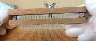
I show two homemade versions of its execution with photographs below.
This design can be easily assembled from planks, giving it the shape of an inverted bench. It is now convenient to make a revolution counter, that is, the number of turns, from an old calculator.
To do this, open its case and carefully solder the wiring to the contacts of the “Equal” button. Their second ends are connected to a reed switch, which is fixed to the stand of the winding machine near the axis of rotation. A small magnet is mounted against it on the rotating part.
Each revolution of the shaft is accompanied by the passage of a magnet next to the reed switch and the operation of the latter. Closing the contact is accompanied by the display of the next number on the display.
The turns of the winding must be laid in even rows, as they did in Soviet times, appreciating the quality of work, and each layer must be covered with insulating paper.
Some home-made workers practice bulk winding, creating a total mass without any additional insulation according to the principle: it works that way.
Indeed: it works, but not for a long time. At numerous bends, knots with additional mechanical forces are created. Dynamic loads from magnetic fluxes and heating of the wire weaken the insulation at these points.
It breaks through over time, creating an interturn short circuit. The transformer loses the necessary performance characteristics and fails.
Thin baking paper produced for the manufacture of culinary products is very suitable for insulating layers.
They simply cut strips out of it with a stationery knife along the width of the coil opening and lay each layer with them.
The thin wire requires very careful handling; it can break from a small accidental tug. If there are few turns wound, then it is better to replace it. But, it is quite acceptable to strip the insulation, twist and solder the twist, and then re-insulate it.
When space inside the coil is limited, the broken end and its continuation are taken outside the frame and a connection is made there. In this case, it makes sense to place it on an individual terminal: it can be used as a separate tap to relieve some of the voltage or for checks.
The power windings of transformers of chargers and welding machines may be subject to increased heating. Therefore, it is useful to enhance their insulation by impregnating liquid glass. This is a regular silicate glue used to glue paper.
However, this technology takes a long time to complete: each layer must be dried after impregnation. But it will work reliably and for a long time. Therefore, this is done only for the most critical devices.
Windings created using the bulk principle can be strengthened by impregnation with a special varnish with electrical insulating properties, for example, grade ML-92. Impregnation is applied periodically during work to several layers of wire and allowed to dry.
You should not use nitro varnish, adhesives, or epoxy putties. They can corrode the factory insulation layer and are not suitable for copper in terms of linear expansion coefficient when heated: additional mechanical loads will be created.
Impregnation of the turns after the final winding of the coil is useless: liquid varnish simply will not penetrate deep into the winding.
How to mount magnetic circuit plates: what to pay special attention to
First, I recommend picking up one plate and examining it. You will notice different color shades on the two opposite sides. This is due to the insulation of iron with varnish. It happens that it is applied only on one side.
The plates must be inserted so that the layers of varnish constantly alternate and do not match in color.
Features of core disassembly
Electrical steel is soft, and in the assembled core it is tightly compressed. Often wedges made of fiberglass are used for fastening, sealing the free space. During disassembly they should be pulled out or knocked out.
Only after this the first plate is removed. If it fits tightly and cannot be reached, then it is first separated with a thin knife blade, and then knocked out with a hammer and a metal flat bar. You can use the blade of a simple screwdriver.
Features of core assembly
The main plates are alternately inserted from below and above the coil until its internal space is completely filled. Then additional inserts are added to them and knocked down on a flat hard object with light blows of a hammer.
It is necessary to ensure a tight fit of all joints to prevent loss of magnetic flux as it flows through the core.
In most dismountable magnetic cores, their structure is tightened with mounting bolts or screws. They must be reliably isolated from the core plates.
For this purpose, it is enough to cut out flat washers from thick cardboard and wrap the screws themselves in strips of paper.
Even such simple insulation will prevent the loss of electricity due to the creation of eddy currents.
All fastening screws should be tightened well. During operation, the transformer housing is exposed to dynamic forces from the magnetic flux flowing through it.
A poorly compressed magnetic circuit will hum, produce increased noise, and transmit additional forces to the winding. This cannot be allowed. The core must be assembled very tightly.
Clarification of a number of technical parameters
However, before starting the practical part, you will need to give clear answers to a number of questions.
- How exactly should the future unit change the current: increase it or decrease it?
- What voltage will be supplied to the primary coil and removed from the secondary?
- What will be the operating frequency of this device?
- How much power should it have after assembly is completed?
Video of transformer rewinding
Time of different stages of this video:
26 min 28 sec
- foil screen between primary and secondary
27 min 52 sec
- how to correctly connect the windings in series
36 min 43 sec
- how to find out the direction of turns using a battery and a multimeter
44 min 14 sec
- calculation and winding of a new secondary winding
1 hour 24 minutes 20 seconds
— mains voltage sag and other losses
1 h 30 min 01 sec
— no-load current
1 hour 32 minutes 14 seconds
- aluminum soldering
1 hour 33 minutes 42 seconds
- result
I recommend reading further only after watching the video. It has a lot more important details.
The benefits of a detailed drawing
After providing comprehensive answers to the above questions, a diagram of the transformer device can be drawn up on paper or on a computer. It is not superfluous to do this even with a clear understanding of all the parameters and features of the radio component.
Often a drawing allows you to significantly clarify
- Scheme of connecting and bringing out contact wires;
- Number of plates in the W-shaped core;
- Method of arrangement of primary and secondary coils.
Winding
I wound four parallel wires at the same time. As a result, I got four windings on each coil in each row. This number of windings makes it possible, by connecting them in series (or parallel), to combine the required voltage (and current).
For a laboratory power supply used as a work tool, this is the most convenient option.
IMPORTANT!
For a transformer with an “O” shaped core, with two coils on the right and left (such as the one discussed in this article), it is best to divide each winding into two (identical) ones, wound on different coils and connected in series. In this case, the efficiency will be higher.
BY THE WAY
when laying on the frame, it is advisable to slightly bend the wire outward before each bend at the corners, so that the turns do not then move away from the frame, forming a gap in which the winding density deteriorates. I additionally pressed down the wire with a pine block after each bend on the frame.
Calculation of wire length.
Before winding, it is necessary to measure the width of the frame and the width of the window between the coil frames (or frame and core). After this, you need to calculate the length of the wire and take into account its diameter (with varnish insulation!). If winding occurs without disassembling the core, by threading the wire through the window, then a piece/pieces of wire of the required length will need to be “bitten off” in advance, so it is important not to make a mistake. If the wire is thin enough (for example, less than 0.5 mm) and long, then it makes sense to make a thin shuttle on which to wind the wire of the required length - this will make it easier to drag it through the window.
Here, for example, the internal length of the frame was 54 mm, and expecting to lay 52 turns of wire with a diameter of 1 mm, I did not guess - I had to partially overlap the last half turn (apparently I did not take into account the thickness of the varnish insulation). See the picture (click to enlarge):
When calculating the capabilities of a window, you need to take into account the total thickness of the insulating pads made of paper or varnished fabric between the windings.
To accurately calculate the required length, you need to make a control turn and measure its length. At the same time, in each next row the turn will be a little longer (the thickness of the bottom row and the thickness of the inter-row insulating spacer will affect). You need to understand that, for example, with 50 turns, a length error of one millimeter per turn will give an error of 5 cm at 50 turns. You also need to take into account the margin for conclusions (I added 10 cm on each side to the total length of the pieces, i.e. only 20 cm - this was enough for both conclusions and a possible error).
Purchase of components and consumables
After the schematic diagram has been fully prepared, you can begin purchasing the parts and consumables needed for assembly.
Usually, the necessary materials and accessories, including varnished wire and terminals, are easy to find in the first radio store you come across.
First you need to buy
- Electrical tape or heat-resistant tape;
- Core configuration corresponding to the project;
- Insulated wires.
Wire diameter
The parameter is determined by the strength and current density, on average 2 A/mm2.
- On the 1st winding: I = P1 / U1.
- Without insulating material: d = 0.8*I^0.5 – the root is calculated from the current indicator.
- Cross section: s = 0.8*d^2 – squared.
If there is no product with the resulting diameter, you can take several thinner ones and connect them in parallel so that the total cross-section is larger than the calculated one.
For a thick wire in the last formula, the coefficient can be 0.65-0.7. To avoid calculating it, you can use the table:
Next, the area with insulating material is determined: s' = 0.8d^2 - but here the characteristic is taken from the table, with insulation.
To obtain the area of the core window, sum up all the area readings obtained and multiply the indicator by 2 or 3.
Assembling the winding machine
When making this electrical device yourself, you will need to wind the wire. Winding a transformer with your own hands is carried out on a simple homemade machine tool. You can do it in a couple of hours.
First you need to take a board measuring 10x40 cm. A couple of bars measuring 50x50 mm should be attached to this base with screws. The distance between them should be at least thirty centimeters.
How to wind?
The core is covered with tape 5 times, the wire is placed in the groove, and winding-1 is wound. Both ends should be brought out to one side and insulated with Teflon tape or cambric. To fix the last turn, you can use regular thread, so it will not unwind.
4-5 circles of tape are laid on top of this, the rod is placed in the body of a syringe 3 cm long. It is also wrapped with tape twice and a secondary winding is performed, the width is one and a half centimeters. Each layer is insulated with tape or double fluoroplastic tape. The ends are brought out on different sides, three conclusions are made from one, and one from the second.
All this is again insulated with adhesive tape in five layers, flexible wires for output are soldered to it, and insulated again.
If a break occurs somewhere, the place is cleaned, twisted, soldered, isolated. Therefore, you can use the old wire, as long as it is properly soldered. To increase electrical strength, each layer of winding is impregnated with acrylic varnish or epoxy.
The turns are placed as close to each other as possible, parallel to the core if possible.
Reel Rods and Handle
Next, miniature holes with a diameter of 8 mm are drilled. Rods are inserted into them onto which the transformer coil will be strung.
- All that remains is to apply a small diameter thread, tighten the washer and mount the handle.
- It is important to note that the dimensions of such a machine can be anything.
- In other words, it can be fully adapted to the intended core size.
- However, if the project involves the use of a ring core, then it will have to be wound entirely by hand.
What power will it have?
Once you can answer each of the questions listed, purchase the required materials. You can easily buy the necessary materials in specialized stores. You will need wires, premium quality tape insulation, and a core.
The transformer itself requires winding. For these purposes, a machine should be created, the manufacture of which is carried out from a board forty centimeters long and ten centimeters wide. Several bars need to be attached to the board using screws.
The distance between the bars should not be less than thirty centimeters. Then you should drill holes eight millimeters in diameter. In the created holes you need to insert special rods for the device’s coil.
A thread should be created on one side. By tightening the equipped washer, you will get its handle. The dimensions of the winding machine can be chosen at your own discretion. First of all, the right choice directly depends on the size of the core. With its ring-shaped form, the winding is created manually.
According to the diagram of the transformer device, the device can be equipped with a varied number of turns. The required quantity is calculated based on power. For example, if it is necessary to create a device up to 220 volts, the power should reach at least 150 watts.
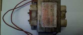
The shape of the magnetic wire should be O-shaped. You can make it out of a used TV. In this case, the cross section is determined using a certain formula.
Effect of power on the number of turns
A transformer made by yourself can be equipped with any number of turns.
The instructions on how to make a transformer indicate that the required number of turns is calculated based on the power of the intended device.
Operating principle of current transformer
Perhaps everyone who has ever worked with analog electronics has encountered interference from a 220V network. It would seem that if these interferences are so difficult to get rid of, then maybe it should be very easy to determine when the load is turned on? However, everything turned out to be not quite so simple.
Indeed, the simplest measuring current transformer can be made from a coil of ordinary two-core power cable - run the measured current along one of the wires, and pick up a useful signal from the other. Let's try to estimate (at least in order of magnitude) what voltage is formed at the ends of the “signal” core if current is passed through the “power” wire to the target load? Maybe this will be enough to solve the problem?
A coil of cable in this configuration is essentially an air-core transformer. The current passing through the turns of the power core forms an alternating magnetic field. This field creates an electromotive force, induced emf, in each turn of the signal wire. The magnitude of the EMF is proportional to the rate of change of the magnetic flux passing through the surface surrounded by the coil:
If we assume that the turns in the cable coil are packed tightly enough, and the current in the measuring core is zero, then the magnetic flux through all turns will be the same, and it can be calculated as the product of the inductance of one turn, the number of turns and the current in the power core. The EMF in all measuring turns will be the same and the total voltage at the ends of the signal core will be equal to the product of the number of turns per EMF in one turn:
In a household AC network, where is the frequency equal to 50 Hz, and is the amplitude value of the current. The value can be determined based on the load power and the effective voltage value equal to 230 V. As a result, for the derivative of the current with respect to time we obtain the following formula:
For example, for a 1 kW load connected to a regular household network with a voltage of 230 V, the amplitude of the current derivative with respect to time calculated using this formula will be slightly less than 2000 amperes per second.
We calculate the inductance of one turn based on the radius of our coil and the radius of the wire from which the cable core is made:
Here is the magnetic constant. For a coil of cable with a diameter of 10 cm, having cores with a diameter of 2 mm, the inductance of the turn is about 0.25 μH. If such a coil is made from a cable 10 meters long, you will get about 30 turns. As a result, for our load of 1 kW, the voltage on the open signal core will be as follows:
The value turns out to be quite detectable, but what happens when the load is turned on or off, when the current can change tens or even hundreds of times faster than during normal operation? In this case, instead of 450 mV, there may be a voltage surge of several tens or even hundreds of volts at the ends of the signal wire, which may well damage the microcontroller input.
To solve the problem with the dependence of the induced emf on the signal frequency, current transformers use a completely different operating mode - instead of opening the secondary winding and measuring the voltage on it, it is short-circuited and the current passing through it is measured.
As soon as current appears in the signal core, it creates its own magnetic field, directed opposite to the original one. In an ideal case, the current in the signal core will instantly increase so much that it completely compensates for the magnetic flux of the power core. For the case considered above with the same number of turns, the current strength in the two wires will be equal, and the induced emf in the signal wire will tend to zero. With a different number of turns, the ratio of currents in the power and signal windings will be determined by the ratio of the number of turns: , and the total magnetic flux and induced emf will also tend to zero.
Computing application for Android
Mathematical expressions that can be found in specialized literature will provide reliable assistance in clarifying a number of parameters. Almost all of these formulas have already been included in computer programs, which in most cases makes it possible to minimize the calculation part.
You just need to specify some data about the future device in the program interface, and the smartphone application will display a comprehensive table with the requested information.
Electrical specifications
To correctly make a model yourself, a number of parameters are determined:
- Output power: P2 = U2*I2, which is obtained by multiplying the output parameters. If there are several secondary coils, they are summed.
- The efficiency does not exceed 80%, so the primary: P1 = P2/0.8 = 1.25*P2.
- The area of the central part is calculated based on P1. For steel, this value is: S = P1^0.5 - calculate the root of the primary power value. For tin, baked wire, roofing iron, S is taken three times more: S = 3*P1^0.5.
- Turns of the first coil: w1 = 50/S.
- Second: w2 = w1*U2.
The w value is increased by 5-10%, because Some voltage is lost due to resistance.
Frame production stage
The frame part is made of cardboard. Those who do not yet have experience in such assembly and therefore do not know how to make a transformer frame with their own hands must take into account that its internal part must have larger dimensions than the core.
If a ring-shaped core is used, there will be two coils. When choosing an W-shaped core configuration, there will be only one coil.
Arrangement of the reel housing
The body is made of high-quality cardboard paper. Its inner side is slightly larger compared to the core part of the core. When using an O-shaped core, several coils will be required. With a w-shaped core, it is enough to use only one coil.
When using a round core, it should be wrapped using insulation. Then you can carry out wire winding. Once you are done with the primary winding, it should be covered with several insulating layers. After this you need to wind the next layer. The ends of the existing windings are brought out to the outside.
When using magnetic wire, the transformer body is assembled step by step:
- A certain size of sleeve with the required cuffs is cut out.
- Cardboard cheeks are created.
- The main part of the coil is rolled up into a special box.
- Cheeks are placed on the sleeves.
Winding wire and applying insulation
If a round core was chosen as the base, then it should first be wrapped with electrical tape. Next you can start winding the wire.
- After the application of the primary winding is completed, it is covered with dense insulation.
- Then it’s time to wrap the second layer.
- The ends of the windings are brought out, and contacts are soldered to them for interfacing with other equipment.
Current transformer design
In the real world, the signal core has a non-zero passive resistance and to create a current in it, a non-zero value of the induced emf is necessary, which means the magnetic flux of the power winding must not be completely compensated. To keep the signal winding current as close to ideal as possible, you need to maximize the ratio of the open winding voltage to the actual voltage drop required to produce that current. This can be achieved in different ways:
- reducing the target voltage drop across the signal winding
- increasing the number of turns of the power winding
- increasing the number of turns of the signal winding
- increasing the inductance of each turn
The voltage on the signal winding can be minimized by using a more sensitive current measurement circuit. In the simplest case, the current is converted to voltage across a shunt resistor and the voltage drop is determined by the range of detected currents and the characteristics of the microcontroller's analog input.
It is difficult to significantly increase the number of turns in the power winding, because the load is connected through it, which means it must have a sufficiently large cross-section and reliable insulation. But in the signal winding, the number of turns can be increased quite significantly, and since the current in the signal winding is inversely proportional to the number of turns in it, the cross-section of the wire can also be significantly reduced. That is why in current transformers the signal winding usually has significantly more turns than the power winding.
The inductance of each turn can be greatly increased using a ferromagnetic magnetic circuit. Ordinary electrical steel increases magnetic induction several thousand times, and also concentrates the magnetic field inside the magnetic circuit, ensuring the complete passage of magnetic flux through the turns of the signal winding. For example, one turn on a ferrite ring R36x23x15 PC40 has an inductance of about 3 μH, which is 12 times greater than the 0.25 μH that we got for a turn in a much larger cable coil.
The presence of a magnetic core in the transformer design also leads to some limitations:
- The field strength inside the core is limited by the magnetic saturation effect, i.e. the greater the current being measured, the larger the cross-section of the core must be in order to distribute the magnetic field over a larger area.
- The core must have time to remagnetize following the change in the magnetic field of the power winding, i.e. the frequency of change of the measured current is limited by the characteristics of the core material.
- When the core is remagnetized, heat is released, which limits the product of the frequency of current change and the magnitude of the magnetic field.
All these restrictions, however, have a greater impact on the design of power transformers, and for an instrument transformer it is quite easy to provide a very large margin for each of these restrictions.
Windings for increasing voltage
The reel is placed on a block of wood. It should already have a hole for the winding rod. The further sequence of actions is as follows.
- A couple of layers of varnished fabric are wound onto the reel.
- The tip of the wire is fixed on the cheek, after which the handle begins to rotate.
- The laying of the coils must be monitored and, if necessary, compacted.
- At the end of the primary winding, the wire is cut and fixed on the cheek.
- The working terminals of the windings are wrapped with electrical tape or covered with heat-shrinkable tubing.
Operating principle
The wire, as well as the coil, must be secured in the winding device, while the base of the device is in the winding device. Calm movements should be carried out without disruption. Lower the wire onto the frame part.
There should be 20 centimeters between the surface and the wire to place your hand on the table to hold the wire. In addition, additional materials must be located on the tabletop surface, without which it is impossible to create a step-up transformer with your own hands.
With your right hand you need to moderately rotate the winding device, and with the other hand you need to hold the wire. It is important to lay the wire evenly. Next, you need to insulate the frame, while the end on the wire should be threaded through the hole in order to be fixed in the area of the axis of the winding device.
The beginning of winding should be carried out slowly, as carefully as possible: it is important to have the skills so that the turns lie as evenly as possible.
It is important that the angle of the wire being installed, as well as the tension, are always constant. You should not wind the layers all the way, since it is possible that the wires will slip and, accordingly, slip into the cheeks on the frame.
- Immersion blender - which company is better to choose for your home? Photo+video reviews
- DIY tester: instructions, diagrams and solutions on how to make a simple homemade device. Step-by-step instructions on how to make a tester from a smartphone
- DIY voltage regulator: master class on how to make a simple voltage regulation device
Set the counter to zero. Glue the insulating element together or press it tightly with a rubber ring. It is important to make all turns a couple of turns narrower than the previous ones.
First start-up and diagnostics
It is likely that when you first start up a new device, it will begin to make a characteristic ringing sound. This means that it is necessary to better secure all fasteners.
Next, a new test of the transformer is carried out. It is connected to the network, after which the voltage on the secondary winding is measured. If it corresponds to the design, albeit with slight deviations, then the new device can be used for its intended purpose.
It is advisable to leave it under voltage for two to three hours after starting. In this case, you need to make sure that it does not heat up excessively.
Superconducting transformer almost with your own hands
Back in 2016, one young but very impressionable fourth-year student at the Faculty of Energy was influenced by an article in which the author very popularly showed what high-temperature superconductors (hereinafter referred to as HTSCs) are today.
Blinded by the desire to revive the rather monotonous and extremely conservative electric power industry in his soul, making his way through a veil of contradictions and an acute lack of finance, the young bachelor, together with his colleagues, nevertheless built a transformer with windings from a high-temperature superconductor. Enjoy reading! Why make transformers superconducting?
The current products of transformer manufacturing have truly achieved, in a sense, an ideal. Large power transformers, the same ones that are located in brick or iron transformer substations (TP-ears) in your yard, as well as larger representatives, have an efficiency of about 99%. A huge number of regulatory documents regulate the operation, diagnostics, method of installation and creation of such transformers, and at conferences and exhibitions more and more representatives appear with an innovative nut in the core of the magnetic circuit or revolutionary oil with a reduced concentration of gases dissolved in it.
A typical representative of power transformers
And, it would seem, where should we ignoramuses go into this area of engineering thought, polished to the smallest detail. Is the extra half a percent of efficiency that superconducting transformer windings can provide worth the expense of organizing a special cryogenic facility, retraining engineers and re-equipping production? Why reinvent the wheel? Primary analysis shows that there is no need. However, let me give one argument, which became the reason why this article subsequently became possible: “What if the bicycle is crash-proof?”
Advantages of a transformer with HTSC windings over a conventional one:
— Almost complete absence of energy losses in the windings (the wires are superconducting, they do not heat up); — Explosion and fire safety (liquid nitrogen, unlike transformer oil, does not emit explosive gases); — Less weight and dimensions (the current density in a superconducting wire can be 10 times higher than that in a copper wire, at the same voltage); — Ability to limit short circuit currents
.
Although the first three advantages are strong, they all pale in comparison to the huge price that has to be paid for superconductivity. Therefore, I’m afraid the commercial success of HTSC transformers can only occur in particularly demanding types of military and space equipment or at facilities with special fire safety levels. However, the fourth property can dramatically change the picture, and personally, it alone seems to me to be sufficient to not only pay attention to the HTSC paradigm, but also to conduct some research. In fact, this is what many of my colleagues around the world have done, take at least the works [1-3]. What's the trick here?
About the physics of current limiting
At the moment, when talking about HTSC wires in the context of the electric power industry, we almost always talk about composite HTSC tapes based on ceramic compounds. As you can see from the image below, the superconductor (YBCO layer) deposited on a metal substrate is covered on all sides with some protective layer. This protective layer can be some metals and their alloys, such as copper. Naturally, these materials do not have superconducting properties at the temperature of liquid nitrogen, which means that if the superconductivity of YBCO ceramics disappears for some reason, then the entire current is parallelized between these layers, in accordance with their resistive resistance.
Any current is proportional to the voltage applied to a given resistance, which means that if suddenly, out of nowhere, resistance appears in the circuit where it was not there before (superconductivity has collapsed), then the current (at a constant voltage) will decrease.
Moreover, the degree of this reduction depends on the resistance of the materials surrounding the HTSC layer. But how to destroy superconductivity? There are actually 2 fundamental ways: raising the temperature above the critical one, at which superconductivity cannot exist, or influencing the HTSC with a magnetic field above the critical one. Moreover, if a current flows through a superconductor, then it also creates a magnetic field that tries to penetrate this superconductor, and if the current creates too much of a field, then the superconductivity begins to gradually
collapse.
The current at which superconductivity begins to break down is usually called critical
.
Let's build a transformer!
That's it! Now, I’m sure you understand enough to start building a transformer, and believe me, for me it was a really exciting journey, because if winding wire for a regular transformer (hello to those who wound it) is a very meticulous and rather tedious task, then for a HTSC transformer the complexity increases significantly. Especially when such a device is assembled from scrap materials. Let's find out why!
Winding frames
One of the serious disadvantages of a HTSC transformer is that the core is not and cannot be superconducting. Therefore, we have two options on what to do: heat and waterproof the core from the windings, increasing the distance between it and the windings and reducing the efficiency, or put the core in nitrogen along with the windings, creating a large boiler for nitrogen, since the no-load losses of the transformer are nowhere to be found children We decided to take the first route, making a cryostat in the form of a hollow cylinder. Why did you choose this as a frame for the secondary winding (which is closer to the core):
Polypropylene pipe and wrapping paper next to it
Pipe with an internal diameter of 100 mm. made of polypropylene is an ideal waterproofing material, but not a very good thermal insulator. Moreover, some types of plastic tend to shrink at low temperatures, which is why the winding wound directly on such a pipe can be deformed along with the pipe. Therefore, it was decided to additionally reinforce this pipe by wrapping it on top with paper impregnated with epoxy resin. There were no problems with paper; you can get plenty of it at the exits of various (large) hardware stores (ala Leroy), where it is free. It's heavier with compound. We had no experience working with homemade paper-based PCBs, and we did not know how a paper-impregnated frame would behave at -196 degrees Celsius. We consulted and decided to take the first ED-20 epoxy resin we came across. When purchasing the resin, we were warned that the hardener (the second component with which the resin is mixed, after which it hardens during a chemical reaction) works in 20 minutes. Why it immediately became clear that it would be impossible to hesitate and the paper would have to be soaked quickly. For this purpose, faithful comrades appeared in the form of a human assembly line.
Improvised conveyor for impregnating paper with epoxy resin
The smell was, frankly, not very good. Also, take care of your hands when working with compounds!
Paper impregnation process
The second frame (for the outer winding) was made in the image and likeness of the first and directly on top of it. To prevent the frames from sticking together, they placed a little random material, which could later be torn off. The result was:
Ready-made frames for windings
To summarize this part, I will say that there is probably simply no cheaper way to create two non-magnetic, non-metallic, cryo-resistant and sufficiently strong frames. The most expensive element in creating the frame was, of course, the compound ~500 rubles/kg, followed by the PP pipe, and then brushes and gloves - this is optional.
Windings
Perhaps the central and most expensive element of this story is the HTSC windings themselves. The reason why the title of this article contains the word “almost” is the price. We purchased 40 meters of HTSC tape, 4 mm wide and 0.1 mm thick, with a critical current of 80 A at a price of 2,500 rubles per meter. Clearly physical. a person is unlikely to pay for something like this. Let's look at their dazzlingly expensive grandeur.
A dazzlingly expensive part of the project described
In addition to the high cost, HTSC tape is also a very fancy material. It does not like severe overheating (over 500 degrees), it has a large maximum bending radius (about 20 mm, if exceeded, the superconductor will begin to deform), and it also cannot be twisted, crushed, or beaten. All this turns working with HTSC wires into a kind of jewelry art. How are we going to wind it?
To be honest, the method chosen for winding the tape on the frame is probably the most primitive. The tape is covered along one side with Kapton tape
, and the edges of the tape protruding beyond the tape are glued together with the tape to the frame. As a result, during the winding process we obtain two factors that hold the winding on the frame: the adhesion of the adhesive tape and the PCB surface and the friction force of the tape on the same surface. In the end, surprisingly, it turned out to be quite reliable.
Kapton tape was not isolated by chance. The fact is that not every material can be reliable insulation at low temperatures. For example, ordinary tape becomes almost glassy and shrinks. The electrical tape also shrinks. Electrical insulating varnishes crack (though not all of them), PVC insulation also shrinks. Kapton (or polyimide) tape behaves extremely calmly at low temperatures (as well as at high temperatures), it is traditionally chosen for HTSC wires when you need to do something “quickly”, although it must be said that it is not cheap compared to ordinary with tape. When you need to do something thorough, they use a coating that is also based on polyimide.
The process of winding the outer (primary) winding
Actually, they wound a transformer with the number of turns 50:25, in practice it turned out a little less, but that’s not the point. The primary winding (outer) was single-start (one spiral along the entire height), the secondary winding (inner) was double-start (two spirals alternate). Which actually gives the critical current for the primary = 80 A and for the secondary 160 A. If we take into account that the mains voltage (for which the transformer was made) = 220 V, then we get about 10 kW of transmitted power with virtually no losses, in a fairly small volume. Winding results:
Primary (left) and secondary (right) windings of a HTSC transformer
Soldering
We have reached the most nerve-wracking process in transformer manufacturing. As mentioned above, a superconductor is not a fan of high temperatures. When we talk about a copper wire capable of carrying 60-80 Amps for a long time without overheating, we mean a cross-section of 16 or 25 mm^2. These are quite massive and unruly wires, which are difficult to give the desired elegant shape for convenient soldering with 4 mm HTSC tape. If you take a sufficiently powerful soldering iron and simple solder, you can overheat the tape. Therefore, it is better to take Indium-Tin solder with a melting point of ~103 degrees. S. Better yet, melt it in a soldering bath, cover the tape and wire with soldering acid and get a fabulous glow of self-adoration from a job well done in the reflection of the hot metal.
Nuance. It is better to solder current contacts, not sparing the area of the tape, for better current input. We took 3 cm of tape along the contact surface with the current contact, but more is possible. We removed the voltage contacts from the current contacts by several centimeters, so as not to measure the voltage drop at the contact point, but directly on the winding. Unfortunately, only a photo of the finale of this action has survived.
Windings with contacts
Cryostat
The final and most artisanal part of our production. The cryostat was made of foam plastic and acrylic sealant. That's all. Unfortunately, not every brand of foam will work. Polystyrene foam with large granules, when exposed to nitrogen, will immediately self-destruct with a crash and roar.
Incorrect foam (left) and correct foam (right)
As for the sealant, jokes aside, we took the cheapest one that was available. I don't know what the trick is here. The main thing is that the sealant is acrylic and not silicone, because the latter (as we were assured at the store) can corrode the foam.
The cryostat was prefabricated; squares with round holes were cut out so that the entire structure would eventually fit inside, while a pipe protruded from the outside of the cryostat, into which the magnetic circuit was supposed to be placed in the future. In other words:
Prefabricated cryostat
As can be seen in the photo, the joints of this entire structure were heavily coated and impregnated with sealant. We benefit from the fact that when the sealant hardens under nitrogen, it feels like very thick cheese to the touch and performs its functions extremely well. At the last stage, a special bottom is cut out under the frame pipe, on which it is installed and, finally, this entire structure is assembled into a single HTSC transformer.
HTS transformer
As a result, we got:
VTSPT-10000, 220/110 V, 50/100 A, OHL
Explanation
HTSC T - the last letter means transformer 10000 - power in VA 220/100 - rated voltages of the primary/secondary windings 50/100 - rated currents of the primary/secondary windings OHL - work under very cold conditions
Experiments
I think every experimenter has tested this mixture at least once the trepidation and ruthlessness with which he subjected his “newly-made beast” to torment. Of course, the HTS transformer was designed to be incinerated. However, we will incinerate it carefully - scientifically.
Here I will show the main experiment for which the transformer was made. Let's short-circuit the secondary winding and, using a switch, supply voltage from the mains (220 V) to the primary winding. Since the resistance of the primary winding and the secondary winding magnetically connected to it (through the air) is small, fairly large currents will flow in the circuits. These currents will exceed the critical level of 80 A and, therefore, destroy superconductivity, due to which the HTSC winding will gradually begin to acquire a finite electrical resistance, which in turn will cause current limitation. Which we will record in the form of a distorted current sinusoid. And the appearance of some final values on the voltage oscillogram (instead of zero in normal mode). The measurements will be carried out using a device unexpected for this experience: a power quality analyzer. It is unexpected because the sampling frequency of this device in oscilloscope mode leaves much to be desired. But what can you do? Nevertheless, let's take a look at the qualitative picture of what is happening.
Current oscillograms (points on the graphs correspond to real recorded data)
The oscillograms on the left (for comparison) show the short circuit mode if the transformer is not filled with liquid nitrogen: we see a slightly distorted but calm sinusoid of the short circuit current, which after a period (half a period is shown in the figure) is turned off by the circuit breaker. On the right is the short circuit mode if the cryostat is pre-filled with liquid nitrogen: we see a strong initial increase in the current, which gradually (starting from 150 A) bends under the influence of increasing resistance. However, due to the higher value of the short-circuit current, the circuit breaker trips already in the first half-cycle.
Unfortunately, for now we are content with only these high-quality results, but soon we will definitely make many more.
Conclusion
Of course, the HTSC transformer leaves behind a lot of contradictions. These contradictions are manifested even in the artisanal method of manufacturing such a complex device. What can we say about real working samples, which you can familiarize yourself with [1,3]. The real HTSC power industry has leapt far ahead with the development of cables and current limiters, undergoing difficulties even in these more developed divisions. It is quite popular to get acquainted with them without leaving this site, for example here.
Nevertheless, no matter how controversial this area of engineering knowledge may be, in the end the one who can justify his rightness will remain right, so we will try.
And in any case, it's terribly interesting!
Thank you for attention! Sincerely yours DOK.
I also express my gratitude to:
Vitaly Sergeevich Vysotsky and the VNIIKP team for their help and advice on this difficult journey. Pavlyuchenko Dmitry Anatolyevich for his enormous support and desire to develop this area from scratch!
Literature
1. Dai S. et al. Development of a 1250-kVA superconducting transformer and its demonstration at the superconducting substation //IEEE Transactions on Applied Superconductivity. – 2016. – T. 26. – No. 1. – pp. 1-7. 2. Manusov V.Z., Aleksandrov N.V. Limitation of short circuit currents using transformers with high-temperature superconducting windings // News of Tomsk Polytechnic University. – 2013. – T. 323. – No. 4. 3. Lapthorn AC et al. HTS transformer: Construction details, test results, and noted failure mechanisms //IEEE Transactions on Power Delivery. – 2011. – T. 26. – No. 1. – pp. 394-399.
A guarantee of durability and reliability
In general, the winding and assembly process does not cause much difficulty. This method can produce devices for a range of applications, including halogen lamps.
In order for the result of all the efforts made to be a unit that is actually suitable for use, the winding technique described above must be carefully followed. This will guarantee not only the serviceability of the transformer, but also its uninterrupted operation for a very long time.
Code for microcontroller
Since in my case it was enough to detect the fact that the load was turned on, the code turned out to be very simple:
int measureCurrent(){ int i; const int cnt = 10; int minv = 1025; int maxv = -1; for(i = 0; i < cnt; i++) { int value = analogRead(A0); if (value > maxv) { maxv = value; } if (value < minv) { minv = value; } delay(2); } return maxv - minv; }
During one oscillation period, the maximum and minimum values on the ADC are measured and the current value is determined by the difference between them. When the pump is turned on, the function returns a value of more than 200 counts, and when it is turned off, it returns less than 10.
Graph of measureCurrent() function values versus time
Conclusion
The result was a fairly simple, reliable and cheap system for detecting submersible pump starts. It has been working continuously for 7 months and has not yet required any intervention.
Making your own current transformer turned out to be quite easy and quite interesting. I have tried to present the experience gained here in as much detail as possible. I hope this article will allow someone to quickly understand the operating principles of a current transformer and implement their own projects using this element.
UPD: The comments suggested a very cheap version of a ready-made current transformer - ZMCT103C, judging by its characteristics it could well be used to solve my problem.
Photo of a homemade transformer
Description and principle of operation
A current transformer is a type of "instrument transformer" that is designed to produce an alternating current in its secondary winding that is proportional to the current measured in its primary. Current transformers reduce high voltage currents to a much lower value and provide a convenient way to safely monitor the actual electrical current flowing in an AC power line using a standard ammeter. The operating principle of a basic current transformer is slightly different from a conventional voltage transformer.
Unlike the voltage or power transformer discussed earlier, the current transformer consists of one or more turns as its primary winding. This primary winding may have either a single flat turn, or a coil of heavy-duty wire wound around a core, or simply a conductor or busbar placed through a central hole, as shown in the figure. You can buy a current transformer in the popular online store Aliexpress:
Because of this type of arrangement, a current transformer is often also called a "series transformer" because the primary winding, which never has more than a few turns, is connected in series with the current-carrying conductor supplying the load.
However, the secondary winding may have a large number of coil turns wound on a multilayer core of low loss magnetic material. This core has a large cross-sectional area so that the magnetic flux density produced is low when using a wire with a smaller cross-sectional area, depending on how much current must be dropped when it tries to output DC, regardless of the connected load.
The secondary winding will supply current either to a short circuit, in the form of an ammeter, or to a resistive load until the voltage induced in the secondary winding is large enough to saturate the core or cause failure due to excessive voltage breakdown.