Various types of transformer equipment are used in electronic and electrical circuits, which are in demand in many areas of economic activity. For example, pulse transformers (hereinafter referred to as IT) are an important element installed in almost all modern power supplies.
Various models of pulse transformers
Design (types) of pulse transformers
Depending on the shape of the core and the placement of coils on it, ITs are produced in the following designs:
- core;
Design of a rod pulse transformer - armored;
Design of an armored pulse transformer - toroidal (has no coils, the wire is wound on an insulated core);
Design of a toroidal pulse transformer - armored rod;
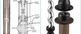
Design features of an armored rod pulse transformer
The figures indicate:
- A - magnetic circuit made of transformer steel grades made using cold or hot metal rolling technology (with the exception of the toroidal core, it is made of ferrite);
- B - coil made of insulating material
- C - wires creating inductive coupling.
Note that electrical steel contains few silicon additives, since it causes power loss from the effect of eddy currents on the magnetic circuit. In toroidal IT, the core can be made from rolled or ferrimagnetic steel.
The plates for the electromagnetic core set are selected in thickness depending on the frequency. As this parameter increases, it is necessary to install thinner plates.
Insulation of wires and windings
IT windings must meet the following basic requirements: be sufficiently electrically strong, the insulation of the windings must withstand without damage long-term exposure to rated operating voltages and short-term exposure to elevated voltages in possible emergency situations.
Reducing the winding capacitance, in turn, is in conflict with the requirement for minimum leakage inductance. However, in most cases, reducing leakage inductance is more important than reducing capacitance.
For these reasons, the dimensions of the insulating gaps are usually reduced to the possible minimum, determined by the required dielectric strength of the windings. They strive to reduce the capacitance by using insulating materials with the lowest possible dielectric constant, as well as due to design factors.
So, the main requirements for insulating materials are low dielectric constant and suitability for conditions with high electric field strength. For high currents and pulse durations, wires of a more economical rectangular cross-section or thin and wide copper busbars made of foil, sometimes made of several layers lined with insulation, are used.
Principle of operation
The main feature of pulse-type transformers (hereinafter referred to as IT) is that they are supplied with unipolar pulses with a constant current component, and therefore the magnetic circuit is in a state of constant magnetization. Below is a schematic diagram of connecting such a device.
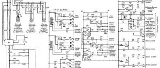
Diagram: connecting a pulse transformer
As you can see, the connection diagram is almost identical to conventional transformers, which cannot be said about the timing diagram.
Timing diagram illustrating the operation of a pulse transformer
The primary winding receives pulse signals having a rectangular shape e(t), the time interval between which is quite short. This causes the inductance to increase during the tu interval, after which it decreases in the (T-tu) interval.
Induction changes occur at a speed that can be expressed in terms of a time constant using the formula: τp=L0/Rн
The coefficient describing the difference in the inductive differential is determined as follows: ∆B=Bmax - Br
- Bmax – level of maximum induction value;
- Br – residual.
The difference in induction is shown more clearly in the figure, which shows the displacement of the operating point in the magnetic conductor circuit of the IT.
Offset graph
As can be seen in the timing diagram, the secondary coil has a voltage level U2 in which reverse surges are present. This is how the energy accumulated in the magnetic circuit manifests itself, which depends on magnetization (parameter iu).
The current pulses passing through the primary coil are trapezoidal in shape, since the load and linear currents (caused by the magnetization of the core) are combined.
The voltage level in the range from 0 to tu remains unchanged, its value et=Um. As for the voltage on the secondary coil, it can be calculated using the formula:
wherein:
- Ψ—flux linkage parameter;
- S is a value that reflects the cross-section of the magnetic core.
Considering that the derivative, which characterizes changes in the current passing through the primary coil, is a constant value, the increase in the induction level in the magnetic circuit occurs linearly. Based on this, it is permissible, instead of the derivative, to enter the difference between the indicators taken over a certain time interval, which allows you to make changes to the formula:
in this case, ∆t will be identified with the parameter tu, which characterizes the duration with which the input voltage pulse occurs.
To calculate the area of the pulse with which the voltage is generated in the secondary winding of the IT, it is necessary to multiply both parts of the previous formula by tu. As a result, we arrive at an expression that allows us to obtain the main IT parameter:
Um x tu=S x W1 x ∆V
Note that the magnitude of the pulse area directly depends on the parameter ∆B.
The second most important quantity characterizing the operation of IT is the induction drop; it is influenced by such parameters as the cross-section and magnetic permeability of the magnetic core, as well as the number of turns on the coil:
Here:
- L0 - induction difference;
- µa is the magnetic permeability of the core;
- W1 - number of turns of the primary winding;
- S is the cross-sectional area of the core;
- lcr - length (perimeter) of the core (magnetic circuit)
- Br is the value of residual induction;
- Bmax – level of maximum induction value.
- Hm — Magnetic field strength (maximum).
Considering that the inductance parameter of the IT completely depends on the magnetic permeability of the core, the calculation must be based on the maximum value of µa, which is shown by the magnetization curve. Accordingly, for the material from which the core is made, the level of the Br parameter, which reflects the residual induction, should be minimal.
Video: detailed description of the operating principle of a pulse transformer https://www.youtube.com/watch?time_continue=13&v=XYxKfYd8Elk
Based on this, a tape made of transformer steel is ideal as an IT core material. You can also use permalloy, which has a minimum squareness coefficient.
Cores made of ferrite alloys are ideal for high-frequency IT, since this material has low dynamic losses. But due to its low inductance, IT has to be made in large sizes.
How to check your device
After the IT is assembled, it is checked. There are plenty of methods on how to check a pulse transformer assembled by yourself or purchased. For testing, circuits are assembled using frequency generators, oscilloscopes, multimeters and other instruments that not only confirm the functionality of the IT.
They test it in various frequency ranges. In a pulse transformer, an open state of the secondary winding is not allowed; this mode belongs to the category of unsafe modes.
How to test a pulse transformer.
They must also have minimal leakage inductance, dynamic capacitance and resistance; be sufficiently strong mechanically.
It must be vibration-resistant and withstand the effects of significant electrodynamic forces that arise both in normal operation and, especially, during short circuits of the load circuit.
The requirements for high electrical strength and minimal leakage inductance are mutually contradictory. Since to increase the electrical strength it is necessary to increase the thickness of the insulation, while to reduce the leakage inductance it is necessary to reduce the thickness.
It will be interesting➡ Oil transformers - what they are, device and principle of operation
Pulse transformer calculation
Let's consider how it is necessary to calculate IT. Note that the efficiency of the device is directly related to the accuracy of calculations. As an example, let's take a conventional converter circuit that uses a toroidal IT.
Converter circuit
First of all, we need to calculate the IT power level, for this we will use the formula: P = 1.3 x Pn.
The pH value displays how much power the load will consume. After this, we calculate the overall power (Rgb), it must be no less than the load power:
Parameters required for calculation:
- Sc – displays the cross-sectional area of the toroidal core;
- S0 is the area of its window (as expected, this and the previous value are shown in the figure);
Basic parameters of the toroidal core
- Vmax is the maximum peak of induction, it depends on what grade of ferromagnetic material is used (the reference value is taken from sources describing the characteristics of ferrite grades);
- f is a parameter characterizing the frequency with which the voltage is converted.
The next stage comes down to determining the number of turns in the primary winding Tr2:
(the result is rounded up)
The UI value is determined by the expression:
UI=U/2-Ue (U is the supply voltage to the converter; Ue is the voltage level supplied to the emitters of transistor elements V1 and V2).
Let's move on to calculating the maximum current passing through the primary winding of the IT:
The parameter η is equal to 0.8, this is the efficiency with which our converter must work.
The diameter of the wire used in the winding is calculated by the formula:
It remains to calculate the output winding of the IT, namely, the number of turns of the wire and its diameter:
If you have problems determining the basic parameters of IT, you can find thematic sites on the Internet that allow you to calculate any pulse transformers online.
Application area
The task of a pulse transformer is to protect an electrical device from short circuits, excessive increases in voltage, and heating of the housing. The stability of the power supplies is ensured by pulse transformers. Similar circuits are used in triode generators and magnetrons. The pulse generator is used when operating an inverter or a gas laser. These devices are installed in circuits as a differentiating transformer.
Electronic equipment is based on the transformer ability of pulse converters. When using a switching power supply, the operation of a color TV, a regular computer monitor, etc. is organized. In addition to providing the consumer with current of the required power and frequency, the transformer stabilizes the voltage value when the equipment is operating.
Video: How does a pulse transformer work?
Varieties
There are different types of pulse circuits of power equipment. The units differ primarily in the shape of their structure. Performance characteristics depend on this. The units are distinguished by the type of winding:
- Toroidal.
The cross-section of the core can be rectangular or round. The labeling must contain information about this fact. The type of windings is also distinguished. The coils are:In the first case, the leakage inductance will be minimal. The presented type of converter is used for autotransformers. The winding is made of foil or awnings made of special material.
The cylindrical winding type is characterized by a low inductance dissipation rate. This is a simple, technologically advanced design.
Conical varieties significantly reduce inductance dissipation. The capacitance of the windings increases slightly. The insulation between the two layers of windings is proportional to the voltage between the primary turns. The thickness of the contours increases from beginning to end.
The presented equipment has different operational characteristics. These include overall power, voltage on the primary and secondary windings, weight and size. When specifying markings, the listed characteristics are taken into account.
Assembling a switching power supply with your own hands: step-by-step instructions and diagrams
Often, radio amateurs have to build a switching power supply with their own hands to power circuits and devices from the network.
Step-by-step instructions will help you understand how switching power supplies work, which are preferable to use, compact, but more complex than conventional transformer ones.
Device
As in a conventional power supply, in a pulsed one the main components are a transformer and a rectifier.
Operating principle of the power supply
The function of the device consists of two actions:
In addition to the mentioned nodes, the pulse power supply also contains the so-called. inverter: a circuit that converts direct current into alternating current with a frequency much higher than the network one - tens of kHz.
Features of work
The reason for the complexity of the circuit is the following: the higher the frequency of the alternating current, the smaller the transformer required and the lower the losses in it. This is why switching power supplies are much smaller than their regular counterparts.
Scheme
The pulse power supply consists of the following functional blocks:
- filter _ Does not allow interference from the network and back (generated by the power supply itself);
- rectifier with smoothing capacitor . A conventional diode bridge produces an almost even (with low ripple coefficient) output constant voltage equal to the effective value of the alternating mudflow voltage - 311 V;
- inverter _ It consists of quickly switching power key transistors and a microcircuit that controls them. The output gives a rectangular alternating current. The conversion process in the inverter is called pulse width modulation (PWM), and the chip is called a PWM controller. In operating mode, feedback is implemented, therefore, depending on the power of the load connected to the power supply, the controller regulates the duration of the opening of the transistors, that is, the width of the pulses. Also, thanks to feedback, input voltage surges and surges caused by switching powerful consumers are compensated. This ensures high quality output voltage;
- pulse high frequency transformer . Lowers the voltage to the required 12 or 24 V;
- rectifier with smoothing capacitor . Converts high-frequency alternating voltage to direct voltage.
AC choke
The main element of a surge protector is a choke. Its resistance (inductive) increases with increasing frequency of the current, therefore high-frequency interference is neutralized, and current with a frequency of 50 Hz passes freely.
The larger the size of the magnetic circuit, the thickness of the wire and the more turns, the more efficient the choke is.
Additional installed capacitors improve filtering by short-circuiting high-frequency interference and diverting it to ground.
Also, capacitive reactances prevent RF interference generated by the power supply from entering the network. A high-frequency transformer differs from a conventional transformer in the material of its magnetic core: ferrites or alsifer are used. The rectifier after the transformer is assembled using Schottky diodes, which are characterized by high performance.
There are two ways to generate high frequency alternating current:
- single-ended circuit . It is used in low-power power supplies - up to 50 W (charging phones, tablets, etc.). The design is simple, but it has a large voltage amplitude on the primary winding of the transformer (protected by resistors and capacitors);
- push-pull circuit . The device is more complex, but it is more economical (higher efficiency). The push-pull circuit is divided into three types: full-wave . The simplest option;
- bipolar . It differs from the previous one in the presence of 2 additional diodes and a smoothing capacitor. The flyback principle of operation is implemented. Such circuits are widely used in power amplifiers. An important feature: the service life of capacitors is extended due to the fact that lower currents flow through them;
- linear _ Used in high-power power supplies (PCs, etc. devices). It is distinguished by the presence of a large inductor that accumulates the energy of PWM pulses (directed to it through two diodes that ensure the same polarity).
2-stroke power supplies differ in the power stage circuit; there are three modifications:
- half-bridge : sensitive to overloads, therefore requiring complex protection;
- pavement : more economical, but difficult to set up;
- push- pull The most economical and therefore in great demand, especially in powerful power supplies. It is distinguished by the presence of a middle terminal on the primary and secondary windings of the transformer. During the period, first one or the other half-winding works, connected by the corresponding key transistor.
Stabilization of the output voltage is achieved in the following ways:
- using an additional winding on the transformer. This is the simplest method, but also the least effective. The voltage removed from it corrects the signal on the primary winding;
- using an optocoupler. This is a more efficient way. The main elements of an optocoupler are an LED and a phototransistor. The circuit is designed so that the current flowing through the LED is proportional to the output voltage. The glow of the diode controls the operation of the phototransistor, which supplies signals to the PWM controller.
Thus, in this technique, the voltage on the secondary winding is directly controlled, and there is no galvanic connection with the key stage generator.
When connected in series with a zener diode optocoupler, the quality of stabilization becomes even higher.
Step-by-step instruction
The manufacturing process of a switching power supply looks like this:
- They calculate the product using an online calculator (published on many websites) or a special program. Depending on the desired characteristics of the power supply, the software will select the parameters of all elements: capacitors, transistors, chokes, etc.;
- purchase all radio components;
- Holes are drilled in the PCB plate in accordance with the diagram and dimensions of the elements. It is not always possible to achieve the desired characteristics the first time, which is why the circuit has to be supplemented with compensators and other elements. It is necessary to leave space for them on the board;
- in the diagram, select the entry points marked with the symbols “AC”, solder the fuse and then, one by one, all the elements according to the diagram;
- perform a check.
It is important to find a suitable scheme and correctly calculate the parameters of the elements.
UPS on a chip
There are many microcircuits with PWM controller function available. Below we discuss several schemes using the most popular ones.
TL494
Since the built-in switches of this microcircuit do not have sufficient power to directly control the inverter’s power transistors (T3 and T4), an intermediate link is introduced from transformer TR1 (control) and transistors T1, T2.
Circuit on a TL494 chip
If you have an old power supply from a computer, the control transformer can be taken from there. The composition of the windings is left unchanged. It is recommended to use MJT13009 bipolar transistors as power ones - the circuit will be more reliable. When using MJE13007 transistors, designed for lower current, the circuit will work, but it will be too sensitive to overloads.
Chokes L5, L6 are also removed from the broken computer power supply. The first one is rewound, since in the original design it is designed for several voltage levels.
About 50 turns of copper wire with a diameter of 1.5 mm are wound around the yellow magnetic core (others will not work) in the form of a ring.
Power transistors T3, T4 and diode D15 get very hot during operation, so they are installed on radiators.
IR2153
Of all the microcircuits, this one is the cheapest, which is why many people prefer to assemble power supplies on it. Here the driver is connected not to the +310 V bus, but through a resistor to the network. With this connection, the power released by the resistor is reduced.
Circuit on IR2153 chip
The scheme provides:
- starting current limitation (soft start or soft start). The component is powered from the network through quenching capacitor C2;
- short circuit and overload protection. Resistance R11 is used as a current sensor. The protection operation current is regulated by trimming resistance R10.
The HL1 LED indicates that the protection has been triggered. The output voltage is up to 70 V, with dual polarity. The number of turns on the primary winding of the pulse transformer is 50, on each of the 4 secondary windings - 23. The choice of the cross-section of wires in the windings and the type of core depends on the desired power.
UC3842
Another inexpensive microcircuit, but very reliable and therefore very popular. When turned on, the current charging capacitor C2 is limited by thermistor R1.
Circuit on UC3842 chip
The resistance of the latter at this moment is 4.7 Ohms, then as it warms up it decreases by an order of magnitude, after which this element from the circuit seems to be “turned off”. Stabilization of the output voltage is due to feedback (loop “secondary winding of transformer T1 – diode VD6 – capacitor C8 – resistor R6 – diode VD5”).
The loop voltage is set by a resistive divider R2 – R3. Chain “R4 – C5” is a timer for the internal pulse generator UC3842. The PWM controller and other microcircuits are installed on plate radiators with an area of at least 5 square meters. cm.
Examination
Check a homemade switching power supply like this:
- connect the leads from the microcircuit to a 40 W lamp;
- connect the device to the network. The lamp will blink faintly;
- use a multimeter to check whether the output voltage matches the desired one;
- check the pulse on the key gates with a multimeter;
- measure the DC voltage on the smoothing capacitors. Normally, it is 1.5 - 2 times higher than the alternating voltage on the diode bridge.
If all values are correct, turn on the power supply with full load.
on this topic
How to make a simple switching power supply with your own hands:
There are many options for switching power supplies. The presented circuits are quite reliable, produce a stable voltage and at the same time are available for manufacturing by an amateur. It is important to remember the dangers of working with electricity and do not hesitate to consult with specialists in doubtful cases.
Advantages
Power supplies with a switching device have many advantages over analog devices. It is for this reason that the vast majority of them are manufactured according to the presented scheme.
Pulse type transformers have the following advantages:
- Light weight.
- Increased level of efficiency.
- Extended voltage range.
- Possibility to build in protection.
Low price.
The structure is lighter due to the increased signal frequency. Capacitors decrease in volume. The scheme for straightening them is the simplest.
Comparing conventional and switching power supplies, it is clear that in the latter, energy losses are reduced. They are observed during transient processes. The efficiency can be 90-98%.
The smaller dimensions of the units reduce production costs. The material consumption of the final product is significantly reduced. The presented devices can be powered from current with different characteristics. Digital technologies, which are used to create small-sized models, make it possible to use special protective blocks in the design. They prevent short circuits and other emergency situations.
The only drawback of pulsed types of devices is the appearance of high-frequency interference. They have to be suppressed using various methods. Therefore, in some types of precision digital instruments such circuits are not used.
Requirements for devices
Converters in power supplies have a number of characteristics. These are functional devices that have a certain overall power. They ensure the correct functioning of the elements in the circuit.
The pulse household transformer has reliability and a high overload threshold. The converter is resistant to mechanical and climatic influences. Therefore, the circuit of a switching power supply for televisions, computers, tablets. characterized by increased electrical stability.
The devices have small overall dimensions. The cost of the presented units depends on the area of application and labor costs for manufacturing. The difference between the presented transformers and other similar devices is their high reliability.
Types of materials
The presented equipment is made from various materials. When creating power supplies of the type presented, you will need to consider all possible options. The following materials are used:
- Electrical steel.
- Permalloy.
- Ferrite.
One of the best options is Alsifer. However, it is almost impossible to find it on the open market. Therefore, if you want to create the equipment yourself, it is not considered as a possible option.
Most often, electrical steel grades 3421-3425, 3405-3408 are used to create the core. Permalloy is known for its magnetically soft characteristics. This is an alloy that consists of nickel and iron. It is doped during processing.
For pulses whose interval is within a nanosecond, ferrite is used. This material has high resistivity.