Home » Lighting » Transformers » How to make a transformer with your own hands?
Step-up or step-down transformers are used today to convert voltage. Their device is a machine that has high efficiency and is used in many fields of technology. Many people often wonder how to make a transformer with their own hands. In order to assemble this device yourself, certain knowledge may be required. You should also know the entire technological process.
Purpose and application
High-voltage transformers (HV) belong to the group of voltage converters. Their purpose is to convert high-voltage voltage into low-voltage to power various devices. According to the principle of operation, voltage converters differ little from power transformers. The secondary winding always has fewer turns than the primary if the converter is a step-down converter, and vice versa if the device is a step-up one.
HV transformers are classified according to:
- number of phases (single- or three-phase);
- number of windings (two, three or four);
- permissible errors;
- installation method (indoor or outdoor);
- purpose (general or special).
Special purpose converters are used in various electrical equipment:
- televisions and radios;
- communication devices;
- household appliances (for example, power supplies for lighting systems).
Most converters of this type are low-power (no more than a few kilovolt-amperes), frequency from 50 Hz, and are intended for indoor installation. The number of windings depends on the equipment in which the transformer will be installed. The insulation is filled with epoxy resin.
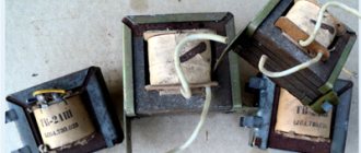
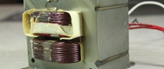
Manufacturing windings for a step-up transformer
The reel must be placed on a wooden block. You should first drill a hole in it for the winding rod. Connecting the current transformer is considered the most critical step. This part should be inserted into the machine and start making the winding:
- Two layers of varnished cloth should be wound on the reel.
- The end of the wire needs to be secured to the cheek and begin to rotate the handle of the machine.
- The coils must be laid tightly.
- After the primary winding, the wire must be cut and secured on the cheek next to the first.
- An insulating tube must be attached to the terminals.
Calculation of electrical parameters
To calculate power, use a formula based on output voltage and current:
Powers are added if there are two (or more) secondary windings.
The efficiency of the converter cannot be higher than 80%, so the primary power is:
The current from the primary winding to the secondary is transmitted through a core, the area of which depends entirely on the power of the primary winding. For a core made of transformer steel, the area is calculated by the formula:
Number of turns of the primary winding:
When using a core made of a different material (some use tin, baked wire, roofing iron), then S must be increased by a third.
Number of turns of secondary windings:
Since part of the voltage is lost due to resistance, it is advisable to increase the calculated amount by 5-10%.
Trial
As soon as the work with winding comes to an end, you should test the created device. For these purposes, the primary winding is connected to the network. To properly check the transformer to identify possible short circuits, it is important to connect the lamp to the current, as well as the winding in series.
The level of insulation reliability is checked by touching the existing wire end of the network winding one by one. If you follow the proposed scheme steadily, then winding the transformer yourself will not present any particular difficulties, and accordingly, even an inexperienced craftsman will be able to cope with such a task.
Selection of magnetic core material
A low-power converter can be made using an armored or rod magnetic core. In armor, rods with a rectangular cross-section are arranged horizontally. This is a relatively complex design and is therefore rarely used. In a core magnetic circuit, the rods are arranged vertically, the windings are cylindrical.
For a step-up transformer, it is better to use an W-shaped ferrite magnetic core. It is important to select the dimensions accurately (the required number of turns must fit on the rod). If the core needs to be disassembled to make another of the resulting plates, the thickness of the package is selected based on the power. The plates are inserted into the coil and tightened using pins and nuts.
Winding insulation
In certain cases, when making a step-up or step-down transformer yourself, insulating spacers should be inserted between the wires. For these purposes, cable or capacitor paper is used.
In the middle, the windings are insulated as tightly as possible. For insulation, as well as to level the surface being constructed, a varnished cloth wrapped in paper on both sides is needed. If there is no varnished fabric, you can solve the problem with folded paper.
To check the operating condition of the device, it is necessary to determine the terminals of the windings.
Core design
To make a step-down converter with two windings with your own hands, you need to find a round ferrite magnetic core.
These are found in old TVs and computer power supplies. In the case of a computer, the central core of the power transformer serves as the rod (it needs to be cut out). Length 2.1 cm, diameter 1.1 cm.
Most often these converters are coated with epoxy resin. In order to disassemble them, heating is required with a hair dryer. The cores are cut out with a grinder (no need to chop). The surface is usually uneven, so the posts are wrapped with tape. If the length is not enough, you can glue the two together with super glue.
Marking
Marking is the first stage, which is carried out if materials and tools are available. Careful research is important to determine the technical specifications.
It is acceptable to do it manually using special tables (but note that in this case you will have to calculate everything yourself using formulas).
You can also select markup using programs - there are some available for free on the Internet. But in this case, a novice radio amateur will not be able to understand the calculation algorithm and learn how to perform the frame independently, without the use of computerized equipment.
How to do it manually
Testing of strength and fastening features is carried out experimentally. A coil is taken, or rather a sample of it, which you wouldn’t mind throwing away, and 10 turns are placed on it, which will be used for the main transformer.
A rod is selected with a diameter four times larger for wires with a thickness of 0.96 millimeters, five times larger if wires up to 1.56 millimeters are taken, and six times thicker if the wire thickness exceeds 2.44 millimeters. This must be taken into account; the selected instructions are available in special technical literature.
Separately, it should be taken into account that in addition to a certain bend, which certainly forms stronger in the first few layers, and then begins to round off, there is also a strong tension and stretching. When marking the frame, take into account that the multiplicity increases several times. For example, for a wire that is 1 millimeter thick, the radius of curvature will be about 5 millimeters. Radii for wires of any diameter are also placed in the corresponding tables.
Class selection
Carrying out markings according to samples allows you to avoid the appearance of loose and uneven surfaces in the winding. Thin getinax is used if it is necessary to increase the rigidity of the frame. For example, if the device power is up to 10 W, then the sizes of small parts will be 0.5, medium - 0.7 to 1.5, and large ones - from 1. Power up to 100 W implies the use of 0.7 - 1, 2, 0 - 4, 1 - 2 mm parts, respectively. For devices with power ratings from 100 to 500 W, take up to 1 to 2 mm for class a, from 3 to 6 for b, from 1.5 to 3 for class c.
For the latter type, with the highest power ratings, it is advisable to increase the radius of curvature by approaching the optimal rounding values. It is better to take special inserts made of material that is used for twisted magnetic wires. They are used if the thickness of the magnetic circuit is twice as thick as the working rod of the device.
Additionally, most of the protruding part of 3 millimeters is installed on the part. This is necessary so that the cheeks of the frame are firmly attached to the equipment. The sleeve is made slightly larger in size than the working rod by 0.5 mm, the gaps should not exceed this figure. Be sure to take into account whether the frame is obtained using hardware or whether it is supplied with the device.
Calculation using programs
There are several dozen programs on the Internet, most of them freely available, that calculate the transformer and its frame. In particular, the CARCASS program is popular, from version 1.0, 2.0 and onwards. It works online, but if you wish, you can download the file and install it on your computer. The program contains information about:
- core type;
- thickness of material and screed;
- core sizes A, B, C, N.
After entering all the information, press the “Enter” or “Calculate” button. The calculation will also appear on the coil line, which can be printed and applied to the available textolite. There is an option designed for a frame with a lock.
Winding instructions
The core must be wrapped with tape (5 layers), a wire with the calculated diameter must be inserted into the groove, and the number of turns calculated for the primary winding must be wound along the entire length. Both ends of the winding are brought out to one side and insulated with vinyl.
The last turn must be secured (simple threads will do) to prevent unwinding.
Next, 4-5 layers of tape are wound, the structure is placed in the body of a disposable syringe 3 cm long. 2 rows of tape and the number of turns calculated for the secondary are wound on the syringe, the width of the winding is approximately 1.5 cm. Each layer must be insulated with tape or two layers of fluoroplastic tape. The ends of the second winding are brought out on both sides. As a result, three outputs are obtained from one end, and one from the other.
The finished structure is insulated with tape (5 layers), flexible wires (leads) are soldered, and another 5 layers of tape are wound.
If the wire breaks during the winding process, the ends must be stripped, twisted, soldered and insulated. The electrical strength is increased by impregnation of each layer of winding with varnish based on acrylic or epoxy resin.
In order to make a transformer with your own hands, it is not necessary to buy a new wire. The old one is also suitable if the segments are connected correctly (twisted and soldered). When winding, the turns should be pressed tightly against each other. It is not advisable to lay them perpendicular to the core (a slight tilt is required). Kinks and folds are not allowed, so a certain amount of tension is required. The insulation tape should be cut into 1.5 cm wide strips to make it easier to cover the wire.
Coil frame manufacturing process
The frame is made of cardboard. Its inside should be slightly larger than the core shaft. If you are using an O-core, then two coils will be needed. If the core is W-shaped, then one coil is needed.
If you are using a round core, then it must first be wrapped with insulation. After this, you can start winding the wire. After the primary winding is completed, it must be covered with 3 layers of insulation. Then you need to start winding its secondary layer. The ends of the windings should be brought out. When using a magnetic core, the frame must be done like this:
- It is necessary to cut out sleeves with cuffs.
- Cut out the cheeks from cardboard.
- The coil body must be rolled into a small box.
- You should put cheekpieces on the cases.
Cutting
Cutting occurs after applying the coil drawing to the material. This is done using a regular construction pencil or even a marker.
The tools needed for cutting vary depending on the thickness of the PCB. For sheets up to 1.5 millimeters, whose cutting is carried out in a cold state, guillotine shears are used. And if the sheets are thicker, then a circular saw is used. Textolite with a thickness of 3 millimeters or more is sawed at a temperature of 80 degrees Celsius with a saw.
How to reduce losses in the magnetic core of a transformer?
In an operating transformer, the core is exposed to an alternating magnetic field. As a result, eddy currents arise around the core. Because of them, the magnetic circuit heats up - that is, part of the useful energy is wasted.
Losses due to magnetization reversal are affected by:
- the nature of the core material. The easier the metal is to magnetize, the easier it is to remagnetize it and the lower the losses in the transformer;
- magnetization reversal frequency;
- maximum value of magnetic induction.
To reduce losses, steel with pronounced magnetic properties is used to produce cores. Such material requires less energy for magnetization reversal.
In monolithic conductors, eddy currents acquire maximum values due to low resistance. Therefore, in order to reduce losses in a transformer, it is necessary to increase the resistance of the core material. Manufacturers of power transformers have found a way out: they assemble a magnetic core from metal sheets. Steel plates for the core are taken no more than 0.5 mm thick.
To truly reduce the eddy current resistance in the core, the metal plates need to be insulated. To achieve this, transformer manufacturers use varnish and scale. The interlayer prevents eddy currents from influencing the magnetic flux in the core. Therefore, losses are reduced.
Manufacturers assemble wafers in two ways:
- end-to-end - in this case the core itself is assembled, then the windings are placed on it and only after that everything is yoke-fastened into a single structure;
- interlacing (laminated cores) - when each next row of plates overlaps the joints on the previous one.
It is easier to install end-to-end magnetic circuits, but the level of losses in them is higher than that of laminated cores. Therefore, laminated transformers are in great demand.
About company
Our organization has a staff of highly qualified employees, many of whom have more than 10 years of experience in the energy sector. In addition, we are the official representative of PJSC METZ named after. IN AND. Kozlov" in the Russian Federation.
The frame is a necessary device inside the transformer, the manufacture of which is subject to special requirements. This device is used to fasten the windings, and depending on the type of vehicle, the features, materials used, markings, etc. change. The frame for the transformer is sometimes made by hand; in fact, this is a difficult procedure.
How to do
Even young electricians can make a toroidal transformer. Winding and calculation are not complicated. We suggest considering how to properly wind a toroidal magnetic circuit for a semi-automatic machine:
- A special machine can be used to wind a transformer on a ferrite core. It will help significantly speed up work and reduce the likelihood of iron jumping off. It can be made as a clamp for wrapping wires;
- It should be noted that the latres that are needed for winding must be the same size. When winding, make sure that there are no gaps between the sheets. If your power transformer has small gaps in the magnetic circuit, then they can be filled with iron sheets from any other transformer, cut to a certain size;
Photo – calculation - After winding of the iron is completed, its terminals are secured by welding. This will prevent the winding from unwinding. Literally two or three weld points are enough;
- After this, the ends of the magnetic circuit are coated with epoxy glue. The edges are first slightly rounded;
- Insulation is wound over the side of the amplifier - it can even be a sheet of cardboard. It can be attached using masking tape. We repeat the action on all surfaces of the magnetic circuit;
- Now you need to wrap textile tape around the cardboard insulation. It is sold in special electrical stores. On top of this layer of insulation you can wrap an additional layer of masking tape;
- Now a wire of the selected cross-section is screwed onto the ring; a special program will help you calculate the size of the wires and the required characteristics. After finishing the winding, everything is covered with NC varnish, one terminal of the winding should remain free;
Photo - winding the winding - Then you need to make insulation from varnished fabric or textile tape, on top of which the second winding is wound. It is also varnished. All that remains is to screw on the last insulation and protect it. Continue actions until the required number of windings is obtained;
Photo - tape wrapping - The secondary winding is wound from a larger wire cross-section. If a network transformer is needed for arc welding, then it is necessary to add a certain number of turns at the end, in addition to the calculated winding ones.
Considering that 1 turn carries 0.84 Volts, the winding circuit of a toroidal transformer is carried out according to the following principle:
| Number of turns on the primary winding | Secondary voltage, V |
| 260 | 30 |
| 271 | 31 |
| 282 | 28,8 |
| 294 | 27,6 |
| 309 | 26 |
| 334 | 24,4 |
| 359 | 22,6 |
| 389 | 20,9 |
| 419 | 19,4 |
| 434 | 18,7 |
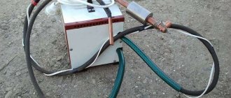
So you can easily make your own 220 to 24 volt toroidal transformer. The described circuit can be connected to both arc welding and semi-automatic welding. The parameters are calculated based on the wire cross-section, number of turns, and ring size. The characteristics of this device allow for stepwise adjustment. Among the advantages of the assembly principle: simplicity and accessibility. Among the disadvantages: heavy weight.
Current transformer
In addition to the standard type of voltage transformers, there is a special type called a current transformer. Its main purpose is to change the current value relative to its input. Another name for this type of device is current.
A current transformer is a measuring device designed to measure the strength of alternating current. Current devices are used when it is necessary to measure high current or to protect semiconductor devices from abnormal values that occur on the line.
The current device is no different in appearance from a voltage transformer; its differences are in the connection and the number of turns in the winding. The primary is made using one or a pair of turns. These turns are passed through a toroidal magnetic circuit, and it is through them that the current is measured. Current devices are made not only of the toroidal type, but can also be made on other types of cores. The main condition is that the wire being measured makes a full turn.
Read also: Is it worth repairing a microwave oven?
With this design, the secondary winding is shunted with a low-resistance resistance. In this case, the voltage on this winding should not be large, since during the passage of the highest currents the core will be in saturation mode.
In some cases, measurements are carried out on several conductors that are passed through the torus. Then the magnitude of the current will be proportional to the strength of the sum of the currents.
Classification of varieties
All types of air transformers come down to two groups:
- Impedance, used to match the voltage drop values at the source and load consumer in order to ensure the most efficient energy transfer;
- Isolators, which are used for safety reasons to isolate a piece of equipment from an energy source.
In air transformers, all currents are considered exciting. They induce a secondary voltage, the value of which is comparable to the total inductance of the electrical system. Therefore, the core base material has the highest magnetic permeability. Such materials also include glass, porcelain, mica, and some types of plastic.
However, only electrical insulating cardboard GOST 2824-86 is distinguished by a favorable combination of strength (electrical and mechanical), density and resistance to changes in environmental humidity.
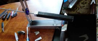
DIY winding machine
One possible option is to make a machine equipped with an adjustable stacker and a thread counter, using the principle of a bicycle wheel.
The wheel is placed on a pin in the wall, and its rim is equipped with a rubber ring. In order to put the core on the rim, you will first need to cut it and then fasten it again, obtaining a solid circle. Having wound the required length of wire around it, one end of it is connected to a core freely located on the rim. The coil moves along the rim in complete circles, as a result of which the wire is laid on the frame. In this case, a bicycle counter is used to count revolutions.
Creating a more advanced device will require the use of stepper motors with positioning of their position. For this, microcontrollers and an electronic counter are used. Such design requires certain skills in radio electronics.