What is a transformer for?
The main property of a transformer is the conversion of voltage or current to the required value and galvanic isolation - this is a very useful property of transformers, which we will discuss below.
And so, for example, in a home electrical outlet the voltage is 220 volts 50 hertz ( AC - this is how alternating voltage is indicated on circuits and power supplies - AC 220v 50hz ), i.e., alternating voltage, and to power a laptop we need 18 volts direct current ( DC - this is the designation for constant voltage DC 18v ). With the help of a transformer, we can convert the voltage to the required value and then rectify it. After which, this voltage will be suitable to power your laptop. Not quite clear? The missing term is Transformation Ratio.
How to calculate transformer windings
What types of transformers are there?
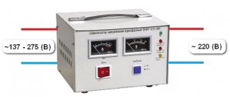
Autotransformer (LATR) is a step-down transformer with one winding, from which, using the rheostat handle, a voltage from 1 to 180 volts is obtained. Such trances are used in laboratory conditions to test various devices. In everyday life it is used in some voltage regulators.
An oil transformer is a monster transformer! with winding pipes filled with mineral oil. These are installed in power substations to reduce the voltage from 10,000 volts to 220. If you transmit a voltage of 220 volts over a long distance through ordinary wires, the losses will be significant. As you know, the higher the voltage, the less effect the wire resistance has. From thermal power plants and state district power plants, a total of 100,000 volts are transmitted via Electric Transmission Lines!
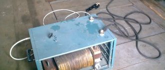
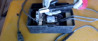
Pulse transformer - not a single modern electrical appliance can do without it, be it a TV, laptop, computer or phone charger. As a rule, it operates at frequencies above 800 Hz in tandem with a PWM controller that increases the pulse frequency as the load increases. An ingenious invention that allows you to obtain large currents from a modest size. Compare the sizes of a traditional welding machine and a welding inverter operating on this principle.
Varieties
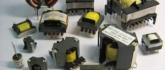
When the need of industrial or household equipment in terms of voltage level is determined, you need to pay attention to the choice of the type of device. The following types are distinguished:
- Toroidal. The core took the shape of a torus. The device is characterized by low weight and small dimensions. Widely used in radio electronics.
- Rod. Used for high or medium power equipment. Simplicity of design distinguishes the core design.
- Armored. They belong to the category of low-power structures. The magnetic drive covers the circuits like armor.
- Multi-winding. Has two or more windings.
- Three-phase. Used in an industrial network. The device is designed to reduce the voltage from 380 V to a level acceptable to the consumer. In some cases it is used for domestic purposes.
- Single phase. Connect to a single-phase network. This is one of the most popular varieties.
The variety of presented designs allows them to be used in various fields of human activity. The cost of equipment depends on the power of the equipment, the complexity of the design, and the scope of application. We have already written about step-down transformers 380/220 on this page.
Video: Power step-down transformer with several secondary windings.
How to distinguish the primary winding from the secondary winding in a transformer
There are three main features of the primary winding of a transformer:
1) In a step-down transformer, the resistance of the primary winding is much higher than the secondary.
2) As a rule, the primary winding is wound with a thinner wire.
4) If the transformer is sealed into the circuit, you can look at the terminals. In the secondary winding, as a rule, a diode bridge is switched on, followed by a high-capacity electrolytic capacitor (from 1000 μF). In the primary, a fuse is usually installed. For details on how to determine where the primary winding is, watch the video below.
How to ring the windings of a transformer?
If you have a gauge or a multimeter at your disposal, finding out where and which winding is not so difficult. We turn on the tester in resistance measurement mode (100 ohms) and ring the transformer terminals. Let's say the tester showed 89 ohms on one of the windings, and only 7 ohms on the other - accordingly, this is a secondary.
How to find out the no-load current of a transformer?
The no-load current is the current that the trans consumes without load; the lower it is, the better the transformer is designed and manufactured. Poor quality of the magnetic circuit, interturn short circuit, incorrect connection increase the no-load current. This current is converted into heat and if it is large (more than 20-100 mA) the trans can burn out. Switch the tester to current measurement mode and connect it in series with the primary winding of the transformer. Based on the measurement results, decide for yourself whether it is dangerous to use such a transformer.
Source
Voltage transformer
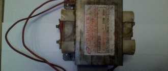
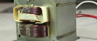
The voltage transformer can be classified more as electrical engineering than electronics. The most common single-phase voltage transformer looks like this.
If we fold back the top protection of the transformer, we can clearly see that it consists of some kind of iron frame, which is assembled from metal plates, as well as two coils that are wound on this iron frame. Here we see two black wires coming out of one coil
and on the other coil there are two red wires
Both of these coils are placed on the transformer core. That is, as a result we get something like this
Nothing complicated, right?
But then comes the most interesting part. If you apply alternating voltage to one of these coils, then alternating voltage also appears in the other coil. But how is this possible? After all, these windings do not touch each other at all and they are isolated from each other. What a miracle! It's all about the so-called electromagnetic induction.
To explain in simple terms, when an alternating voltage is applied to the primary winding, an alternating magnetic field with the same frequency will appear in the core. The second coil picks up this alternating magnetic field and already produces an alternating voltage at its ends.
Transformer windings
These same coils of wire in a transformer are called windings. The windings mainly consist of varnished copper wire. Such a wire is in varnish insulation, therefore, the wire in the winding does not short-circuit with each other. A winding transformer wire looks something like this.
It can be of different diameters. It all depends on what load this or that transformer is designed for.
The simplest single-phase transformer can have two such windings.
The winding to which voltage is applied is called the primary winding. People also call it “primary”. The winding from which the voltage has already been removed is called secondary or “secondary”.
In order to find out where the primary winding is and where the secondary is, just look at the transformer nameplate.
I/P: 220M50Hz (RED-RED) - this tells us that the two red wires are the primary winding of the transformer, to which we supply a mains voltage of 220 Volts. Why do I think this is primary? I/P means InPut, which is translated as “input”.
O/P: 12V 0.4A (BLACK, BLACK) – secondary winding of the transformer with an output voltage of 12 Volts (OutPut). The maximum current that this transformer can supply to the load is 0.4 Ampere or 400 mA.
Magnetic system
The magnetic core is a complex of plates or other elements made of electrical steel, arranged in a selected geometric configuration. The fields of the unit are concentrated in the design. The assembled magnetic core, together with the components and connecting elements, forms the core of the transformer. The part on which the windings are wound is the rod. The area of the system intended to complete the circuit and not carrying any turns of the circuit is called the yoke. The arrangement of the rods in space serves to divide the system into the following types:
- flat design in which all cores are located on a single surface;
- spatial method - longitudinal rods or cores and yokes are in different planes;
- symmetrical order - rods of the same length and shape are arranged so that their spatial arrangement applies equally to all elements and cores;
- an asymmetrical structure involves rods of different types and sizes, located differently from similar parts.
Transformer formula
The main formula of a transformer looks like this.
U2 – voltage on the secondary winding
U1 – voltage on the primary winding
N1 – number of turns of the primary winding
N2 – number of turns of the secondary winding
k – transformation ratio
The transformer also observes the law of conservation of energy, that is, whatever power enters the transformer, such power leaves the transformer:
This formula is valid for an ideal transformer . A real transformer will produce slightly less power at the output than at its input. The efficiency of transformers is very high and sometimes even reaches 98%.
Types of transformers by design
Single-phase transformers
These are transformers that convert single-phase AC voltage of one value into single-phase AC voltage of another value.
Basically single-phase transformers have two windings, primary and secondary . One voltage value is applied to the primary winding, and the voltage we need is removed from the secondary winding. Most often in everyday life you can see so-called network transformers , in which the primary winding is designed for mains voltage, that is, 220 V.
In the diagrams, a single-phase transformer is designated as follows:
The primary winding is on the left, and the secondary winding is on the right.
Sometimes many different voltages are required to power different devices. Why put your own transformer on each device if you can get several voltages at once from one transformer? Therefore, sometimes there are several pairs of secondary windings, and sometimes even some windings are derived directly from the existing secondary windings. Such a transformer is called a transformer with multiple secondary windings. In the diagrams you can see something like this:
Three-phase transformers
These transformers are mainly used in industry and are most often larger in size than simple single-phase transformers. Almost all three-phase transformers are considered power transformers. That is, they are used in circuits where powerful loads need to be powered. This could be CNC machines and other industrial equipment.
In the diagrams, three-phase transformers are designated like this:
The primary windings are designated by capital letters and the secondary windings by small letters.
Here we see three types of winding connections (from left to right)
In 90% of cases, star-star is used.
Purpose
Step-down transformers are used in various fields of human activity. Power structures are installed at substations along the route of power lines. The presented types of devices reduce the current in the network from 380 to 220 V during operation. Household electrical appliances operate at this power. The presented installation is called an industrial current step-down transformer.
Household step-down varieties include devices that operate at lower powers. They accept 220 V to the primary circuit and output 42, 36, 12 V, taking into account consumer requirements.
Types of voltage transformers
A step-down transformer
This is a transformer that lowers the voltage. Let's say we supply 220 Volts to the primary winding and remove 12 Volts. In this case, the transformation coefficient (k) will be greater than 1 .
Step-up transformer
This is a transformer that increases the voltage. Let's say we supply 10 Volts to the primary winding, and remove 110 V from the secondary winding. That is, we increased our voltage 11 times. Step-up transformers have a transformation ratio less than 1 .
Isolation or isolation transformer
Such a transformer is used for electrical safety purposes. Basically, this is a transformer with the same number of windings at the input and output, that is, its voltage on the primary winding will be equal to the voltage on the secondary winding. The neutral terminal of the secondary winding of such a transformer is not grounded. Therefore, if you touch a phase on such a transformer, you will not get an electric shock. You can read about its use in the article about LATR. Isolating transformers have a transformation ratio of 1 .
Matching transformer
Such a transformer is used to match the input and output impedance between circuit stages.
Repair and service
A transformer is a complex piece of equipment. Periodic maintenance and repair will be required. It is recommended to entrust this work to professionals. Only a person with appropriate training has the right to carry out such work.
With an increased heating rate and the presence of noise, it is necessary to rewind the transformer circuits. This procedure can only be performed by an unqualified specialist with a minimum level of knowledge in the field of electrical engineering.
The device has a magnetic drive. It is common to coils. The first circuit is responsible for reducing, and the second circuit is responsible for increasing electricity in the network. Inspection of the transformer is carried out using a certain technology.
Examination
First, a visual inspection of the block is carried out. If overheating is observed during operation, deformations, irregularities, and swelling of the insulation appear on the surface. If the inspection does not reveal any deviations, you need to find the input and output of the device. The first of them is connected to the first coil. This is where a magnetic field appears when electricity is supplied. The output is connected to the secondary winding.
The output signal is filtered. This indicator needs to be measured. The collapsible parts of the housing structure are removed. You need to gain access to the microcircuits. This will allow you to measure the voltage with a multimeter. In this case, you will need to take into account the nominal indicators. If the measurement result is less than 80% of the value specified by the manufacturer, the primary circuit is not functioning correctly.
The first coil is disconnected from the device. It no longer receives electricity. Then the secondary circuit is checked. If there is no filtering, power from the measuring device is used. If there is no normal voltage in the system, the equipment requires repair.
After checking, if the component elements are in good condition, the structure is assembled in the reverse order. If necessary, the unit is repaired.
Operation of a step-down transformer in practice
So, we have a simple single-phase step-down transformer.
It is on it that we will conduct various experiments.
We connect the red primary winding to a 220 Volt network and measure the voltage on the secondary winding of the transformer without load. 13, 21 Volts, although it is written on the transformer that it should produce 12 Volts.
Now we connect the load to the secondary winding and see that the voltage has dropped.
I wonder how much current our incandescent lamp consumes? We insert a multimeter into the open circuit and measure.
Judging by the nameplate, it says that it can supply 400 mA to the load and the voltage will be 12 Volts, but as you can see, with a load close to 400 mA, our voltage dropped to almost 11 Volts. Here's a Chinese transformer for you. It should not be loaded with more than 400 mA. In this case, the voltage will drop even more, and the transformer will heat up like an iron.
How to check a transformer
How to check for short circuit in windings
Although the windings fit very tightly to each other, they are separated by a varnish dielectric, which covers both the primary and secondary windings. If there is a short circuit between the wires somewhere, the transformer will get very hot or make a strong hum during operation. It will also smell like burnt varnish. In this case, it is worth measuring the voltage on the secondary winding and comparing it so that it matches the passport value.
Checking for broken windings
If there is a break, everything is much simpler. To do this, we use a multimeter to check the integrity of the primary and secondary windings. So, the resistance of the primary winding of our transformer is slightly more than 1 KOhm. This means the winding is intact.
We check the secondary winding in the same way.
From this we conclude that our transformer is alive and well.
Similar articles on the topic “transformer”
Source
Advantages and disadvantages of cores
- Stacked ones are more often used for constructing magnetic cores with an arbitrary cross-section, limited only by the width of the plates. Voltage transformation devices with a square cross-section have the best parameters. The disadvantage of this type of core is the need to tightly tighten the plates, the low fill factor of the coil space, as well as increased dissipation of the magnetic field of the device.
- Twisted cores are much easier to assemble than type-type ones. The entire W-type core consists of four parts, while the U-shaped type has only two parts in its design. The technical characteristics of such a transformer are much better than those of a type-setting transformer. The disadvantages include the need for a minimum gap between parts. With physical impact, the plates of the parts can peel off, and in the future it is very difficult to achieve a tight fit.
- Toroidal cores have the shape of a ring, which is made of transformer iron tape. Such cores have the best technical characteristics and almost complete elimination of magnetic field dissipation. The disadvantage is the difficulty of winding, especially wires with a large cross-section.
In W-type transformers, all windings are usually made on the central rod. In a U-shaped device, the secondary winding can be wound on one rod, and the primary winding on another. Especially often, there are design solutions when windings divided in half are wound on both rods, and then connected to each other in series. At the same time, the wire consumption for the transformer is significantly reduced and the technical characteristics of the device are improved.
Step-up and step-down transformer
A huge number of different electronic devices, instruments and equipment are used in everyday life and at work. Quite often, their normal operation requires a step-up and step-down transformer. Each of them works on the basis of self-induction, which allows you to change the current in one direction or another. The name transformer itself means change or transformation. They are mainly used in conjunction with foreign-made electronics designed for currents that differ from domestic standards. In addition, transformers protect electrical equipment and optimize its power supply, making operation as efficient as possible.
Functions and operation of transformers
In electronics, transformers are indispensable devices. However, for them to work most effectively, it is necessary to have a good understanding of what the transformer is stepping down or stepping up. Depending on the needs, they increase or, conversely, decrease the potential in circuits with alternating current.
With the advent of different transformer devices, it became possible to deliver electricity over significant distances. Losses on power line wires are noticeably reduced when the alternating voltage increases and the current decreases. This occurs along the entire length of the conductors connecting the power plant with connected consumers. At each end of such lines, the voltages are reduced to a safe level, facilitating the operation of the equipment used.
Which transformer is called step-up and which is called step-down, and what is the difference between them?
The short answer is that a device that produces a higher potential, compared to the input, is considered a booster. If the reverse process occurs, and the potential at the output is less than at the input, such a device will be a step-down device. In the first case, the secondary winding has a larger number of turns than the primary, and in the second, on the contrary, a secondary winding with fewer turns is used. This is how they differ radically from each other.
Can a step-down transformer be used as a step-up transformer?
Yes, you can. Since to change the functions it is enough to change the connection diagram of the windings with the potential source and the load. Accordingly, the functionality of the step-down transformer will change.
In practice, in order to improve the efficiency of the device, the inductance of all windings is calculated for the exact operating values of current and voltage. These indicators must be maintained in their original state when the step-up and step-down transformer change their functions to the opposite.
How to determine which winding belongs to one or another
Structurally, transformers are made according to such a principle that it is impossible to immediately determine their differences, that is, which wires are called and actually are the primary, and which of them are the secondary winding. Therefore, to avoid confusion, markings are used. The symbol “H” is provided for the high-voltage winding; in step-down devices it serves as the primary winding, and in step-up devices it serves as the secondary winding. Low voltage windings are marked with an “X”.
In order to understand the features, differences and operating principle of each of these devices, they should be considered in more detail.
Operation
To understand what voltage-increasing transformers are, you need to understand the principle of operation. The equipment is manufactured for power plants whose design schemes belong to the pass-through category.
A step-up transformer at power plants is used to provide populated areas and other objects with current with certain technical indicators. Without a converter, the high voltage gradually decreases along its path. The end consumer would receive insufficient electricity. At the final power plant in the circuit, thanks to this installation, electricity of the appropriate value is received. The consumer receives a network voltage of up to 220 V. Industrial networks are provided with up to 380 V.
A diagram showing the operation of a transformer in a line includes several elements. The generator at the power plant produces 12 kV electricity. It is supplied through wires to step-up substations. A transformer apparatus is installed here, designed to increase the indicator in the line to 400 kV.
From the substation, electricity enters the high-voltage line. Next, the energy enters the step-down substation. Here it drops to 12 kV.
Transformers with a reverse operating principle direct the current to the low-voltage transmission line. At the end, another step-down unit is installed. From it, electricity with an indicator of 220 V is supplied to houses, apartments, etc.
General structure and operation of step-down transformers
Transformers convert a higher input voltage into a lower output voltage characteristic, that is, they allow large currents to be reduced to the required values. If necessary, such a device can be used as a booster.
The operating principle of these devices is determined by the law of electromagnetic induction. The standard design consists of two windings and a core. The primary winding is connected to the power source, after which a magnetic field is generated around the core. Under its influence, an electric current with certain specified voltage parameters appears in the secondary winding.
The output power is determined by the quantitative ratio of turns in each coil. By changing this indicator, you can control the characteristics of the output voltage and obtain the required current for household and industrial equipment.
It is impossible to change the frequency of electric current using transformers alone. For this purpose, the design of the step-down apparatus is supplemented with a rectifier that changes the frequency of the current in the range of required values. Modern devices are complemented by semiconductors and integrated circuits with capacitors, resistors, microcircuits and other components. The result is a device with small dimensions and weight, but a fairly high level of efficiency, working to reduce voltage.
Such transformers operate very quietly and are not subject to strong heating. The output current power can be set by adjustments and differs in each case. All new type devices are equipped with short circuit protection.
The step-down transformer has a simple and reliable circuit; it is widely used at substations between sections of power lines. They reduce the mains current from 380 to 220 volts. Such devices are industrial. Those used in everyday life are characterized by lower power. Taking 220 V on the primary winding of the input, they then produce a reduced voltage from 12 to 42 volts in accordance with the connected consumers. The transformation ratio of step-down devices is always below unity. In order to determine it, you need to know the ratio between the number of turns in the primary and secondary windings.
Website for electricians
Question 1. What does a transformer consist of? Answer.
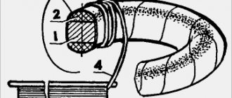
The simplest transformer consists of a closed magnetic circuit and two windings in the form of cylindrical coils. One of the windings is connected to a source of alternating sinusoidal current with voltage u1 and is called the primary winding. The load of the transformer is connected to the other winding. This winding is called the secondary winding. Question 2. How is energy transferred from one winding to another? Answer. The transfer of energy from one winding to another is carried out by electromagnetic induction. An alternating sinusoidal current i1 flowing through the primary winding of the transformer excites an alternating magnetic flux Fs in the magnetic circuit, which penetrates the turns of both windings and induces an emf in them with amplitudes proportional to the numbers of turns w1 and w2. When a load is connected to the secondary winding, an alternating sinusoidal current i2 arises in it under the influence of emf e2 and a certain voltage u2 is established. There is no electrical connection between the primary and secondary windings of the transformer and energy is transferred to the secondary winding through a magnetic field excited in the core.
Question 3. What is the secondary winding of the transformer in relation to the load? Answer. In relation to the load, the secondary winding of the transformer is a source of electrical energy with emf e2. Neglecting losses in the transformer windings, we can assume that the supply voltage U1 ≈ E1, and the load voltage U2 ≈ E2.
Question 4. What is the transformation ratio? Answer. Since the EMF of the windings is proportional to the number of turns, the ratio of the supply voltage of the transformer and the load is also determined by the ratio of the number of turns of the windings, i.e. U1/U2 ≈ E1/E2 ≈ w1/w2 = k. The value k is called the transformation ratio.
Question 5. Which transformer is called a step-down transformer? Answer. If the number of turns of the secondary winding is less than the number of turns of the primary winding, w2 1 and the voltage in the load will be less than the voltage at the transformer input. Such a transformer is called a step-down transformer.
Question 6. Which transformer is called a step-up transformer? Answer. If the number of turns of the secondary winding is greater than the number of turns of the primary winding w2 > w1, then k 2 and Si are the cross-section of the core and the total cross-section w1 of the winding turns. Consequently, increasing the supply frequency f makes it possible to proportionally reduce the cross-section of the core at the same transformer power, i.e. square its linear dimensions l.
Question 13. What is the transformer magnetic circuit used for? Answer. The magnetic core of the transformer serves to increase the mutual induction of the windings and, in general, is not a necessary design element. When operating at high frequencies, when losses in a ferromagnet become unacceptably large, and also when it is necessary to obtain linear characteristics, transformers without a core, the so-called, are used. air transformers. However, in the vast majority of cases, the magnetic core is one of the three main elements of the transformer. By design, magnetic cores of transformers are divided into core and armored.
Question 14. What conditions must the design of the transformer windings satisfy? Answer. The design of transformer windings must satisfy the conditions of high electrical and mechanical strength, as well as heat resistance. In addition, their manufacturing technology should be as simple as possible, and losses in the windings should be minimal.
Question 15. What are the transformer windings made of? Answer. The windings are made of copper or aluminum wire. The current density in the copper windings of oil transformers is in the range of 2...4.5 A/mm 2, and in dry transformers 1.2...3.0 A/mm 2. The upper limits apply to larger transformers. In aluminum windings, the current density is 40...45% less. The winding wires can be of a round cross-section with an area of 0.02...10 mm 2 or a rectangular cross-section with an area of 6...60 mm 2. In many cases, winding coils are wound from several parallel conductors. The winding wires are covered with enamel and cotton or silk insulation. Dry-type transformers use wires with heat-resistant fiberglass insulation.
Question 16. How are transformer windings divided according to the method of arrangement on the rods? Answer. According to the method of arrangement on the rods, the windings are divided into concentric and alternating. Concentric windings are made in the form of cylinders, the geometric axes of which coincide with the axis of the rods. The low voltage winding is usually located closer to the rod, because this allows you to reduce the insulating gap between the winding and the rod. In alternating windings, the HV and LV coils are alternately positioned along the height of the rod. This design allows increasing the electromagnetic coupling between the windings, but significantly complicates the insulation and winding manufacturing technology, therefore alternating windings are not used in power transformers.
Question 17. How is the transformer windings insulated? Answer. One of the most important design elements of transformer windings is insulation. There are main and longitudinal insulation. The main thing is the insulation of the winding from the rod, tank and other windings. It is made in the form of insulating gaps, electrical insulating frames and washers. At low powers and low voltages, the main insulation function is performed by a frame made of plastic or electrical cardboard, on which the windings are wound, as well as several layers of varnished cloth or cardboard that insulate one winding from the other. Longitudinal insulation is called insulation between different points of one winding, i.e. between turns, layers and coils. Turn-to-turn insulation is provided by the winding wire's own insulation. For interlayer insulation, several layers of cable paper are used, and the inter-coil insulation is carried out either by insulating gaps, or by a frame or insulating washers. The insulation design becomes more complicated as the voltage of the HV winding increases, and for transformers operating at voltages of 200...500 kV, the cost of insulation reaches 25% of the cost of the transformer.
Literature: Usoltsev Alexander Anatolyevich. Electric cars. Tutorial. 2013