Home / Accessories and parts
Back
Reading time: 4 min
0
1266
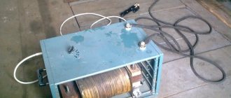
A welding machine is necessary if you need to firmly connect metal elements. It is worth noting that such a welder can both weld and cut steel parts.
The most interesting thing is that the composition and density of elements for such a device is not important. There are many models of cooking units. Pay attention to inverter, transformer and, of course, semi-automatic machines.
Many welding specialists plan to open their own business or earn extra money in their free time. However, the price of a welding machine is prohibitive for the average working person.
- Introduction
- Basics
- Peculiarities
- Static electromagnetic device with alternating current
- Wires in the winding
- Core
- Winding
- D.C
- Let's summarize
Introduction
The price of high-quality units is measured in conventional units, the number of which starts from 100. Not every budget can handle such a purchase.
In such a situation, there is a way out - to make the unit yourself. And when knowledge is lacking, we advise you to start with the simplest thing - by assembling a transformer.
A transformer is a static electromagnetic device, the main organ of a welding machine, literally its heart. Many people ask the following questions:
- How to wind such a transformer?
- How to calculate it?
- How to assemble a welding unit?
Don't panic. In this article we will answer the question of how to make a static electromagnetic device for a welding machine on your own to obtain a high-quality basis for installing the welding unit.
Semi-automatic cooling system
To avoid having to change elements of welding equipment during operation, it is necessary to think through the cooling system in advance. During intensive operation, the components of the unit will overheat.
The simplest option for implementing a cooling system is to install fans. These components are fixed to the sides of the equipment body. For efficient operation, fans are installed opposite the transformer, and the devices are fixed so that they work for exhaust.
Fans from a home computer unit can be used for cooling.
High-quality cooling includes the removal of warm air flow and the supply of fresh air from outside. Holes are drilled into the equipment body using a drill; their number can vary from 20 to 50. As for the diameter of the holes, it should be at least 0.5 cm. It is also not recommended to make holes that are too large to prevent dirt from getting inside the unit .
Petr Sayuk showed the work of a homemade semi-automatic welding machine.
Basics
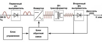
As mentioned above, the transformer is the main organ. The principle of operation is to change the incoming voltage into AC/DC current required for welding work.
A static electromagnetic device is mainly two windings connected inductively.
The first set of turns of wire, to which the energy of the converted alternating current is supplied, and the second windings are located at the “heart”. The latter is made from dynamite steel and serves as a shunt.
You can create a transformer both for personal use and a powerful industrial unit. Let us note that in all cases he is obliged to serve your interests, therefore, to have certain parameters for carrying out welding work.
More common is the assembly of a welding unit with winding a transformer, calculated from an amperage of 150 - 170 and the ability to conduct a voltage of approximately 50 V.
These characteristics are quite sufficient for everyday use. You can weld most metals using electrodes up to three millimeters in diameter. Of course, you can take a diameter of 4 millimeters, but in this case you will lose the quality of the seam.
Therefore, the larger the diameter of the rod of electrically conductive material you have to use, the more power the transformer must have.
The dependence is directly proportional. When assembling a static electromagnetic device, be sure to take note of its extreme outline.
The size of the static electromagnetic device will increase with the planned increase in the power of the welding unit.
At the same time, an increase in weight and parameters is inevitable. We recommend that you take a look at the characteristics that your future device should have - this will help optimize its weight and parameters.
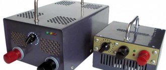
Semi-automatic welding from an inverter
To convert an inverter into a semi-automatic welding machine, you will need three main modules. Electric, providing current from the inverter and welding mode, a mechanism for supplying wire and a torch with a nozzle. The burner creates a gaseous environment in the form of a cloud of protective inert gas that prevents oxidation of the molten metal. For this, a carbon dioxide cylinder is used, which is connected to the device using a hose and an inlet fitting. If you use filler material with a special coating that forms a protective environment, you can do without a cylinder. This method is common among craftsmen.
Figure 2 - Semi-automatic inverter
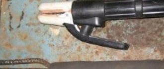
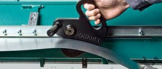
The torch replaces the electrode holder familiar to welders. Externally, it looks like a pistol grip with a key that provides wire feeding.
It moves along a thin channel passing inside the rubberized sleeve connecting the semiautomatic device to the burner. The channel for supplying gas during welding is located in the same sleeve and ends with a nozzle at the end of the torch.
For high-quality welding, a semi-automatic inverter must maintain a constant voltage at the output, like factory equipment.
Required tools and materials
To create a semi-automatic machine from an inverter with your own hands, you will need to prepare the necessary components and equipment.
List of tools and materials:
- Inverter with output current from 150 A.
- A wire feed mechanism that moves it without jerking or slowing down.
- Gas burner for melting the bath.
- A supply hose that will serve as a guide sleeve for the wire moving towards the work area.
- A gas hose that supplies protective carbon dioxide to the welding site.
- Spool of filler wire.
- Electronics unit for controlling the operation of a semi-automatic welding machine. Here the current strength, voltage and operating speed are adjusted.
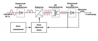
- Semi-automatic welding circuit diagram.
Figure 3 - Diagram of a semi-automatic welding machine
Most of the components are used without significant changes. The wire feed mechanism will require modifications so that the process matches the melting speed. The device must be adjustable, because the speed varies depending on the type of materials being welded, the type and diameter of the wire.
Inverter conversion process
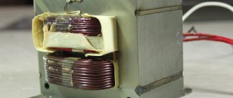
In a finished inverter, you first need to remake the transformer included in it. It is covered with an additional layer consisting of copper strip and thermal paper.
Ordinary copper wire cannot be used for a welding transformer. When welding, it overheats greatly and can stop the operation of the entire semi-automatic welding machine.
The secondary winding of the transformer will also require intervention. It is covered in three layers of tin, insulated with fluoroplastic tape. The ends of the applied winding are soldered. As a result of manipulation, the conductivity increases significantly.
An important element is a fan that will cool the device, protecting it from overheating.
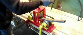
Figure 4 - Inverter winding
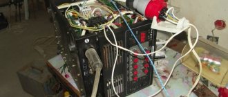
An inverter for manual welding can easily be converted into a power source for a semi-automatic machine. A functioning device does not need to be disassembled, but all additional equipment is placed in a separate housing. It houses a freely rotating spool of welding wire and a pulling mechanism. The side panel displays a wire speed regulator and a socket for connecting a hose.
An old computer system case will do just fine. It turns out compact and neat.
The current parameters can be adjusted on the inverter, then the “positive” terminal is connected to the workpiece from it.
The “negative” contact is removed from the inverter and goes into the new housing. Here it is connected to the sleeve terminal. It is important that the welding wire is connected to this potential.
The gas hose running from the cylinder to the burner is also attached to the housing. If you use the valve from a car windshield wiper, the gas supply will be adjusted.
The above arrangement is simple to implement, and the inverter can be simultaneously used for manual arc welding and as a power source for a home-made semi-automatic machine.
Wire feeder assembly
The feed mechanism is necessary for the uniform flow of electrode wire at the required speed into the welding zone.
Consumables are selected based on the type of metal and the purpose of welding work. Material and size may vary. Therefore, the device must be adjustable to suit different types of wire and welding conditions. Running wire diameters: 0.8; 1; 1.2 and 1.6 mm.
The wire drawing mechanism is purchased ready-made in the electrical goods department or made from improvised materials. For assembly you will need a motor from car windshield wipers, three bearings, a pressure spring and a roller mounted on the electric motor shaft. And also plates at least 1 cm thick of a suitable size on which the bearings are mounted.
Figure 5 — Diagram of the electric motor speed controller
The components are placed on a textolite plate with a thickness of at least 5 mm. The wire is inserted between the bearing and the roller. The exit location should coincide with the fastening of the end of the supply hose into which it is pulled. The wire is wound evenly and carefully onto the reel, because the quality of the future connecting seam depends on this. The coil is installed on a homemade support and fixed. During operation, the wire will unwind and flow to the joint to be welded. With the help of the feeding mechanism, it is possible to simplify and speed up welding work and make it more productive.
Figure 6 — Feeding mechanism
Burner assembly design
A welding torch is a welder’s working tool for making a weld in a protective gas environment.
It lasts no more than six months and is considered a consumable item. The burners operate on the same principle, although they differ in size, materials, maximum temperature, power and gas supply mechanism.
Structural elements:
- base with handle;
- nozzle;
- holder;
- tip;
- insulating sleeve.
Figure 7 — Burner assembly design
Welding is accompanied by overheating of the torch elements. The nozzle and current carrying tip suffer the most. The duration of operation will depend on the material of the tip. Copper is widely used, and in more expensive versions, tungsten. The average tip life is 200 hours. They are made quick-change because they have to be changed frequently.
The handle is made of heat-resistant insulating material, which reliably protects the welder from electric shock. On the torch handle, a button controls the on and off supply of consumables and protective gas. A feeding sleeve with a standard length of 2.5–7 m extends from the handle. The choice of sleeve length depends on the type of work performed.
It is not recommended to allow excess sleeves folded into rings. The output coil voltage causes them to become very hot, which can cause a short circuit.
Figure 8 — Gas burner design
There is a wide selection of gas burners on the market. The models are characterized by the following parameters:
- load current;
- cooling method: air or water;
- the length of the sleeve;
- connection with a plug or Euro connector;
- control method: universal, push-button or valve.
The burner should be compact and lightweight. For a homemade device, a plug connector is sufficient. The plastic case must be durable and ergonomic. The burner is selected according to current parameters that are lower than those of a semiautomatic device.
To ignite the arc, it is necessary that the wire extends beyond the edge of the burner by 10–15 cm.
The supply of consumables is turned on by pressing a button on the torch, which is in the hands of the welder. The toggle switch on the body opens and closes the gas supply to the welding zone.
Control and Power
The semi-automatic device is controlled by a microcontroller.
It is also responsible for converting and stabilizing current. The power supply to the wire pulling mechanism and the valve that turns off the gas is supplied with a voltage of 12 V. To do this, you will need to install a small transformer with a rectifier. Switching between the motor and the valve occurs through a 12 V intermediate auto relay.
Assembly of the unit
The assembly instructions will help you make a quality semi-automatic welding machine. The work is carried out in the following sequence:
- Connect the inverter to power and control devices.
- Thread the wire into the feed mechanism and check for smooth movement.
- Set the required wire feed speed.
- Connect the burner to a hose, which is connected to the feeder.
- Connect a gas cylinder with a reducer and a pressure gauge to the burner.
- Turn on the inverter and feeder.
- Check the flow of gas and wire. After gas supply, the delay in wire movement should be 1–2 s. It enters a ready-made protective environment, otherwise it will stick.
When preparing a home-made semi-automatic machine for the first start-up, you need to take care of cooling the assembled semi-automatic welding machine so that it does not overheat. For this purpose, input and output rectifiers and power switches are mounted on radiators. On the inverter body where the radiator is located, that is, in the most heated zone, it is recommended to install a temperature sensor that will de-energize the device if it overheats.
After this, connect the power part to the control unit, and then turn on the semi-automatic device to the power supply. When the mains lights come on, the inverter needs to be tested. At the output of the device, a current is measured, which should not exceed 120 A. If its value is less, this means that a voltage below 100 V is supplied to the equipment through the wires. In this case, the current is changed and the voltage is controlled, achieving the desired parameters. In this case, the inverter should not overheat.
Under load, the semi-automatic device is checked as follows. The welding wires are connected to a rheostat designed for a current of 60 A and a resistance of at least 0.5 Ohm. The current supplied to the burner is controlled with an ammeter. If the current strength differs from the norm, change the resistance value.
After turning on the assembled semi-automatic device, the indicator should show a current strength of 120 A. This figure confirms the correctness of the work. If eights are displayed, then the reason is insufficient voltage in the supply wires. Welding inverters operate in the operating current adjustment range of 20–160 A.
Control during work
The performance and service life of the semi-automatic device depends on compliance with the temperature regime. The normal temperature on radiators is 75 °C. When overheating, breakdown or short circuit occurs, a sound signal appears. The electronic control unit will automatically reduce the operating current to 20 A, the sound signal will remain until the situation stabilizes. An error in the system is accompanied by the Err code on the indicator.
Peculiarities
The appearance of a welding machine consisting of a self-assembled transformer will not correspond to the production sample, please understand this feature.
It is impossible to make a factory unit yourself from scrap materials. If the exterior is important, of course, you can do it yourself, but it won’t be cheaper. It's easier to buy.
The next feature that should be taken into account is the constant change of characteristics. Even installing them manually does not help.
Let me explain, by setting, for example, the amperage to 120, the unit on a homemade transformer will produce a value less or more each time. This deviation will happen all the time.
Of course, it is not critical, but if your work requires scrupulousness, we recommend considering the option of purchasing a ready-made device.
Idling
The design and purpose of the welding transformer was described above. Now it’s time to talk about the functioning of the unit, such as idling.
During the formation of the seam, the secondary winding is closed between the metal part and the electrode. Under the influence of electricity, the metal melts, as a result of which the parts of the workpiece are reliably connected to each other. After completion of work, the secondary circuit opens. Welding is completed and the machine goes into idle mode.
The electromotive force first appears due to the magnetic field. The emf is then maintained by dissipation.
The electromotive force is closed between the turns of the coil in the air space and forms the no-load voltage indicators. Idle speed is limited to 48 V and is considered safe for the life of the worker. However, in some device models this value can be increased to 70 V.
If the idle speed parameters exceed the set values, then an automatic limitation is used, which is triggered immediately after the end of welding from the transformer. In addition, the device body must be grounded. Such a simple moment will increase the safety of the master’s work.
Static electromagnetic device with alternating current
A self-assembled static electromagnetic device with alternating current for a welder is a classic among types of transformers.
Of course, one of the main advantages of this type of static electromagnetic device, in comparison with those operating on direct current, is cheap assembly and ease of repair.
Although there are several disadvantages to note. And the first, one might call it, was the problematic arc ignition. The combustion is stable and requires a great deal of experience from the craftsman, or the result will not please you; the seam comes out of low quality and with many defects.
However, to build a DC transformer, you will need to first build a static AC electromagnetic device, so the latter is the basis for the former. Everything is quite simple.
Calculation of parameters
To calculate the parameters of the welding machine, data such as the cross-sectional area of the magnetic core, the area of the “window”, the voltage of the primary winding - input and secondary - output, rated power and current density are taken.
Standard parameters:
Calculation of welding transformer parameters
- input voltage - 220 V;
- output - 80 V;
- rated current - 180 A;
- magnetic circuit cross-section - 45 cm²;
- “window” - 100 cm².
The planned power is calculated using the formula: P = 1.5*45*100 , where 1.5 is the coefficient for a U-shaped core. The total output power is 6.75 kW.
Next, based on the ratio of the coefficient 50 to the cross-sectional area, we determine the number of turns per 1 V.
After this, using the formula Imax = P/U, we obtain the maximum force of the electric charge on the primary braid.
Next, using the formula W = U/K, where K is the number of turns, the total number for the primary and secondary windings is determined. If a design is made with stepwise adjustment of the output power, then the number of turns for each stage is calculated, for example, at 90, 120, 160 and 180 A.
Lastly, the wire cross-section is calculated. To do this, the maximum electrical charge of each winding is divided by the current density.
Wires in the winding
As already mentioned, in order to assemble a transformer, at the initial stage you need wires for the first winding and the second winding itself. Remember, in addition to the winding, you need a “core”.
To create it, they use exclusively electrical steel, and then wind wires around it - creating a winding.
Let's start with calculations and the necessary technical characteristics of the future transformer. For example, let’s take the following input data: Voltage – 60V, Current – 120-160A. Based on these characteristics, it is necessary to use wires with a cross section of 4 sq. mm.
We recommend taking wires with a cross-section of 7 sq mm; we consider this option to be more suitable, since your future unit will be less sensitive to voltage drops in the network.
In this case, wires with a copper core with a cross-section of exactly 3 sq mm will be optimal for the primary winding.
It is important to pay attention to the coating when choosing wires. A prerequisite is that it must be made of fabric. And no polymers. Due to the fact that the latter are susceptible to melting from high heat and short circuits.
In a situation where there is no required wire diameter, we recommend taking two thin ones and winding them together.
It is worth noting that this method will increase the total number of turns of the wire in size; accordingly, the transformer housing will have a larger maximum outline. All information posted above concerns the primary winding.
Housing assembly
At the next stage, you can begin assembling the installation body. To do this, you can use iron, the thickness of which is 1.5 mm; the corners must be connected by welding. It is recommended to use stainless steel as the base of the mechanism.
The role of the motor can be the model that is used in the windshield wiper of a VAZ-2101 car. It is necessary to get rid of the limit switch, which works to return to the extreme position. The bobbin holder uses a spring to obtain braking force; for this, you can use absolutely any one that is available. The braking effect will be more impressive if it is influenced by the compressed spring, for this you have to tighten the nut.
In order to make a semi-automatic machine with your own hands, you need to prepare the following materials and tools:
- enamel wire;
- wire;
- single-phase machine;
- transformer;
- welding torch;
- iron;
- textolite
Making such an installation will be a feasible task for a craftsman who has familiarized himself with the recommendations presented above in advance. This machine will be much more profitable in terms of cost compared to the model that was produced at the factory, and its quality will not be lower.
In its simplest form, a choke is a coil of thick copper wire wound around a magnetic core, which is connected to the output circuit of the welding machine in series with the electrode. A choke for a semi-automatic device is necessary to smooth out current ripples that occur during short-term changes in the input voltage and instantaneous short circuits on the electrode. When performing semi-automatic welding without this device, there is a high probability of weld defects occurring, since with such deviations in electrical parameters, the wire continues to feed at a constant speed.
Any home craftsman can make a choke for a semi-automatic machine. Its calculation is carried out in a very large scale (mainly in terms of wire cross-section), and the parameters of a homemade choke are selected by adjusting the core gap during trial activation of the semi-automatic device in different modes. However, it is still advisable to have at least a general understanding of the basic electrical principles underlying the operation of this device, as well as the design features of its manufacture.
The operation of the choke of a semi-automatic welding machine is based on the so-called “first law of switching”, according to which the current in the inductor cannot change instantly. In a very simplified form, we can say that the inductor acts as a kind of energy storage device, but unlike a capacitor, it accumulates not voltage, but current. When passing through the coil, the flow of electrons generates a magnetic field, the magnitude of which depends not only on the current strength, but also on the parameters of the core. By adjusting the gap between its elements, you can control the magnitude of the magnetic flux and thus regulate the inductive reactance of the inductor.
The inductance value of the inductor directly affects the rate at which the current increases during a short circuit. Moreover, it directly depends on the semi-automatic welding mode and the wire diameter. When using thin wire, a faster rise in current is required and, accordingly, less inductance than when using thick wire. For example, when the wire diameter is reduced by one and a half to two times, the inductance decreases by 2.5–3 times.
Core
At the preparatory stage, we took the required number and type of wires. Next you should start creating the core.
The figure below shows the optimal core for all characteristics for a self-assembled transformer - the “rod” type.
We remind you that to assemble the core, take only plates made of electrical metal. You will need plates with a thickness of 0.35 mm, but not thicker than 0.55 mm.
The dimensions of the core (A, B, C, D - in the figure) are calculated based on the cross-section of the wire. Of course, with experience you can assemble it “with your eyes closed, the main thing is that all the branches are in their place.”
We assemble the core. We take the L-shaped plates and then assemble them as in the figure below. When the required core thickness is achieved, the plates are bolted together at the corners.
We recommend processing the plates with a thin file. The core is then insulated.
Manufacturing process
The efficiency of a transformer depends on the shape and size of the magnetic circuit. A toroidal core (donut-shaped) gives the best output characteristics, but a U- or W-shaped one is easier to manufacture, and a base for it is easier to find. Resistance welding devices usually have a U-shaped magnetic circuit. The technological process consists of calculating the required number of turns, making housings for the coils, winding the coils, installing the magnetic circuit and assembling everything into a single whole.
Types of magnetic cores of transformers
Winding
The next step is winding the future transformer. As mentioned above, we start with the primary winding. It will be about two hundred ten/fifty turns.
We wind according to the figure below. At the end of winding, we attach the textolite plate. On it we fasten the ends of our winding with bolts.
Let's move on to the secondary winding. It should consist of a number of turns in the region of 70. Similarly, we attach the textolite plate and secure the ends.
That's it - your transformer is ready to work or improve. Look at the final appearance of the wound transformer in the picture below.
Semi-automatic Sanych
Craftsman Sanych offers a semi-automatic welding circuit that is simple and accessible even for beginners.
The proposed design is characterized by a soft hiss of the arc, while crackling and clicking noises are observed in magazine devices. The hard mode is obtained there due to the output characteristics of the transformer 18–25 V.
The transformer consists of four cores from the TS-270 connected together. The result is almost 2 thousand watts. This power is sufficient with reserve. The primary winding (180+25+25+25+25) is made of wire with a cross-section of 1.2 mm. For the secondary (35+35 turns) an 8 mm² bus is used. The number of turns of the secondary winding is determined last, so it is better to make a couple of turns in each arm with a reserve. The excess can be rewinded.
Welding device diagram:
The rectifier circuit is full-wave. To switch the current there is a paired bib. Two diodes in a small radiator. It is recommended to take capacitors of at least 30 thousand microfarads.
The power part is switched on by any of the powerful contactors, for example models KM-50D-V or KP-50D-V. With the passport data 27 V and at 15 V they work stably. The contactor allows you to obtain high switching power at the lowest current of 300–400 mA.
Read also: Homemade reversible plow for a mini tractor
The TS-40 supply transformer is rewound to give an output voltage of 15 V.
For the broaching mechanism, a roller with a diameter of 25–28 mm is used. On the guide you need to make a groove 0.5 mm wide by 1 mm deep. It is secured to the motor shaft with a nut. The output of the regulator is 6 V, and this is enough for optimal supply. If the lower limit is exceeded, a stabilizer with a lower operating voltage is selected.
The handle holder is machined from textolite sheets 10 mm thick. The seats are made with a drill using drills and an end mill.
The protection hose is held in place on both sides by spacer sleeves. For reliability, there are grooves on the mating parts.
The body will require a 1 m thick sheet of iron with a double flange along the edge. The cooling fan is installed on the rear wall, just opposite the power transformer. The semi-automatic welding machine moves on wheels.
The assembled semiautomatic device is connected to the network for testing. It should not overheat and clearly respond to current adjustment. The transformer insulation is also checked. In case of problems, additional coating is applied. You also need to check the feeding mechanism: how evenly and quickly it feeds the wire. The device has worked faithfully for more than 10 years.
The capabilities of a semi-automatic welding machine are significantly higher than those of a machine designed for manual arc welding. A semi-automatic machine can weld much thinner metal.
The use of a special welding wire allows you to work with non-ferrous metals, and the use of shielding gas provides a weld of higher quality. Considering these circumstances, the desire to add such a device to your home workshop is understandable.
D.C
As you know, you can assemble a welding unit using either alternating current or direct current. Actually, for the latter, a direct current transformer (DCT) is assembled. We recommend manufacturing such a TFT for semi-automatic units and inverters.
Its advantage is that the arc is easily ignited and, most importantly, stable. A unit with such a transformer will be able to weld parts of any thickness and any type of steel, both stainless steel and cast iron.
In order to assemble the TFT, you need a time reserve of 10-15 minutes, in the case of an already assembled AC transformer (as described below).
Upgrading it into a TFT consists of connecting it to a secondary set of turns of wire - a rectifier. The latter is made using diodes.
The rectifier must use diodes with adequate cooling and its parameters must withstand a current of 200A. We recommend choosing type D161. Next we equalize the current.
We take two capacitors (C1, C2) with the following parameters: 15000 µF, voltage 50V.
The assembly diagram is shown below. L1 – induction coil for current regulation. X4 – contacts for subsequent connection of the electrode holder. X5 – contacts for connecting ground.
The described scheme has been used for years and continues to show itself on the positive side. Convenient working scheme - use it!
Rework algorithm
The vast majority of components are used without significant modifications. Re-equipment will be required for the filler material feeder, since the feed rate of the filler through the flexible hose must match the melting rate of the filler metal. It is necessary to take into account the adjustment option in the mechanism, because the speed varies based on the type of metal being welded, the type and cross-section of the filler material.
Do not use ordinary copper wire for the transformer device. During the welding cycle, it heats up too much and can stall the operation of the entire semi-automatic welding unit.
The secondary winding of the transformer device also requires improvement. It is covered in 3 layers of thin sheet steel, insulated with fluoroplastic tape. The ends of the wound winding are connected by soldering. After performing these steps, electrical conductivity increases significantly.
An important component is the fan, which will cool the unit, protecting it from excessive heating.
A current converter for manual electric welding very easily becomes a power source for a semi-automatic unit. The working device can not be disassembled, and all auxiliary equipment can be located in another building. It contains a reel with filler material, which rotates freely on the drum, and a feeding device. On the side of the casing there is a speed converter for the filler material and a connector for connecting the guide hose.
The parameters of the electric current can be adjusted on the inverter, therefore, the “positive” terminal is connected to the part from it.
“Minus” is removed from the inverter and inserted into a new supporting shell. Here it is connected to the terminal of the supply hose. The main thing is that the filler material is connected to this potential.
The hose for supplying the protective gas mixture, which runs from the cylinder to the burner gun, is also fixed in the housing. If you use the valve from the car's windshield wipers, the gas mixture supply setting will appear.
The presented assembly is simple to implement, and the inverter can be used in parallel for manual electric arc welding and as a power source for a welding unit made at home, operating in a semi-automatic mode.
Video of transformer rewinding
Time of different stages of this video:
26 min 28 sec
- foil screen between primary and secondary
27 min 52 sec
- how to correctly connect the windings in series
36 min 43 sec
- how to find out the direction of turns using a battery and a multimeter
44 min 14 sec
- calculation and winding of a new secondary winding
1 hour 24 minutes 20 seconds
— mains voltage sag and other losses
1 h 30 min 01 sec
— no-load current
1 hour 32 minutes 14 seconds
- aluminum soldering
1 hour 33 minutes 42 seconds
- result
I recommend reading further only after watching the video. It has a lot more important details.