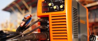
In a short time, inverter welding machines have gained unprecedented popularity among specialists. Despite the reliability of the power supply, repair of a welding inverter may sometimes still be necessary. Diagnosis of a malfunction and replacement of a failed part, if you have some skill, can be done at home. To carry out repairs, you must first familiarize yourself with the design of the device and only then proceed with the repairs.
Equipment delivery
Repair of welding equipment is carried out only after diagnostics, which is possible only in a service center. In addition, after eliminating the malfunction, testing is required within several hours. This approach guarantees customers the quality of work performed and spare parts installed.
If necessary, service center specialists will provide assistance in disconnecting and connecting equipment, and will also organize delivery: mobile teams consisting of several people will go to the site, disconnect the equipment and deliver it to the service center. Upon completion of the repair work, the equipment will be delivered to the customer and the necessary measures will be taken for further operation. Alternatively, you can use a courier service.
The cost of equipment delivery is negotiated with each customer individually.
The main reasons for the failure of inverters and their manifestations
The main reasons for the failure of welding inverters are violations of the rules of their operation. You can learn about the operating modes and maintenance features of a particular device from its passport; in general, approximately the same list of activities is given:
- daily external inspection of the main unit and cables;
- periodic internal cleaning of the device with compressed air;
- routine inspection, cleaning, pulling and repair of connections of internal power contacts;
- measuring insulation resistance and checking protective grounding circuits.
The main factors that cause inverter malfunction are:
- Sudden changes in input voltage. Its fall leads to instability and termination of the inverter's operation, while a significant excess can cause failure of the elements of the input rectifier.
- Mineral dust. Covers the surfaces of the internal parts of the device and clogs the ribbed surfaces of radiators for cooling diodes and transistors. This leads to a violation of the thermal regime and can cause failure of individual elements.
- Metal dust and fine shavings. It gets inside the inverter through the input fan if work is being done next to it with grinders, grinders, etc. It can cause an internal short circuit.
- Water and high humidity. Causes oxidation of wires and contacts and can lead to a short circuit.
- External mechanical damage. Sometimes they cause failure of controls and internal structural elements on which electronic components are attached.
The following describes the main malfunctions in the operation of inverters and their causes.
Arc instability, metal spatter
If there are significant fluctuations in the input voltage or incorrect operation of the inverter control system, abrupt changes in the welding current occur, which leads to arc instability. In this case, first of all it is necessary to check the network voltage. If it is normal, but the oscillations continue, internal diagnostics of the inverter should be performed.
Spattering of metal during welding is usually a consequence of incorrect selection of welding current. The reason for this may be either a human factor or a malfunction of the current regulator or control system.
Inverter does not turn on
This phenomenon may have several reasons:
- poor contact of the ground cable clamp;
- input voltage too low;
- the input circuit breaker has turned off (the reason for this may be an internal short circuit);
- The thermal protection has tripped.
In the latter case, you need to wait until the device cools down and try to turn it on again. If the protection trips repeatedly, the inverter requires maintenance or repair.
Inverter overheating
The main reason for overheating of the inverter is a violation of thermal conditions due to a large amount of dust in the internal space of the device. Dust acts as thermal insulation, covering the surfaces of components cooled by the air flow, and does not allow fans to operate normally. If there is constant overheating, before talking about diagnostics and repairs, it is necessary to carefully and very carefully clean all internal modules with compressed air. Another reason for overheating of the inverter is non-compliance with the recommended value of the PV parameter (on duration).
Figure 3 - PV parameters
Increased power consumption
Increased power consumption at idle at the standard value of the input voltage of the network is usually associated with a short circuit between the turns of one of the windings of the high-frequency transformer. Externally, such a malfunction looks like burning of the insulation around its live parts and is most often accompanied by a drop in the no-load voltage (sometimes by two to three times). It is not difficult to remove, disassemble and inspect the transformer yourself, but it is better to entrust its repair to someone who is well versed in this.
Electrode sticking to metal
If the electrode sticks during the welding process, most likely this is caused by incorrect selection of technological parameters and poor preparation of the surfaces to be welded. In addition, to prevent this phenomenon, all modern inverters are equipped with an automatic Anti-Stick function. When the value of the welding current corresponds to the diameter of the electrode and the thickness of the metal being welded, and the welding zone is cut and cleaned properly, the cause of sticking (sticking) may be a periodic decrease in voltage both from the electrical network and directly in the welding circuit.
In the first case, it is necessary to stabilize the mains power supply or use an inverter with the ability to operate at reduced voltage. On the welding chain side, the contacts must be periodically cleaned and their reliability checked. In addition, a voltage drop can be caused by the use of cables whose length and cross-section do not meet regulatory requirements.
Inability to adjust current
First of all, we can talk about a malfunction of the indicator that displays the current value. Also, one of the most common reasons is a broken wire, breakdown or internal wear of the potentiometer, which sets the value of the welding current. If all this is in order, then the problem may be a malfunction of the inverter control system. Only an experienced specialist can understand it and perform such repairs.
Spontaneous shutdown
The reasons for sudden shutdowns of the welding inverter can be sudden surges in the supply voltage, a malfunction of the input circuit breaker, and the operation of temperature protection. In the first case, it is necessary to somehow stabilize the input voltage or use a device designed to operate in this range. If the temperature protection is frequently triggered, it is necessary to clean the internal part from dust and check compliance with the manufacturer's recommendations for the duration of continuous operation. You can check the serviceability of the input machine without complex repairs by temporarily connecting a known-good device instead.
Repair speed of welding equipment
To solve a problem related to a malfunction of the welding machine, it will take from 3 days to two weeks. The service center always has in-demand spare parts in stock; Deliveries from time-tested manufacturers are carried out daily.
In the event of a microprocessor failure, repair work may take a little longer: spare parts are supplied to order from the equipment manufacturer after diagnosis. The exact timing of repairs depends on the date of receipt of delivery.
It is important to note that our technicians work not only on weekdays, but also on weekends. This is due to the lack of active traffic on the roads: it is easy to get to the service center without traffic jams. Delivery of the welding machine will also be much faster.
Repair work for regular customers on weekends is carried out at a discount.
General procedure for diagnosing welding inverters
Before repairing the device, you should check the functionality of the cooling system. Cooling radiators clogged with dust remove heat from the power elements much worse, which means the fins should be completely cleaned of dust and other debris.
Repair of inverter welding machines should begin with diagnosing the input rectifier.
To fully check this node you should:
- disassemble the module;
- remove the radiator;
- remove the diode bridge;
- ring the contacts of the diode bridge.
If no problems with the diode bridge are identified, you should move on to the next module - the output rectifier.
Typical inverter faults.
The functionality of the output rectifier is checked using the following algorithm:
- disassemble the module;
- unsolder the diode assemblies;
- ring the diodes.
In addition to diodes, the output rectifier circuit contains radiators that should be installed back after repairing the module.
After examining the output rectifier, you should proceed to diagnosing the key module.
This inverter module consists of:
- four groups of transistors;
- key control boards;
- smoothing rectifiers.
The procedure for examining the key module is as follows:
- Checking transistors. As a rule, a faulty element is clearly visible to the naked eye. If this is not the case, then you should check the sequence of all available transistors with a tester.
- If measurements with a tester do not produce results, you need to diagnose the transistor assemblies using an avometer, measuring the resistance.
- If all components appear to be in good working order, all transistors should be unsoldered one by one. This diagnostic method is suitable if there is a short circuit on the board.
If the transistor converters of the control unit are fully operational, you need to inspect the key control board. To carry out such diagnostics, you should prepare an oscilloscope.
Most inverter problems can be diagnosed by carefully inspecting the electronic components. If defective parts are identified, you should immediately remove them and replace them with similar characteristics.
Payment Methods
The convenience of cooperation with us is due to the fact that we offer clients several methods of payment for work performed: cash and non-cash payments, bank transfer. When interacting with legal entities, an invoice is issued and the necessary package of documents is prepared.
Please note that we do not accept payments through electronic wallets and payment systems.
The cost of urgent repair work doubles; This service is at the discretion of the client.
General information
The inverter is a product of the development of semiconductor technologies, for example, Cascade and Laurel. Compared to transformers, they compare favorably with the following parameters:
- Light weight;
- Compact dimensions;
- Seam quality;
- Economical energy consumption;
- Additional functions.
For home use, the main disadvantage of transformers is the increased requirements for the power supply network, since the power of these devices is very high, sometimes reaching 8 kW. In addition, their operation is accompanied by numerous voltage surges, which negatively affect the integrity of the wiring and can damage household appliances powered by electricity.
Thanks to the last point, inverters are valued by novice welders, because they can facilitate the process of joining materials. The following functions are implemented on modern devices:
- Hot start . Simplifies arc formation by increasing the current level before starting work.
- Anti-stick electrode . If there is a danger of sticking, the current level is automatically reduced, allowing the connection to continue.
- Arc Force . As the arc length increases, the automation independently regulates the current strength, preventing breakage. This function is especially useful when the seam is directed vertically.
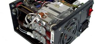
Design and operating features
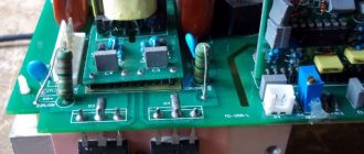
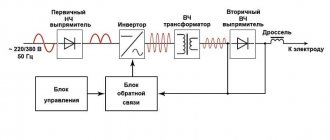
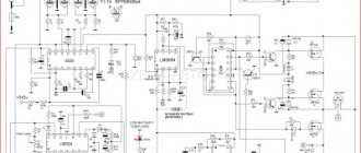
Schematic diagram of a welding inverter.
Inverters produce high-frequency current, due to which the welding arc is stable and the seam has a uniform structure . The operating principle is based on multiple conversion of electrical energy. As a result, the voltage decreases, and the current increases and rectifies, converting into direct current. It is used to perform connection work.
To repair welding machines, you need to have an understanding of the structure of the equipment. The main components of the units under consideration are:
- Power unit . It is responsible for providing energy to the power part of the device. Consists of a rectifier, a nonlinear charging circuit and a capacitive filter.
- Power point . Includes inverter, secondary rectifier, power transformer and output choke.
- Power supply for device devices operating at 12 V.
- Pulse width modulation . Power control device.
- Protection mechanism . It consists of sensors responsible for temperature control, as well as cooling fan drives.