No transformer can operate without power loss. The power supplied to the primary winding from the network does not all reach the consumer. Part of it is spent on useless heating of the unit parts: windings, magnetic circuit. In order to evaluate power losses, the no-load current of the transformer (OC) and the voltage in short-circuit mode are assessed.
To measure these values, an open-circuit and short-circuit experiment is carried out for the transformer. Let's take a closer look at how this is done.
Methodology and theoretical basis for conducting the experiment
The idle mode of the transformer is achieved relatively simply. To do this, it is enough to disconnect the load from all its windings, leaving them open, and then turn it on to the network. For the accuracy of the experiment, it is desirable that the network voltage be equal to the nominal voltage for a given unit.
A current Io flows through the primary winding, called current XX. Its value does not exceed 3-10% of the nominal value. Let us remind you that there is no load on the secondary winding, so it is worth explaining the processes taking place inside in order to understand where this current comes from.
Current XX creates a magnetic flux Fo in the magnetic core, crossing the turns of the primary and secondary windings. Due to it, a self-induction emf E1 appears on the primary winding, and a mutual induction emf E2 appears in the secondary winding.
Self-induction emf E1 has little effect on the primary voltage U1. If you connect a voltmeter to it, it will measure the value of U1. And the emf E2 can practically be considered the voltage U2, since there is no load current. For example, the no-load voltage of a welding transformer is about 60V, this is emf E2. When an arc occurs, E2 sharply drops to tens of volts - this is the value under load U2.
Net power losses in a transformer during its operation are divided into two components: losses in copper and losses in steel. Copper loss refers to the power dissipated as heat in the windings. When conducting the XX experiment, the current through the primary winding is quite small, and losses in copper can be neglected.
Operation of a transformer in idle mode is accompanied by power consumption to create a closed magnetic flux in its magnetic circuit. This is called the loss power in steel. It goes to heating the magnetic circuit plates. It is assembled from individual thin sheets of a special alloy, insulated from each other with varnish. No welding is used during assembly, only bolted connections. This is done to minimize eddy currents that occur due to the fact that the magnetic flux is variable.
If the insulation between the plates is broken, the eddy currents arising between them heat the magnetic circuit. This leads to further destruction of the varnish layer. At the same time, the power losses in the steel increase, which will increase the no-load losses of the transformer.
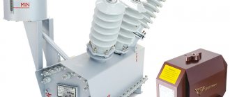
Installation and adjustment of the equipment complex before switching on
In the process of inspecting the installation site and setting up the equipment before turning it on, it is important to assess the extent to which safety regulations are being followed. The installation should not pose a threat to the normal movement of maintenance personnel (including equipment). If the power transformer is installed at ground level, check the physical and mechanical characteristics of the soil and its continuity. Identified non-compliance with regulations may cause ground movement, resulting in damage to the transformer or its electrical connections. If the transformer is installed on a concrete pad, then the maximum shear stress of the material should be 20 MPa or more. The geometric shape of the platform is also controlled: it must have beveled edges at the top and bottom, the height of which from each end must be at least 50 mm. The minimum dimensions of a concrete base (concrete grade not lower than M400) for power transformers with a capacity of 500...2500 kVA are: length - 2400 mm, width - 2700 mm, height - 250 mm.
If the device is installed indoors or on the roof of a building, it is necessary to carefully analyze the possible behavior of the structure under load and assess the risks of damage to integrity. Special provisions apply to devices that are located in seismically hazardous areas.
During such work, the actual layout of the transformer is constantly compared with the one given in the equipment manufacturer’s instructions.
Important! All identified inconsistencies must be immediately corrected by the construction company responsible for installing the device.
Transformation ratio
For a transformer there is the concept of transformation ratio, the formula of which is:
Ktr = E1/E2 = W1/W2
As a result, the voltage that will be at the terminals of the secondary winding is determined by the ratio of the number of turns of the windings. This property is used to adjust its output value.
For this purpose, the design includes a regulating device that stepwise switches the number of turns of the primary winding. It has 3 to 5 positions for adjustment, and the output voltage with each adjustment step changes by 5% higher or lower than the nominal one. The switching device is called an antzappa.
[ads-pc-1][ads-mob-1]
Experiment XX is carried out at the middle position of the trunnion, corresponding to the nominal value.
When conducting experiment XX, the transformation coefficient is measured. For this, two voltmeters are used. One of them is connected to the primary winding and measures U1. The second one is connected to the secondary winding, it measures the emf XX. The input resistance of the voltmeter must be large enough so as not to affect the measured value. Dividing the voltmeter readings gives the transformation ratio.
Transformer - can operate both step-up and step-down. Therefore, when carrying out repair work on it, it is used to supply not only high voltage to the HV winding, but also low voltage to the LV winding. Even if it is an instrument transformer that has a small secondary voltage of 100 V.
We examined the no-load operation of a single-phase transformer. For three-phase devices, the transformation ratio is measured on all three phases, for which either 6 voltmeters are used simultaneously, connected to the linear voltages of the three-phase system, or one connected to the measurement points one by one.
If the rated supply voltage of the primary winding is high (6 kV and above), then 380 V is supplied to the primary winding. For high-voltage measurements, it is impossible to use instruments with the appropriate accuracy class. In addition, the measurement process at low supply voltage is safer.
The coefficient must be measured at all positions of the antzapf.
Transformation ratio is an indicator indicating whether there is a turn short circuit in the windings. A scatter of phase readings of more than 2% or a decrease in comparison with previous data gives reason to believe that the insulation of the winding conductors is broken somewhere. Suspicion will require confirmation by other test methods, such as resistance measurements. Also, the reason for the increase in the spread of the transformation ratio may be the increased resistance between the contacts of the switching device - the axapf. Which is what happens most often, especially if it is used often.
The principle of operation of a transformer in idle mode
When a sinusoidal voltage is applied to the winding of the device, a weak current appears in it, usually not exceeding 0.05-0.1 of the rated value (this is the no-load current). It is created by a winding magnetomotive force; it is because of its action that a leading magnetic flux (denoted F) and a scattering flux F1, closed around the winding body, arise in a closed magnetic conductor element. The value of the magnetomotive force is equal to the product of the no-load current and the number of winding turns.
Transformation ratio
The leading flow creates two electromotive forces in the device: self-induction in the first winding and mutual induction in the second. F1 produces a leakage emf at the first coil. It has a very small value, because the flow that creates it is closed, for the most part, through air masses, the leading flow F is through the magnetic circuit. Since the main flow has a much larger scale, the electromotive force it generates for the primary coil is also much larger.
Important! Since the supplied voltage has the form of a sinusoid, the main flow and the winding electromotive forces it creates have the same characteristics. But due to magnetic saturation, the flux present in the device is disproportionate to the electric current that creates magnetization, so the latter will not be sinusoidal. It is practiced to replace its real curve with a corresponding sinusoid with the same value. Current distortion is associated with the third harmonic component (a value determined by eddy flows and magnetic saturation).
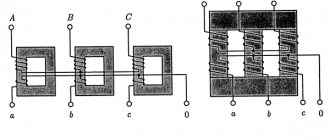
No-load three-phase transformer
The functioning of such a device in the considered mode depends on the design of its magnetic system. If a device similar to a group of single-phase transformers or an armored rod system is used, the third harmonic component for each phase will be closed in a separate core, gaining a value of up to 20% of the active magnetic flux. An additional electromotive force is created that can reach a very high value - 0.5-0.6 of the main EMF. Such processes can cause a violation of the integrity of the insulation, followed by breakdown of the electrical installation. The best option is a system with three rods, then the third component will not go along the magnetic circuit, but will be closed in air or another medium with a low magnetic permeability (for example, oil). In this case, a massive additional EMF, introducing serious distortions, will not develop.
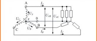
Scheme of no-load experiment of a three-phase two-winding transformer
Transformer efficiency calculation
Energy losses in the device, occurring in copper and steel components, cause a discrepancy between the output and consumer power parameters. You can find out how efficient a device is by calculating its efficiency: it is equal to the quotient of the output and consumed values. The latter is equal to the sum of the first, losses for the steel core (they are determined during the no-load experiment) and for copper elements (calculated from measurements of the short-circuited device).
Conducting short-circuit and short-circuit tests is a reliable way to calculate the efficiency of a transformer. It also allows you to determine the volume of energy losses and find out which component accounts for most of them.
Loss table
Features of operation and application of the Tesla resonant transformer
When the second coil circuit is open, it does not use any operating power. The power that the first one consumes has a certain active percentage (this represents the losses of the device), but the reactive one, responsible for magnetization and given to the generator, dominates. As for the lost power, most of it is spent on magnetization reversal processes and the generation of magnetic circuit current eddies. Because of this, the latter begins to overheat. Since the leakage flux does not depend on the load electric current, there are power losses not only at idle, but also when applying loads. Another part of the losses (very small) is spent on heating the coil wire. Its low value is due to the wiring resistance and no-load current.
At a voltage of 10/0.4 kV, the amount of losses will increase as the power increases. For a rated power of 250 kVA, the losses will be 730 W, for 400 kVA - 1000 W, for 2500 kVA - 4200 W. After years of operation, processes occur in the magnetic circuit that increase the amount of losses: the insulation wears out, the structural characteristics of the metal change. Because of this, up to 50% of power can be lost.