When, according to the conditions of the drawing, it is necessary to obtain a smooth and shiny mirror surface of a part, but the dimensional accuracy may be rough, polishing of this surface is used; if, in addition to cleanliness and shine, it is necessary to obtain the exact dimensions of the part, finishing or lapping is used.
Polishing
Polishing is carried out on lathes using emery cloth.
. Depending on the size of the emery grains, the following sandpaper numbers are distinguished: No. 6, 5 and 4 - with large emery grains, No. 3 and 2 - with medium ones, No. 1, 0, 00 and 000 - with small ones. The cleanest polishing is achieved with sandpaper No. 00 and 000. The sandpaper should be held as shown in Fig. 232, otherwise it may wrap around the part and pinch your fingers.
Polishing is done much faster with the help of a simple device called a press (Fig. 232, b). The presses consist of two wooden blocks connected at one end by a leather or metal hinge and having recesses in the shape of the part. Sandpaper is placed in the clamps or sanding powder is added. It is recommended to lubricate the surface to be polished with machine oil or mix powder with oil, then the surface will be more shiny.
The use of clamps eliminates the risk of injury to the turner’s hands and of the sleeve being caught by a rotating part, clamp or chuck.
Polishing is carried out with light pressure of the presses and high speeds of the workpiece.
Finishing or lapping
Finishing or lapping is used for final processing of external and internal cylindrical and conical, shaped and flat surfaces of parts in order to obtain accurate dimensions and high quality (cleanliness) of the surface or tightness of the connection.
This processing method has become widespread in tool production (finishing the cutting edges of carbide cutters and reamers; finishing cylindrical, conical, threaded gauges; finishing measuring tiles).
This processing method is also widely used in mechanical engineering, for example, finishing of crankshaft journals, injector plungers, wheel teeth, etc. The surface finish after finishing can be obtained from 10 to 14.
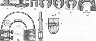
The finishing of the outer cylindrical surfaces is carried out using cast iron, copper, bronze or lead bushings (laps), machined to the size of the workpiece. On one side the bushing is cut, as shown in Fig. 233.
Bushing 1 is lubricated from the inside with an even thin layer of corundum micropowder with oil or finishing paste. Then it is inserted into the metal clamp 2 and put on the part. Slightly tightening the clamp with bolt 3, rub evenly along the rotating part. When finishing, it is useful to lubricate the part with liquid machine oil or kerosene.
The finishing allowance is left on the order of 5-20 microns (0.005-0.020 mm) per diameter.
The speed of rotation of the part during finishing is from 10 to 20 m/min; The cleaner the treated surface should be, the lower the speed should be.
The holes are finished using cast iron or copper bushings (laps), also cut on one side. The bushings are set to the exact size using flat conical mandrels onto which they are mounted. In Fig. 234 shows a sleeve 1 mounted on a conical mandrel 2 fixed in a self-centering chuck. For finishing, the part is put on sleeve 1, which rotates with mandrel 2 during finishing; in this case, the parts communicate a slow rectilinear-return movement along the bushing.
Finishing of external and internal surfaces is carried out with corundum micropowder mixed with oil, or with special GOI finishing pastes. These pastes give better results both in terms of surface quality and performance. They have not only a mechanical but also a chemical effect on the metal. The latter is that thanks to the paste, a thin film of oxides is formed on the surface of the part, which is then easily removed.
Rolling
The cylindrical handles of various measuring instruments, caliber handles, micrometer screw heads and round nuts are made not smooth, but grooved, to make them easier to use. This corrugated surface is called knurling.
, and the process of obtaining it is
by rolling
.
Knurling can be straight or cross. Read also: Thermal conductivity of steel at different temperatures
For rolling, a special holder 1 (Fig. 235) is fixed in the tool holder of the machine support, in which one is installed for simple rolling, and for cross rolling - two rollers 2 and 3 made of tool hardened steel with teeth applied to them .
The teeth on the rollers have different sizes and different directions (Fig. 236), which allows you to produce different knurling patterns.
When rolling, the holder is pressed against the rotating part. The rollers rotate and, pressing into the material of the part, form a knurling on its surface. It can be large, medium or small depending on the size of the teeth on the rollers.
When rolling, feed is performed in two directions - perpendicular to the axis of the part and along the axis. To obtain sufficient knurling depth, knurling can be carried out in 2-4 passes.
Rules for rolling: 1) when starting rolling, you should immediately apply strong pressure and check whether the teeth of the roller fall into the notches they made during the next revolutions; 2) the rollers must match the required pattern of the part; 3) double rollers must be precisely located one below the other; 4) before work, the rollers must be thoroughly cleaned from any remaining material with a wire brush; 5) during rolling, the working surfaces of the rollers should be well lubricated with spindle or machine oil.
Rolling modes. In table 10 and 11 indicate peripheral speeds and longitudinal feeds when rolling on lathes.
The correct knurling is checked by eye.
Rolling the surface with a roller
To strengthen the surface layer of a part pre-processed, for example, by fine turning, rolling a cylindrical surface with a hardened roller with a polished surface is used.
The rolled part is given a rotational movement at a speed of 25-50 m/min, and the holder with a roller is given a longitudinal feed movement. The feed rate is 0.2-0.5 mm/rev - depending on the required surface cleanliness. Rolling is carried out with slight pressure of the roller on the rolling surface. The number of roller passes is 2-3. To reduce roller wear, generously lubricate the surfaces of the roller and the part with spindle or machine oil mixed in equal quantities with kerosene.
Technology
The process itself consists of several stages. The algorithm is as follows:
- Preparatory stage. At this time, the surface of the product is polished and all dirt, dust, and lint are removed from it. When grinding, abrasives with different grain sizes are used.
- Surface primer. it is carried out using linen fabric and varnish. Linen fabric is best suited because it does not leave small fibers on the workpiece.
- At the third stage, the product itself is polished. After applying the special substance, the flax tampon should be soaked in vegetable oil and cover the product with an even layer. Each new layer of polish must dry, after which it should be wiped with a rag to remove dust and give the surface an ideal appearance.
The final stage is polishing.
Surface finishing methods
For surface finishing fine turning and boring, fine grinding, polishing, honing, superfinishing, lapping , abrasive-liquid finishing, methods of finishing tooth profiles are used: running in gears, shaving teeth, lapping, gear grinding and gear rounding.
A characteristic feature of all finishing cutting methods is the very small cross-sectional size of the cut chips and, consequently, low cutting force. For the rational use of finishing methods, good pre-treatment of the surface and leaving a very small allowance are necessary.
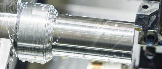
Fine grinding of surfaces is carried out with carbide cutters at small sections of the cut layer (S = 0.02 - 0.5 mm/rev, t = 0.05 - 0.3 mm and at high cutting speeds V > 100 m/min). In such cases, significant effort is not required to secure the workpiece: the cutting force is small, little heat is generated, and the thickness of the defective layer on the machined surface is very small. Since work of this kind is usually carried out on hard and precise machines, as a result of all these conditions, higher accuracy and surface finish are achieved during fine turning than during normal turning (accuracy up to class 2 and cleanliness up to class 9).
Fine boring of surfaces gives higher accuracy and finish of processing than ordinary boring. Fine boring is carried out with boring cutters equipped with plates made of T30K4 or T60K6 alloys, at high cutting speeds (V = 300 ÷ 1500 m/min for non-ferrous metals and 100 ÷ 300 m/min for ferrous metals) and with small sections of the cut layer (S = 0.01 ÷ 0.1 mm/rev, t = 0.05 ÷ 0.2 mm). For fine boring, very precise machines with significant rigidity are used.
As a result of all these conditions, fine boring makes it possible to obtain very high accuracy (up to class 1 according to GOST) and machining cleanliness (up to class 10 according to GOST), maintain the hole shape within 3 microns and coordinating dimensions within 0.02 mm per 100 mm length both through and blind holes.
When machining holes in thin-walled steel workpieces, as well as when machining very tough non-ferrous metals, fine boring is the best way to meet high technical requirements.
Fine grinding is a method of final finishing of surfaces with a high degree of precision and cleanliness of processing.
Features of fine grinding are:
- use of fine-grained soft grinding wheels;
- grinding with cutting depth up to 5 microns;
- work at low peripheral speed of the processed surface (about 2÷10 m/min) and high rotation speed of the grinding wheel (more than 40 m/sec);
- application of the most intensive cooling;
- long-term curing, i.e. surface finishing without cross-feed of the wheel.
Fine grinding on hard machines makes it possible to obtain processing accuracy of the 1st class and surface cleanliness of the 11th class of GOST.
Tips and tricks
In order for the wood to better accept the polish, it must be lubricated with etching. You can make this composition yourself or purchase a ready-made one. Dark wood must be lubricated with stain several times. Light - once.
You can make your own polishing composition at home. For this you will need:
- 60 g shellac resin;
- ethyl alcohol or wine alcohol with a strength of 90–95° in a capacity of 500 ml.
The prepared polish should be stored in a closed glass container. The mixture must be stirred regularly.
Polishing on a lathe is much faster if you use presses. This is a device made from two wooden blocks. Sandpaper is placed there or powder is added.
Surface finishing methods
General information.
Finishing refers to processing methods designed to achieve particularly high surface precision. These methods include fine turning, honing, lapping, polishing, superfinishing, and smoothing. Finishing operations are characterized by the removal of very small allowances. A small allowance does not allow a significant change in the position of the surface occupied by it before finishing. Therefore, with the exception of fine turning, all finishing methods are characterized by a self-aligning final connection, i.e., they are designed to improve only the processing accuracy. Finishing is most often used to improve the accuracy of a surface only in shape and roughness, and even only in roughness, since a given dimensional accuracy rarely requires finishing methods. The required small allowance is provided by allowing for the final surface size.
Fine turning.
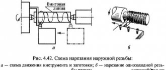
The fine turning process is characterized by small depth of cut, low feed rate and high cutting speed. Processing is carried out with a diamond or carbide cutter.
Fine turning is used mainly when processing parts made of non-ferrous alloys, since these alloys are easily processed with a cutter, but do not behave well when processed with an abrasive tool.
Turning with a diamond cutter makes it possible to automatically obtain dimensions to ensure surface accuracy: in diameter - up to grade 5 accuracy; in shape - ovality and taper, not exceeding 0.003-0.005 mm; in terms of roughness - up to Ra 0.16.
High accuracy is achieved due to the low wear of the finished cutter blade (the durability of a diamond cutter is 200-400 hours), low forces during the cutting process and high precision of the equipment. High cutting speed not only compensates for the decrease in productivity due to low feed, but also helps to reduce the roughness of the machined surface.
For fine turning operations, machines for a specific purpose are used, but along with them, lathes that have the necessary kinematic data and accuracy are used. Cutters made of hard alloys are used for processing steels and cast iron, as well as for rough turning of non-ferrous alloys, when the fine turning operation is divided into two transitions - roughing and finishing.
Fine turning is most widely used for machining precise holes in parts made of non-ferrous alloys. The difficulties of grinding (grinding of the wheel) especially increase here (small wheel diameter); deployment is also ineffective and, moreover, does not allow influencing the coordinates of the hole axis. Fine boring allows you to influence the accuracy of size and shape, ensures high stability of processing quality and good productivity. For this purpose, boring machines are produced in which it is not the part that rotates, but the cutter (due to the speed, it is important that the load on the spindle be less). For small parts, horizontal boring machines are used, and for large parts, vertical boring machines are used.
The smallest allowance, evenly distributed around the circumference of the hole, can be achieved by horizontal boring machines on both sides. On such a machine, with one installation, the parts are rough boring on one side, and finishing on the other.
For operations of boring holes with parallel axes, multi-spindle machines are used, which allow setting the required distance between the spindle axes, as well as special machines manufactured as aggregate ones.
Honing.
Honing is widely used for making holes. The processing tool is an expanding head - hone, which carries abrasive (or diamond) bars around its circumference (Fig. 5.23). The bars are fixed in metal blocks and, using the head mechanism, can be expanded in radial directions. The head is connected to the spindle of the honing machine not rigidly, but hingedly, so that it can self-align along the workpiece hole mounted on the machine table.
The head inserted into the hole is subjected to rotation (V = 30 - 60 m/min) and reciprocating movement (V = 10 - 15 m/min). The decompression of the bars during processing is carried out automatically or manually (the head is a special tool, so their designs are varied). The pressure of the bars on the surface is small (0.4 – 0.8 MPa). During processing, abundant cooling with kerosene is used, often mixed with mineral oil. The usual honing time is 1-5 minutes.
The allowance (metal layer) removed in one honing operation can be small (up to 0.01 mm) and relatively large (up to 0.2 mm). It is determined by the accuracy of the previous processing and the surface accuracy required after honing.
Possible mistakes
First of all, it is important to secure the workpiece. If the part is not securely fastened, the quality of grinding and polishing will be poor.
Be sure to follow safety rules when working with a lathe. It is prohibited to allow children and persons unfamiliar with the operation of the lathe to access the equipment.
The process of polishing wood products on a lathe consists of several stages and allows you to give the workpiece its final appearance, rich color and depth. It is important to correctly observe all the features of the process and select the composition for polishing.
Application of polishing for finishing
For finishing, several methods are used, for which substances are used:
- varnish;
- varnish;
- drying oil;
- wax paste.
When finishing wood products, when varnish is used for polishing, a protective layer is formed that gives the surface a marketable appearance. The polishing process involves applying a special polish composition containing three times less resin than varnish. The coating formed on wood has a transparent structure and a glossy tint.
When choosing a finishing and polishing method, the type of wood must be taken into account. The most suitable types of wood for making furniture are:
- mahogany;
- birch;
- pears;
- boxwood;
- maple;
- apple trees
Also widely used, but quite labor-intensive in processing the rock:
- oak;
- pine trees
Description of the lathe
A wood lathe has one limiting function: it can only rotate a piece of wood. A carpenter is capable of slowly turning a finished object from an ordinary piece of wood, for example:
Unlike other woodworking machines, which are used only at certain intermediate stages, a lathe is suitable for any operation: from pre-processing to polishing. The necessary tools are grooved (V-shaped or cylindrical) and flat scrapers, cutters, chisels of various shapes and sizes. The machine rotates the workpiece, and the master’s hand controls the movement of the cutter. Based on what item needs to be made, there are two options for attaching the workpiece.
In the first case, the wooden part is mounted in a horizontal position between the centers of the front and rear walls. The second method takes into account that the wood turner secures the workpiece only in the headstock using a faceplate or chuck. If you are new to working with this machine, it would be wise to start using the first method.
Lathe with electronic adjustment (equipment):
Equipment option:
- grooved chisel,
- Maisel cutter (2 mm),
- semicircular cutter,
- cutting cutter,
- beveled chisel (jamb),
- semicircular chisel - for finishing shaped surfaces,
- grooved chisel (reyer) - for roughing.
Principle of operation
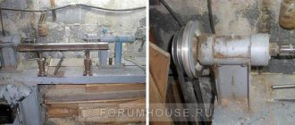
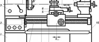
The entire structure of the machine is mounted on a frame, which is made of aluminum, cast iron or profile beams or two steel bars. On one side of the bed, the wood turner places the headstock, and inside it there is an electric motor (0.5-1.5 horsepower). It rotates a spindle having a Morse taper; if necessary, a driving center (with one tip and 2, 3 or 4 knives), a faceplate or a chuck is inserted. The tailstock is located on the opposite side of the machine, and its center presses the workpiece, securing it in a horizontal position.
Hand rest that can be turned in any direction
, is located as close as possible to the blank, guides the cutter and supports it.
On machines with manual adjustment, the frequency (speed) of movement can be switched using the gearbox lever, the speed of which is from 450 to 2000 rpm. It contains pulleys with bearings.
In much more complex modifications of the machines, instead of a gearbox, there is an electronic variator, which makes it possible to gently regulate the speed of movement.
