BRANDS / CHARACTERISTICS of KM pumps
There are DISCOUNTS! CALL +7-953-812-16-31!!!
| Name | Supply, m3/h | Head, m | Engine, kW/rpm | In. pipe, mm | Exit pipe, mm | Dimensions, mm | Weight, kg |
| KM50-32-125 | 44328 | 20.0 | 401801 | 50.0 | 32.0 | 500x230x190 | 47.0 |
| KM50-32-125/2-5 | 44328 | 20.0 | 401801 | 50.0 | 32.0 | 500x230x190 | 47.0 |
| KM50-32-200/2-5 | 44328 | 50.0 | 401893 | 50.0 | 32.0 | 70.0 | |
| KM65-50-125 | 25.0 | 20.0 | 3.0/3000 | 65.0 | 50.0 | 550x272x210 | 62.0 |
| KM65-50-125/2-5 | 25.0 | 20.0 | 3.0/3000 | 65.0 | 50.0 | 550x272x210 | 62.0 |
| KM65-50-160 | 25.0 | 32.0 | 401893 | 65.0 | 50.0 | 578x272x230 | 75.0 |
| KM65-50-160/2-5 | 25.0 | 32.0 | 401893 | 65.0 | 50.0 | 578x272x230 | 75.0 |
| KM80-65-160 | 50.0 | 32.0 | 401895 | 80.0 | 65.0 | 635x435x265 | 105.0 |
| KM80-65-160/2-5 | 50.0 | 32.0 | 401895 | 80.0 | 65.0 | 635x435x265 | 115.0 |
| KM80-50-200 | 50.0 | 50.0 | 15/3000 | 80.0 | 50.0 | 790x720x265 | 185.0 |
| KM80-50-200/2-5 | 50.0 | 50.0 | 15/3000 | 80.0 | 50.0 | 790x720x265 | 185.0 |
| KM80-50-250/2-5 | 50.0 | 80.0 | 22/3000 | ||||
| KM100-80-160 | 100.0 | 32.0 | 15/3000 | 100.0 | 80.0 | 790x420x280 | 185.0 |
| KM100-80-160/2-5 | 100.0 | 32.0 | 15/3000 | 100.0 | 80.0 | 790x420x280 | 195.0 |
| KM40-32-200/4-5 | 44261 | 12.0 | 1.1/1500 | 40.0 | 32.0 | ||
| KM40-25-160/2-5 | 44261 | 32.0 | 401801 | 40.0 | 32.0 | 46.0 | |
| KM40-32-180/2-5 | 10.0 | 45.0 | 3.0/3000 | 40.0 | 32.0 | 502x297x280 | 48.0 |
| KM100-65-200 | 100.0 | 50.0 | 30/3000 | 100.0 | 65.0 | 865x460x320 | 260.0 |
| KM100-65-200/4-5 | 50.0 | 44328 | 4.0/1500 | 100.0 | 65.0 | 865x460x320 | 150.0 |
| KM100-65-200/2-5 | 100.0 | 50.0 | 30/3000 | 100.0 | 65.0 | 865x460x320 | 270.0 |
| KM100-65-250 | 100.0 | 80.0 | 45/3000 | 100.0 | 65.0 | 865x460x320 | 265.0 |
| KM100-65-250/2-5 | 100.0 | 80.0 | 45/3000 | 100.0 | 65.0 | 865x460x320 | 265.0 |
| KM100-65-250/4-5 | 50.0 | 20.0 | 5.5/1500 | 100.0 | 65.0 | 865x460x320 | 265.0 |
| KM150-125-250 | 200.0 | 20.0 | 18.5/1500 | 150.0 | 125.0 | 895x705x400 | 265.0 |
| KM150-125-250/4-5 | 200.0 | 20.0 | 18.5/1500 | 150.0 | 125.0 | 895x705x400 | 265.0 |
| KM150-125-315/4 | 200.0 | 32.0 | 30/1500 | ||||
| KM125-100-160/2-5 | 160.0 | 30.0 | 22/3000 | 125.0 | 100.0 | 255.0 | |
| KM125-100-250/4-5 | 100.0 | 20.0 | 11/1500 | 125.0 | 100.0 | 450.0 | |
| KM160/20-5 | 160.0 | 20.0 | 15/1500 |
WIKI — > Cantilever pumps types K, KM
Type K pumps are centrifugal horizontal cantilever, single-stage pumps made with support on the housing and on the stand; the pump and electric motor are mounted on a common frame; drive from an electric motor - through an elastic coupling.
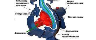
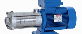
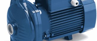
Pumps of the KM type are monoblock pumps with a one-way supply of liquid to a closed-type impeller, the impeller is mounted directly on the extended end of the shaft of a special asynchronous electric motor.
PUMPS OF TYPES K, KM ARE APPLIED:
- at pumping stations of urban, industrial and rural water supply - for drainage,
- irrigation and irrigation of land, for pumping water and neutral liquids.
- Pumped media – fresh water (drinking and technical) and non-explosive liquids similar to water in density, viscosity (up to 36 cSt) and chemical activity; with pH from 6 to 9%.
TEMPERATURE OF PUMPED FLUID:
- with a mechanical shaft seal – from 273K to 388K (from 0°C to + 105°C);
- with a single shaft seal - from 273K to 358K (from 0°C to + 85°C).
Content of mechanical impurities: by weight – no more than 0.15%; particle size – no more than 0.2 mm. The liquid should not contain fibrous materials, ash, slag, sand or other fillers. The permissible vacuum suction height is up to 5...7 m.
MATERIALS FOR CONSTRUCTION OF PUMP FLOW UNITS:
- housing, impeller – cast iron grade SCh20 or cast iron grade SCh25,
- pump shaft – steel 35-ZGP.
The shaft seal is a soft-packed stuffing box or a single mechanical seal. Pump operating conditions: medium pumping conditions – stationary; the pump can operate with both vacuum and pressure at the inlet.
LIMITATIONS ON THE APPLICATION OF PUMPS TYPES K, KM:
- Pumping of flammable and flammable liquids is not allowed;
- Installation of the pump in residential buildings is not allowed;
- The use of the pump in fire-hazardous and explosive industries is not allowed.
DECODING OF TYPICAL SYMBOLS OF PUMPS:
| TO | 100 | 65 | 250 | a, (b) | sd | |
| K(MSh) 100-65- 250a(b)-SD | Console (monoblock low noise) | Inlet diameter. Branch pipe, mm | Diameter of pressure pipe, mm | Impeller diameter, mm | Impeller turning | Double seal |
| TO | 8 | 18 | a, (b) | sd | |
| K 8/18a(b)-SD | Cantilevered | Delivery, m3/h | Head, m | Impeller turning | Double seal |
MAIN TECHNICAL CHARACTERISTICS OF K-TYPE PUMPING UNITS
| Unit size | Pump parameters | Motor parameters | Dimensions of the pump unit, mm | Ma, kg | ||||||
| Q, m3/h | H, m | Short circuit, m | Type | Nd, kW | n, min-1 | LхВхН | Du | Dу1 | ||
| K 50-32-125 | 12,5 | 20 | 3,5 | AIR80V2 | 2,2 | 2900 | 765x465x360 | 50 | 32 | 85 |
| K 50-32-125a | 11,5 | 17 | 3,5 | AIR80A2 | 1,5 | 2900 | 765x465x360 | 50 | 32 | 80 |
| K 65-40-250SD-P | 25 | 80 | 4,5 | AIR160S2 | 15 | 2900 | 1240x590x608 | 65 | 40 | 232 |
| K 65-40-250aSD-P | 25 | 65 | 4,5 | AIR132M2 | 11 | 2900 | 1240x590x608 | 65 | 40 | 178 |
| K 65-50-125 | 25 | 20 | 3,8 | AIR90L2 | 3 | 2900 | 730x368x325 | 65 | 50 | 100 |
| K 65-50-160 | 25 | 32 | 3,8 | AIR100L2 | 5,5 | 2900 | 925x408x338 | 65 | 50 | 110 |
| K 65-50-160a | 20 | 25 | 3,8 | AIR100S2 | 4 | 2900 | 834x340x335 | 65 | 50 | 100 |
| K 80-50-200 | 50 | 50 | 3,5 | AIR160S2 | 15 | 2900 | 1120x458x455 | 80 | 50 | 250 |
| K 80-50-200a | 45 | 40 | 3,5 | AIR132M2 | 11 | 2900 | 990x428x425 | 80 | 50 | 185 |
| K 80-50-250SD-P | 50 | 80 | 4,5 | AIR180S2 | 22 | 2900 | 1292x590x653 | 80 | 50 | 262 |
| K 80-50-250aSD-P | 50 | 65 | 4,5 | AIR160M2 | 18,5 | 2900 | 1268x590x618 | 80 | 50 | 232 |
| K 80-65-160 | 50 | 32 | 4,0 | AIR112M2 | 7,5 | 2900 | 925x427x395 | 80 | 65 | 145 |
| K 80-65-160a | 45 | 26 | 4,0 | AIR100L2 | 5,5 | 2900 | 834x340x335 | 80 | 65 | 109 |
| K 100-80-160 | 100 | 32 | 4,5 | AIR160S2 | 15 | 2900 | 1235x458x455 | 100 | 80 | 275 |
| K 100-80-160a | 90 | 26 | 4,5 | AIR132M2 | 11 | 2900 | 1106x458x425 | 100 | 80 | 210 |
| K 100-65-200 | 100 | 50 | 4,5 | AIR180M2 | 30 | 2900 | 1290x498x510 | 100 | 65 | 370 |
| K 100-65-200a | 90 | 40 | 4,5 | AIR160M2 | 18,5 | 2900 | 1290x498x475 | 100 | 65 | 275 |
| K 100-65-250 | 100 | 80 | 4,5 | AIR 200L2 | 45 | 2900 | 1390x568x605 | 100 | 65 | 485 |
| K 100-65-250a | 90 | 67 | 4,5 | AIR 200M2 | 37 | 2900 | 1390x568x605 | 100 | 65 | 435 |
| K 150-125-250 | 200 | 20 | 4,2 | AIR160M4 | 18,5 | 1450 | 1325x475x455 | 150 | 125 | 410 |
| K 150-125-315 | 200 | 32 | 4,0 | AIR180M4 | 30 | 1450 | 1375x540x610 | 150 | 125 | 422 |
| K 200-150-250 | 315 | 20 | 4,2 | AIR180M4 | 30 | 1450 | 1355x540x610 | 200 | 150 | 422 |
| K 200-150-315 | 315 | 32 | 4,2 | AIR 200L4 | 45 | 1450 | 1665x600x720 | 200 | 150 | 570 |
| K 200-150-400 | 315 | 50 | 4,2 | AIR 250M4 | 90 | 1450 | 1750x795x825 | 200 | 150 | 960 |
| K 8/18 | 8 | 18 | 5,0 | AIR80V2 | 2,2 | 2900 | 764x257x323 | 40 | 32 | 60 |
| By 20/18 | 20 | 18 | 5,0 | AIR80V2 | 2,2 | 2900 | 788x257x310 | 50 | 40 | 61 |
| By 20/30 | 20 | 30 | 5,0 | AIR100S2 | 4 | 2900 | 827x299x332 | 50 | 40 | 78 |
| K 45/30 | 45 | 30 | 4,3 | AIR112M2 | 7,5 | 2900 | 1030x332x413 | 50 | 40 | 126 |
| K 45/55 | 45 | 55 | 5,0 | AIR160S2 | 15 | 2900 | 1390x505x565 | 80 | 50 | 310 |
| K 45/55a | 40 | 50 | 5,0 | AIR132M2 | 11 | 2900 | 1295x485x500 | 80 | 50 | 265 |
| K 90/20 | 90 | 20 | 5,2 | AIR112M2 | 7,5 | 2900 | 1030x332x413 | 80 | 50 | 135 |
| K 90/35 | 90 | 35 | 5,0 | AIR160S2 | 15 | 2900 | 1390x505x565 | 100 | 80 | 330 |
| K 90/35a | 85 | 32 | 5,0 | AIR132M2 | 11 | 2900 | 1295x485x500 | 100 | 80 | 265 |
| K 90/85 | 90 | 85 | 5,0 | AIR200L2 | 45 | 2900 | 1535x575x630 | 100 | 65 | 520 |
| K 90/85a | 85 | 76 | 5,0 | AIR200M2 | 37 | 2900 | 1510x575x630 | 100 | 65 | 495 |
| K 160/30 | 160 | 30 | 4,2 | AIR180M4 | 30 | 1450 | 1515x515x555 | 150 | 100 | 420 |
| K 160/30a | 140 | 28 | 4,2 | AIR180S4 | 22 | 1450 | 1465x515x555 | 150 | 100 | 400 |
| K 160/30b | 140 | 22 | 4,2 | AIR160M4 | 18,5 | 1450 | 1495x505x530 | 150 | 100 | 340 |
| K 290/30 | 290 | 30 | 4,2 | AIR200M4 | 37 | 1450 | 1645x575x630 | 200 | 150 | 550 |
| K 290/30a | 250 | 24 | 4,2 | AIR180M4 | 30 | 1450 | 1555x515x585 | 200 | 150 | 460 |
SYMBOL
For example KM 50-32-125a-S-U 3.1 TU 3631-216-05747979-2003 , where:
- KM – console monoblock;
- 50 – nominal diameter of the suction pipe, mm;
- 32 – nominal diameter of the outlet pipe; mm;
- 125 – nominal diameter of the impeller; mm
- a - index of impeller turning (a, b, c - reduced diameter of the impeller);
- C – type of seal: T – mechanical shaft seal, C – stuffing box shaft seal;
- U – climatic version;
- 3.1 – accommodation category.
Operating principles
The operating principle of cantilever centrifugal pumps consists of the following sequence of manipulations:
- After connecting the device to the network, the electric motor drive will begin to rotate along with the impeller on which the blades are located.
- After passing through the space located inside the chamber where the pump pipes are located, a certain vacuum of air masses will be created, which will facilitate the absorption of a certain amount of the working medium through the existing pipe.
- The working medium entering the cantilever pump will move like the wheel blades, which will lead to an increase in the pressure of the transported liquid at the location of the discharge pipe and its subsequent expulsion through the pipeline system.
By rotating the wheel of a cantilever-type pump, which contains blades, a centrifugal force occurs, which affects the speed of movement of the working medium inside the system. You should also pay attention to the fact that if you are using a cantilever-type pump, the main task of which is to ensure water supply, then it is necessary to select it as correctly as possible. If you give preference to high speed, the vacuum in the system may be insufficient and this will not have the best effect on the efficiency of the entire system.
If the wheel rotates at a very high speed, then the water will no longer flow as a liquid, but in the form of steam, which will then begin to condense. This will inevitably lead to the formation of cavitation. That is why it is recommended to carefully familiarize yourself with the available data regarding the system used and only then select the necessary equipment, based, first of all, on the technical characteristics of the products.
DESIGN
Cantilever monoblock pumps are powered by special three-phase electric motors with an extended shaft in a general industrial design, designed specifically for monoblock pumps. Each modification of a centrifugal cantilever monoblock pump is equipped with a strictly defined AC electric motor, due to the design feature of attaching the electric motor with a flange to the pump. Experts call these asynchronous electric motors with an extended shaft “bugs” because of the motor marking (example: AIR100L2ZHU2). The impeller is a one-way liquid supply of a cantilever pump, directly mounted on a specially increased length of the electric motor shaft. The pump, equipped with an oil seal, allows the temperature of the pumped liquid to reach +85 °C. If you need to buy a cantilever monoblock pump for pumping liquids with temperatures up to +105 °C, then you need to choose a KM type pump with a mechanical seal.
The main difference between KM water pumps and K-type pumps is their compactness and the ability to install and service the units directly in the pipeline circuit (at the workplace), in a limited area. The pump body and flow part are made entirely of cast iron. A single-stage pump of the KM brand is equipped with an stuffing box seal (indicated by the letter C) or a mechanical seal (indicated by the number 5 or the letter T).
Design features
For transportation and pumping of clean water, centrifugal-type cantilever models, which belong to the “K” category, are often used. The impeller they use, equipped with blades, will be mounted on a shaft, the return end of which will be mounted directly on the bearing assembly. One of the main design features should be the presence of compensation chambers in the “K” equipment category, which made it possible to avoid possible leaks in the future. They happen quite often and arise in cases where the actual pressure indicator significantly exceeds the permissible value.
Responsible for the required level of protection of the device from external and internal leaks are the seals that are equipped with all models of category “K” without exception. Also in the basic configuration you can find a replaceable protective sleeve, which is also present in such equipment. Thus, it was possible to reduce the wear rate of the used shaft on which the wheel is mounted.
With the correct distribution of the balancing force that is created during the operation of cantilever-type pumps, their power should not exceed 10 kW, which is provided by installed bearings. If the power of the device is greater, then to solve such problems it is customary to use special unloading holes, which are located on the impeller.
Performance characteristics
The unit is suitable for use in temperate and cold macroclimatic areas with the third category of placement according to GOST 15150-69. Operation is permitted only in indoor areas with natural ventilation.
The products meet all safety requirements, as well as Russian and international quality standards.
The price of a KM pump ranges from 4 to 70 thousand rubles and depends on the modification and technical characteristics. The cost of the KM pump can be found in the price list.
To purchase high-quality equipment at the best price, contact the company's Sales Department or place an order online on our website.
Installation work
Carrying out the necessary installation work should be based on a number of basic parameters:
- if necessary, a barrier fluid can be used; its smooth supply should be ensured (it is also possible to install full-fledged drainage systems);
- at the outlet and inlet of the equipment, to carry out the necessary control over the pressure indicator of the working medium, a special pressure gauge is used;
- a check valve should be installed at the equipment outlet;
- the pipe located on the suction side can be installed with a slight inclination relative to the container being used;
- the pipeline must be fixed on free-standing supports to avoid significant load on the flange pumps;
- temperature compensators will be needed on all incoming parts of the system;
- the pump is installed in an easily accessible place.
Only after this should the system be checked for tightness and strength, which is regulated by the rotor. Before starting the system for the first time, you should check its serviceability and pressure readings using a pressure gauge.
GENERAL INFORMATION ABOUT CONSOLE-MONOBLOC PUMPS
Cantilever monoblock pumps are horizontal single-stage cantilever pumps with a one-way liquid supply to the impeller. Monoblock pumps, like conventional cantilever pumps, are designed for pumping clean water (except sea water) under stationary conditions, with pH = 7, temperature from 0 to 85 ° C, containing solid inclusions up to 0.2 mm in size, the volume concentration of which does not exceed 0.1%, as well as other liquids similar to water in density, viscosity and chemical activity. The scope of application of the KM pump is identical to the scope of cantilever pumps of type K.
Making the right choice
In order for a cantilever-type pump to be used for pumping clean water and to be as efficient as possible, it must also be selected correctly. And for this it is necessary to use the basic characteristics of the pipeline used, for which it is planned to purchase auxiliary equipment.
The list of manufactured products can be found in one of the many catalogs, which present a wide selection of all kinds of industrial equipment and give a clear description of the technical characteristics of the equipment presented. In addition, such catalogs also contain drawings of the equipment used and its installation dimensions. Such catalogs must be familiarized with at the planning stage of the water supply system.