Operating principle and connection of a single-phase 220V electric motor
A single-phase motor operates using alternating electric current and is connected to single-phase networks. The network must have a voltage of 220 Volts and a frequency of 50 Hertz.
Electric motors of this type are used mainly in low-power devices:
Models are available with power from 5 W to 10 kW.
The values of efficiency, power and starting torque for single-phase motors are significantly lower than for three-phase devices of the same size. The overload capacity is also higher for 3-phase motors. Thus, the power of a single-phase mechanism does not exceed 70% of the power of a three-phase mechanism of the same size.
- Actually has 2 phases. but only one of them does the work, so the motor is called single-phase.
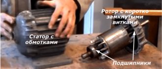
- Like all electric machines. A single-phase motor consists of 2 parts: stationary (stator) and moving (rotor).
- It is an asynchronous electric motor. on the stationary component of which there is one working winding, connected to a single-phase alternating current source.
The strengths of this type of engine include the simplicity of the design, which is a rotor with a squirrel-cage winding. The disadvantages are low starting torque and efficiency.
The main disadvantage of single-phase current is its inability to generate a magnetic field that performs rotation. Therefore, a single-phase electric motor will not start on its own when connected to the network.
In the theory of electrical machines, the rule applies: in order for a magnetic field to arise that rotates the rotor, there must be at least 2 windings (phases) on the stator. It is also required to shift one winding by a certain angle relative to the other.
During operation, alternating electric fields flow around the windings:
- According to this. The so-called starting winding is located on the stationary section of the single-phase motor. It is shifted 90 degrees relative to the working winding.
- A current shift can be obtained by including a phase-shifting link in the circuit. Active resistors, inductors and capacitors can be used for this.
- 2212 electrical steel is used as the basis for the stator and rotor.
It is incorrect to call single-phase electric motors that are 2- and 3-phase in structure, but are connected to a single-phase power source through matching circuits (capacitor electric motors). Both phases of such devices are working and are turned on all the time.
Design features
If we compare a single-phase electric motor with other electric machines, then structurally it also consists of a movable and stationary element - a stator and a rotor. The stator, due to the flow of electric current through its windings, creates a magnetic field that interacts with the rotor. As a result of electromagnetic interaction, the rotor is rotated.
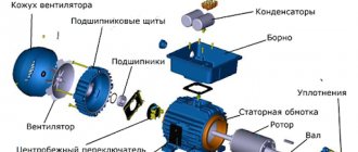
Rice. 1. Design of single-phase asynchronous electric motor
However, everything is not as simple as it might seem at first glance; if you removed the extra two windings from a conventional three-phase electric motor and plugged it into an outlet, rotation would not start. The motor simply does not have enough torque to rotate the rotor. Therefore, the design of a single-phase asynchronous electric motor has a number of features.
Rotor
The rotor of a single-phase electric motor is the same metal shaft, which is equipped with a winding. A ferromagnetic frame made of laminated steel is assembled on the shaft and grooves are made along its outer surface. Rods made of copper or aluminum are installed in the grooves on the rotor shaft, which act as a winding that conducts electric current. At the ends, the rods are connected by two rings, due to this design it is also called a squirrel cage.
When an electromagnetic flux from the stator is applied to the short-circuited windings of the rotor, current begins to flow in the squirrel cage. A ferromagnetic insert on the shaft helps to enhance the flux passing through it. However, not all models have a magnetic conductor; in some it is made of non-magnetic alloys.
Stator
The stator design in a single-phase electric motor has the same composition as in most electrical machines:
- metal case;
- a magnetic circuit made of ferromagnetic material installed inside;
- stator winding, represented by copper conductors.
The stator windings of such an electric motor are divided into two - the main winding, which is also the working winding, through which the load is constantly circulated, and the starting winding, which is activated only at the time of start-up. Both windings of a single-phase motor are located at an angle of 90° relative to each other. This design makes them similar to two-phase electric motors, which also use two windings.
But their volume, relative to the entire space of the asynchronous motor, is different; the main one is only 2/3 of the total number of slots, and the starting windings occupy 1/3.
Main types of single-phase induction motors
Household appliances and low-power devices operate on single-phase alternating current; in addition, three-phase power supply cannot be provided everywhere. Therefore, single-phase AC motors have become widespread, especially in the USA. AC motors are often preferred due to their robust design, low cost, and maintenance-free operation.
As the name suggests, a single-phase induction motor operates on the principle of induction; the same principle applies to three-phase electric motors. However, there are differences between them: single-phase electric motors, as a rule, operate at alternating current and voltage 110 -240 V, the stator field of these motors does not rotate. Instead, each time the sinusoidal voltage jumps from negative to positive, the poles change.
In single-phase electric motors, the stator field is constantly aligned in one direction, and the poles change their position once in each cycle. This means that a single-phase induction motor cannot be started on its own.
In theory, a single-phase electric motor could be started by mechanically rotating the motor and then immediately applying power. However, in practice, all electric motors start automatically.
There are four main types of electric motors:
• induction motor with capacitor start / winding operation (inductance) (CSIR),
• induction motor with capacitor start/capacitor operation (CSCR),
• rheostatic starting induction motor (RSIR) and
• permanent split capacitance (PSC) motor.
The figure below shows typical torque/speed curves for the four main types of single-phase AC motors.
Engine operating principle
ATTENTION: It is known that for the operation of any motor that operates due to electricity, be it a motor using alternating current or direct current, two magnetic fluxes are needed. The interaction between these currents provides the required torque, which is the desired parameter for any rotating motor.
When single-phase alternating current arrives at the stator winding of the motor, the alternating current begins to flow through the stator or main winding. This alternating current produces an alternating magnetic flux, which is called the main magnetic flux.
This thread is also connected to the rotor conductors and therefore cuts off these conductors. According to Faraday's law of electromagnetic induction, an electromotive force arises in the rotor. Since the rotor circuit is closed, electric current starts flowing into the rotor.
This current is called rotor current. This current produces its own magnetic flux, which is called rotor flux. Since this flux begins to be produced according to the principle of induction, a motor operating on this principle is called an induction motor. Now there are two magnetic fluxes, one of them is the main one, and the other is called the rotor magnetic flux. These two magnetic fluxes produce the desired torque that the motor requires to rotate.
How to connect a 220V asynchronous motor
Since the supply voltages for different consumers may differ from each other, there is a need to reconnect electrical equipment. Making the connection of a 220-volt asynchronous motor safe for further operation of the equipment is quite simple if you follow the proposed instructions.
In fact, this is not an impossible task. In short, all we need is to connect the windings correctly. There are two main types of asynchronous motors: three-phase with a star-delta winding, and motors with a starting winding (single-phase). The latter are used, for example, in Soviet-designed washing machines. Their model is AVE-071-4C. Let's look at each option in turn.
- Three-phase
- Switch to desired voltage Increase voltage
- Voltage reduction
General concepts
An asynchronous motor 220 volts, single-phase, requires alternating electric current; the network for connecting such a unit must be single-phase. Single-phase 220 V motors operate at a network voltage of 220 volts and a frequency of 50 hertz. These electrical values are maintained in all household electrical networks, in houses, apartments, dachas, cottages throughout Russia, and in the USA the voltage in the household electrical network is 110 volts. In production in our country, the mains voltage is single-phase, three-phase, and other types of electrical networks.
Connection diagrams
For those who are a little unfamiliar with how asynchronous electric motors are connected to a three-phase network, I strongly recommend that you read my article Connecting a motor via a magnetic contactor. I assume that the reader knows how the electric motor turns on, why and what kind of motor protection is needed, so in this article I omit these questions.
In theory everything is simple, but in practice you have to rack your brains.
Obviously, turning on the Dahlander motor windings can be done in two ways - through a switch and through contactors.
Changing speeds using a switch
Let's first consider a simpler circuit - through a PKP-25-2 type switch. Moreover, these are the only schematic diagrams that I have come across.
The switch must have three positions, one of which (middle) corresponds to the engine being turned off. About the switch device - a little later.
Connecting a two-speed motor. Diagram on the control panel switch.
Crosses on the dotted lines of the SA1 switch position indicate the closed states of the contacts. That is, in position 1, power from L1, L2, L3 is supplied to the triangle (pins U1, V1, W1). Pins U2, V2, W2 remain unconnected. The engine rotates at the first, reduced speed.
When SA1 is switched to position 2, the pins U1, V1, W1 are connected to each other, and power is supplied to U2, V2, W2.
Switching speeds using contactors
When started using contactors, the circuit will look similar:
Scheme of switching on the motor at different speeds using contactors
Here, the motor turns on the contactor KM1 at the first speed, and KM2 at the second speed. It is obvious that physically KM2 must consist of two contactors, since it is necessary to close five power contacts at once.
Operating principle and startup scheme
The reason that limits the starting winding being energized.
The resistance is lower - we found the main winding connected to the volt network without a capacitor.
The reason that limits the starting winding being energized.
The output of the other brush must be connected to one output of the stator using a jumper. To exclude an interturn short circuit, a thermal relay is used, which, when a critical temperature is reached, turns off the additional winding. Checking the functionality How to check the performance of the engine by visual inspection?
Connecting a single-phase asynchronous motor
To accelerate an asynchronous motor, it is necessary to create a rotating magnetic field. This is easily handled by a three-phase power supply, where the phases are shifted relative to each other by 120 degrees. But if we are talking about how to connect a single-phase electric motor, then a problem arises: without a phase shift, the shaft will not begin to rotate.
Inside a single-phase asynchronous motor there are two windings: starting and working. If a phase shift is provided in them, the magnetic field will become rotating. And this is the main condition for starting the electric motor. The phases can be shifted by adding resistance (resistor) or an inductive coil. But the most commonly used capacitors are starting and/or running capacitors.
With starting capacity
In most cases, the circuit only includes a starting capacitor. It is active only when the engine is starting. Therefore, the method is good when the launch promises to be difficult, otherwise the shaft will not be able to accelerate due to the small initial torque. After acceleration, the starting capacitor is turned off and operation continues without it.
The connection diagram for a motor with an auxiliary tank is shown in the figure above. To implement it, you will need a relay or at least one button, which you will press for 3 seconds while starting the motor. The auxiliary capacitor, together with the auxiliary winding, is included in the circuit only for a while.
This arrangement provides optimal starting torque if minor AC surges occur during startup. But there is also a drawback - when operating in nominal mode, the technical characteristics drop. This is due to the shape of the magnetic field of the working winding: it is oval, not circular.
With working capacity
If the start is easy, but the work is hard, then instead of a starting capacitor you will need a working capacitor. The connection diagram is shown below. The peculiarity is that the working capacitance, together with the working winding, is constantly connected to the circuit.
The circuit provides good performance when operating in nominal mode.
With both capacitors
A compromise solution is to use auxiliary and working tanks simultaneously. This method is ideal if the AC motor is already started with a load, and the work itself is difficult for it. Look, the diagram below is like two diagrams (with working and auxiliary capacitance) superimposed on each other. When starting, the trigger will be turned on for a few seconds, and the second drive will be active all the time: from start to shutdown.
Capacity calculation
The greatest difficulty for beginners is calculating the capacitance of capacitors. Professionals select them empirically, listening to the engine during startup and operation. This is how they determine whether the drive is suitable or whether they need to look for another one. But with a small error in most cases, the capacity can be calculated as follows:
- For a working drive: 0.7-0.8 µF per 1000 watts of electric motor power;
- For the starting capacitor: 2.5 times more.
Example: you have a 2 kW asynchronous single-phase electric motor. This is 2000 watts. This means that when connecting with a working capacitance, you need to stock up on a 1.4-1.6 µF drive. For the starting one you will need 3.5-4 uF.
Advantages and disadvantages of a two-phase motor
Among the advantages of a two-phase motor it is worth highlighting:
- simplicity of design. Due to the small number of elements, asynchronous two-phase motors reduce assembly costs. Therefore, in comparison with engines of similar power, they will be significantly cheaper. Also, the absence of complex elements increases the reliability of the design, and in the event of a breakdown, it will be much easier to repair;
- characteristics. The power and efficiency factors of all asynchronous motors, including two-phase ones, are at a very high level. Such motors will be more powerful compared to analogues in the same price category. Also, the rigid mechanical characteristic does not allow large differences in speeds during load fluctuations - they remain at the same level regardless of such jumps;
- power. Asynchronous two-phase motors have high values of permissible and starting torque on the shaft. This allows you to quickly accelerate the engine to its maximum values without wasting time;
- exploitation. As mentioned above, the design of electric motors with a two-phase connection is very simple and does not have many individual elements. Thus, maintenance of such devices is much easier, and the likelihood of breakdown is lower. With timely cleaning of dust and tightening of connection contacts, the engine will operate for 15 to 20 years without replacing bearings.
In general, two-phase devices are very popular due to their durability and reliability. They do not have separate collector groups, therefore they do not create additional friction and thereby reduce engine wear compared to analogues. Separate converters are not required to power the motor - just connect them to the industrial network and start it.
However, we should not forget about a number of disadvantages that prevent asynchronous motors from occupying a dominant niche in the market:
- their main problem is low starting torque. This somewhat limits the scope of application of asynchronous motors. For example, they are used in manipulators, cranes, conveyors, home and office tools where power is required instead of high starting torque;
- It is also worth noting the high reactive power they consume during startup. The fact is that despite the high performance, it is incommensurate with mechanical power, since it has no effect on it. It is worth taking this into account when calculating the energy consumption of equipment;
- You should be careful with the indicators in principle, since some system values may be lower than those required for consumption at the start of a two-phase asynchronous motor. Failure to meet the specifications will result in a significant reduction in operating efficiency and, in some cases, may result in equipment failure.
It is also worth considering how motors with a different number of phases - one, three and five - differ.
Connecting a single-phase synchronous electric motor
Despite the complexity of the design of synchronous motors, they have many advantages over asynchronous ones. The main thing is the low sensitivity to voltage surges leading to a sharp decrease or increase in current. No less significant is the fact that synchronous motors can operate even with overload, not to mention the optimal mode of reactive energy and shaft rotation at a constant speed. However, connecting is a labor-intensive process, and this is already a disadvantage.
Overclocking method
You cannot start a single-phase synchronous motor by simply applying power to its windings. Because at the moment of switching on, the direction of the supply current in the stator windings corresponds to figure (a). At this time, a pair of forces acts on the rotor, which is still at rest, which will try to rotate the shaft clockwise. But after half the period in the stator windings, the current will change its direction. Therefore, a pair of forces will already act in the opposite direction, turning the shaft counterclockwise, as in figure (b). Since the rotor has great inertia, it will never move.
To make the rotor rotate, it is necessary that it has time to make at least half a revolution so that a change in the direction of the current does not affect its rotation. This is possible if the shaft is accelerated with the help of outside forces. This can be done in two ways:
- Manually;
- Using a second engine.
Only low-power synchronous electric motors can be accelerated with your own hand strength. And for medium- and high-power units you will have to use a different motor.
When accelerating with an external force, the rotor begins to rotate at a speed close to synchronous. Then only the excitation winding turns on, and then the stator winding.
Asynchronous start of a synchronous motor
If metal rods are placed in the tips on the rotor poles, and they are connected to each other on the sides by rings, then the motor must be started asynchronously. These rods play the role of an auxiliary winding that an asynchronous motor has. In this case, the excitation winding is short-circuited using a discharge resistor, and the stator winding is connected to the network. This is the only way to achieve the same acceleration as an asynchronous electric motor. But after the rotation speed is as close as possible to synchronous (95% of it is enough), the excitation winding is connected to a direct current source. The speed becomes completely synchronous, which entails a decrease in the induced emf of the auxiliary winding down to zero. And it turns off automatically.
The layout and method of connecting your motor will depend on whether you have a synchronous or asynchronous motor. The power of the motor is also taken into account, as well as the starting method: with or without load. A basic understanding of mechanics and electromagnetic phenomena will help you understand the drawings.
Asynchronous or collector: how to distinguish
In general, you can distinguish the type of engine by a plate - a nameplate - on which its data and type are written. But this is only if it has not been repaired. After all, anything can be under the casing. So if you are not sure, it is better to determine the type yourself.
This is what a new single-phase capacitor motor looks like
How do collector motors work?
You can distinguish between asynchronous and commutator motors by their structure. The collectors must have brushes. They are located near the collector. Another mandatory attribute of this type of engine is the presence of a copper drum, divided into sections.
Such motors are produced only as single-phase ones; they are often installed in household appliances, as they allow one to obtain a large number of revolutions at the start and after acceleration. They are also convenient because they easily allow you to change the direction of rotation - you just need to change the polarity. It is also easy to organize a change in the rotation speed by changing the amplitude of the supply voltage or its cutoff angle. That is why such engines are used in most household and construction equipment.
Commutator motor structure
The disadvantages of commutator motors are high operating noise at high speeds. Remember a drill, an angle grinder, a vacuum cleaner, a washing machine, etc. The noise during their operation is decent. At low speeds, commutator motors are not so noisy (washing machine), but not all tools operate in this mode.
The second unpleasant point is that the presence of brushes and constant friction leads to the need for regular maintenance. If the current collector is not cleaned, contamination with graphite (from brushes being worn out) can cause adjacent sections in the drum to become connected and the motor simply stops working.
Basic connection diagrams
As a phase-substituting element for connecting a single-phase asynchronous motor, you can use various electromechanical elements (inductor, active resistor, etc.), but a capacitor provides the best starting effect, which is why it is used for this most often.
single phase asynchronous motor and capacitor
There are three main ways to start a single-phase asynchronous motor through:
- worker;
- launcher;
- working and starting capacitor.
In most cases, a circuit with a starting capacitor is used. This is due to the fact that it is used as a starter and only works when the engine is turned on. Further rotation of the rotor is ensured by the pulsating magnetic field of the working phase, as already described in the previous paragraph. A relay or button is often used to complete the trigger circuit.
Since the starting phase winding is used for a short time, it is not designed for heavy loads and is made of thinner wire. To prevent its failure, a thermal relay (opens the circuit after heating to the set temperature) or a centrifugal switch (turns off the starting winding after acceleration of the motor shaft) is included in the motor design.
In this way, excellent starting characteristics are achieved. However, this scheme has one significant drawback - the magnetic field inside a motor connected to a single-phase network is not circular, but elliptical. This increases losses during the conversion of electrical energy into mechanical energy and, as a result, reduces efficiency.
The circuit with a working capacitor does not provide for disconnecting the additional winding after starting and accelerating the engine. In this case, the capacitor allows you to compensate for energy losses, which leads to a natural increase in efficiency. However, in favor of efficiency, starting characteristics are sacrificed.
For the circuit to operate, it is necessary to select an element with a certain capacity, calculated taking into account the load current. An unsuitable capacitor will cause the rotating magnetic field to take on an elliptical shape.
A kind of “golden mean” is a connection diagram using both capacitors - both starting and working. When connecting the engine in this way, its starting and operating characteristics take average values relative to the circuits described above.
In practice, for devices that require the creation of a strong starting torque, the first circuit with a corresponding capacitor is used, and in the opposite situation, the second, with a working one.
Five-phase motors
Compared to the options listed above, a five-phase motor is much more similar to a two-phase one due to its design features. In most cases, a conventional one is enough for work, but a five-phase motor finds its use in cases where the system lacks resolution, acceleration and braking. In addition, it has reduced vibration and increased accuracy.
What is the difference between these motors? First of all, in the design, a 2-phase motor has eight magnetic poles, while a 5-phase motor has ten. Each of them is equipped with a winding, which leads us to the second important difference - the number of phases. As is easy to understand from the name of the motor, in a two-phase motor there are only two of them, conventionally designated as A and B. Five-phase motors have five phases at once - from A to E. Thus, while the first version of the motor operates in a strictly limited mode, the second can easily switch between different parameters, connecting phases in different combinations. This allows for wide variations in the performance, stability and intensity of the device. In fact, a five-phase motor has better characteristics in all main parameters of the device, including the driver, but in most cases they are simply not needed in the system, since standard power is sufficient for it. Thus, five-phase motors have their own strictly limited niche and are not widely used - it is worth checking the description before purchasing.
How to connect
You can connect a single-phase electric motor to a power outlet using special connectors - a plug. It is necessary to have a voltage of 220 - 240 V and a current frequency of 50 Hz. Regardless of what kind of device it is - a juicer, mixer, electric meat grinder or vacuum cleaner, the connectors of the connected electrical appliance and sockets always match!
The electric motor can be started using a capacitor of the correct capacity, connected to the starting winding, or using a resistor.
Usually all this is already provided for in the design. Just “plug the plug into the socket” and press the “start” button.
At the same time, the trigger mechanism can operate either briefly or be permanently connected to the circuit.
Thus, when choosing a purposeful “motor” for a single-phase network, it is important to start it correctly. Household appliances already have the necessary settings, just press a button
In other cases, you need to choose the right starting device so that the engine starts and performs its assigned tasks.
conclusions
Thus, asynchronous motors have carved out a strong niche in modern industry, offering many advantages at a relatively low cost of purchase and maintenance. However, it is worth noting that most systems primarily use universal three-phase motors, which can be freely converted into single-phase motors under certain system parameters.
Two-phase motors have their own niche, which they share with five-phase motors. Having different parameters and system features, they find their application in automatic devices, such as compensation or bridge systems. In addition, thanks to the ability to adjust a number of key parameters, such motors are easy to control and will heat up less. For example, it is possible to change the torque and rotation speeds through the voltage phases of the two windings. And craftsmen make such motors from a car generator.
Connection
To operate the device, 1 phase with a voltage of 220 Volts is required. This means that you can plug it into a household outlet. This is precisely the reason for the popularity of the engine among the population. All household appliances, from a juicer to a grinder, have mechanisms of this type.
connection with starting and running capacitors
There are 2 types of electric motors: with a starting winding and with a working capacitor:
- In the first type of devices. The starting winding operates via a capacitor only during start-up. Once the machine reaches normal speed, it turns off and operation continues with one winding.
- In the second case. for motors with a working capacitor, the additional winding is permanently connected through the capacitor.
An electric motor can be taken from one device and connected to another. For example, a working single-phase motor from a washing machine or vacuum cleaner can be used to operate a lawn mower, processing machine, etc.
There are 3 schemes for switching on a single-phase motor:
- In 1 scheme. The work of the starting winding is performed by means of a capacitor and only for the start-up period.
- 2 circuit also provides for a short-term connection, but it occurs through a resistance and not through a capacitor.
- Scheme 3 is the most common. In this scheme, the capacitor is constantly connected to a source of electricity, and not just during startup.
Connecting an electric motor with starting resistance:
- The auxiliary winding of such devices has increased active resistance.
- To start an electrical machine of this type, a starting resistor can be used. It should be connected in series to the starting winding. Thus, it is possible to obtain a phase shift of 30° between the winding currents, which will be quite enough to start the mechanism.
- Besides. a phase shift can be obtained by using a starting phase with a higher resistance value and a lower inductance value. This winding has fewer turns and thinner wire.
Connecting a motor with capacitor start:
- For these electric machines, the starting circuit contains a capacitor and is turned on only for the start period.
- To achieve the maximum starting torque, a circular magnetic field is required that performs the rotation. For it to occur, the winding currents must be rotated 90° relative to each other. Phase-shifting elements such as a resistor and inductor do not provide the necessary phase shift. Only the inclusion of a capacitor in the circuit allows you to obtain a phase shift of 90°, if you select the capacitance correctly.
- Calculate. Which wires belong to which winding can be determined by measuring the resistance. For the working winding, its value is always less (about 12 Ohms) than for the starting winding (usually about 30 Ohms). Accordingly, the cross-section of the working winding wire is larger than that of the starting winding.
- The capacitor is selected according to the current consumed by the motor. For example, if the current is 1.4 A, then a capacitor with a capacity of 6 μF is required.
What is the difference between three-phase motors
The operating principle of a three-phase motor is no different from a two-phase one, but the difference can be seen in the design. Instead of two magnetic fluxes, there are three of them, and they are shifted relative to each other in space and time, which allows you to create a magnetic flux rotating in the desired direction and at the desired speed.
It is worth noting that when rotating, the flow creates an EMF in the rotor conductors. As a result, the rotor continues to rotate even if the starting torque exceeds the braking torque. This phenomenon is called slip, which is, if not a key, then a very important parameter for an engine. Safety of operation depends on it, since reaching a critical level of slip reduces stability and the engine may suffer from rollover.
Thus, the principle of an asynchronous three-phase motor is based on the interaction of the rotor, which creates a magnetic field, and the currents that are present in this field. In this case, without a difference in the rotation frequencies of the fields, movement will not begin. In wide applications, unipolar three-phase motors are used in circular motors.
Operating principle
The principle of operation of an electric motor demonstrates the simplest experiment that we were all shown at school - the rotation of a frame with current in the field of a permanent magnet.
The frame with current is an analogue of the rotor, the stationary magnet is the stator. If current is applied to the frame, it will turn perpendicular to the direction of the magnetic field and freeze in this position. If you force the magnet to spin, the frame will rotate at the same speed, that is, synchronously with the magnet. We have a synchronous electric motor. But our magnet is a stator, and by definition it is motionless. How to make the magnetic field of a stationary stator rotate?
First, let's replace the permanent magnet with a current-carrying coil. This is the winding of our stator. As is known from the same school physics, a coil with current creates a magnetic field. The latter is proportional to the magnitude of the current, and the polarity depends on the direction of the current in the coil. If we apply alternating current to the coil, we get an alternating field.
A very clear analogy with a clock will help us. What vectors constantly rotate before our eyes? These are the hour hands. Let's imagine that there is a clock hanging in the corner of the room. The second hand rotates one full revolution per minute. An arrow is a vector of unit length.
The shadow that the arrow casts on the wall varies as a sine with a period of 1 minute, and the shadow cast on the floor changes as a cosine. Or a sine phase shifted by 90 degrees. But a vector is equal to the sum of its projections. In other words, the arrow is equal to the vector sum of its shadows.
What is a starting winding
Despite their name, single-phase motors have a two-phase winding: main and auxiliary, it is the latter that divides low-power electric motors into types. Thus, there are bifilar and capacitor electric motors, and if the former have a starting winding, then the latter have a starting capacitor. And if in the second type the secondary winding is in working condition all the time, then in the first it is disconnected from the network immediately after the motor reaches the required acceleration. This way the auxiliary coil is switched on for a short period of time.
Connection diagrams for single-phase asynchronous motors
With starting winding
To connect a motor with a starting winding, you will need a button in which one of the contacts opens after switching on. These opening contacts will need to be connected to the starting winding. In stores there is such a button - this is PNDS. Its middle contact closes for the holding time, and the two outer ones remain in a closed state.
Appearance of the PNVS button and the state of the contacts after the “start” button is released"
First, using measurements, we determine which winding is working and which is starting. Typically the output from the motor has three or four wires.
Consider the option with three wires. In this case, the two windings are already combined, that is, one of the wires is common. We take a tester and measure the resistance between all three pairs. The working one has the lowest resistance, the average value is the starting winding, and the highest is the common output (the resistance of two windings connected in series is measured).
If there are four pins, they ring in pairs. Find two pairs. The one with less resistance is the working one, the one with more resistance is the starting one. After this, we connect one wire from the starting and working windings, and bring out the common wire. A total of three wires remain (as in the first option):
- one from the working winding is working;
- from the starting winding;
- general.
We work further with these three wires - we use them to connect a single-phase motor.
With all these
- Connecting a single-phase motor with a starting winding via the PNVS button
connecting a single-phase motor
We connect all three wires to the button. It also has three contacts. Be sure to place the starting wire on the middle contact (which closes only during the start), the other two - on the outer ones (arbitrarily)
We connect a power cable (from 220 V) to the extreme input contacts of the PVNS, connect the middle contact with a jumper to the working one (note! not to the common one). That's the whole circuit for switching on a single-phase motor with a starting winding (bifilar) through a button
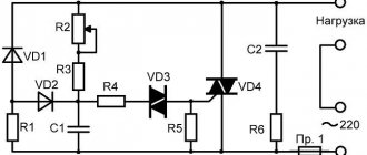
Condenser
When connecting a single-phase capacitor motor, there are options: there are three connection diagrams and all with capacitors. Without them, the engine hums, but does not start (if you connect it according to the diagram described above).
Connection diagrams for a single-phase capacitor motor
The first circuit - with a capacitor in the power supply circuit of the starting winding - starts well, but during operation the power it produces is far from rated, but much lower. The connection circuit with a capacitor in the connection circuit of the working winding gives the opposite effect: not very good performance at start-up, but good performance. Accordingly, the first circuit is used in devices with heavy starting (concrete mixers, for example), and with a working condenser - if good performance characteristics are needed.
Circuit with two capacitors
There is a third option for connecting a single-phase motor (asynchronous) - install both capacitors. It turns out something between the options described above. This scheme is implemented most often. It is in the picture above in the middle or in the photo below in more detail. When organizing this circuit, you also need a PNVS type button, which will connect the capacitor only during the start time, until the motor “accelerates”. Then two windings will remain connected, with the auxiliary winding through a capacitor.
Connecting a single-phase motor: circuit with two capacitors - working and starting
When implementing other circuits - with one capacitor - you will need a regular button, machine or toggle switch. Everything connects there simply.
Selection of capacitors
There is a rather complex formula by which you can calculate the required capacity accurately, but it is quite possible to get by with recommendations that are derived from many experiments:
- The working capacitor is taken at the rate of 70-80 uF per 1 kW of engine power;
- starting - 2-3 times more.
The operating voltage of these capacitors should be 1.5 times higher than the network voltage, that is, for a 220 volt network we take capacitors with an operating voltage of 330 V and higher. To make starting easier, look for a special capacitor for the starting circuit. They have the words Start or Starting in their markings, but you can also use regular ones.
Motor connection
The motor must be connected to a single-phase alternating voltage network of 220 volts, with a frequency of 50 hertz. These electricity ratings are available in all residential premises in our country, and as a result, single-phase motors are extremely popular. They are installed in all household appliances such as.
- Fridge.
- Vacuum cleaner.
- Juicer.
- Trimmer.
- Electric hedge trimmer.
- Sewing machine.
- Electric drill.
- Kitchen mixer.
- Fan.
- Water pump.
Types of connection
- Connection with trigger coil.
- Connection with running capacitor.
Single-phase 220 V low-power electric motors with a starting coil have a capacitor connected to the circuit during start-up. After the rotor accelerates, the coil is turned off. If the motor is made with a working capacitor, the starting circuit does not open; there is constant operation of the starting winding through the capacitor.
It is possible to use one electric motor for different purposes. The same motor can be removed from one vehicle and installed on another. A single-phase motor can be switched on in three ways.
- Electricity is temporarily switched on to the starting winding through a capacitor.
- There is a short-term voltage supply to the starting device through a resistor, without a capacitor.
- Electricity is supplied through the capacitor to the starting winding constantly, simultaneously with the operation of the working winding.
When using a resistor in the starting circuit, the winding will have a higher active resistance. There will be a phase shift sufficient to start rotation. You can use a starting winding that has higher resistance and lower inductance. In order for the winding to meet its parameters, it must have fewer turns and thinner wire.
Capacitor starting involves connecting a capacitor to the starting winding and temporarily supplying electricity. To achieve the maximum starting torque, a circular magnetic field is needed, it must perform rotation. To do this, you need to position the windings at an angle of 90 degrees. It is impossible to achieve such a shift with a resistor. If the capacitance of the capacitor is calculated correctly, it will be possible to move the windings at an angle of 90 degrees.
Wire affiliation calculation
To calculate the wires connecting the starting winding and the working winding, you need to have a device that measures ohms or a tester. It is necessary to measure the resistance of the windings. The resistance of the working winding should be less than the starting winding. For example, if measurements show 12 ohms in one winding and 30 ohms in the other, then the first of them is working, and the second is starting. The working winding will have a larger cross-section than the starting winding.
Selection of capacitor capacity
To select the capacitor capacity, you need to know how much current the electric motor consumes. If it consumes a current of 1.4 amperes, then you need a capacitor with a capacity of 6 microfarads.
Functionality check
The check should begin with a visual inspection.
- If the support of the unit was broken off, then as a result it could also work poorly.
- If the body darkens in the middle, this indicates that it has overheated excessively.
- It is possible that various foreign objects have gotten into the cut of the case; this will slow it down and contribute to overheating.
- If the bearings are dirty, overheating will occur.
- Bearing wear will cause overheating.
- If a capacitor of high capacity is connected to the 220v starting winding, it will overheat. If you suspect a capacitor, you need to disconnect it from the starting winding, turn on the motor, manually rotate the shaft, it will start and begin rotating. You need to let the engine run for about fifteen minutes, then check to see if it gets hot. If the motor did not heat up, then the reason was the increased capacitance of the capacitor. It is necessary to install a capacitor of smaller capacity.
Single-phase electric motors 220 in low power are produced in completely different models and for different purposes, and before you buy a product, you need to clearly understand what power is needed, type of fastening, number of revolutions per minute, and other characteristics.
https://youtube.com/watch?v=NW9T9xHFTuw
Capacitor calculation
It is a completely natural question about what parameters a capacitor should be used to start and operate such a device. It all depends on whether the windings on a three-phase machine are star or delta connected.
- For a star there is the following calculation: Cр = 2800•I/U.
- Triangle: Cр = 4800•I/U.
Cp is the capacity of the working capacitor in microfarads, I is the current in amperes, U is the network voltage in volts.
- The current can be calculated this way: I = P/(1.73•U•n•cos f).
P is the power of the asynchronous machine, written on its label, n is its efficiency. It is indicated there, and cos f is written next to it.
There is also a simplified calculation option. It looks like this: C = 70•Pn, where Pn is the rated power, kW (on the tag). From this formula we can conclude that for every 100 W there should be about 7 µF of capacitance.
If the capacitor capacity is too high, the windings will get very hot; if the capacitor is too low, the rotor will be difficult to spin. Therefore, the ideal option is when, after all the calculations, a kind of “adjustment” is made: the current is measured using clamps and additional capacitors are added or removed.
If you need a starting capacitor, then you need to select it so that the total capacitance (Cp + Sp) is 2-3 times higher than the working capacitance (Cp).
Connecting a phase-shifting capacitor
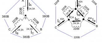
The optimal option for connecting a three-phase machine to operate from 220 volts is a triangle. So the losses will be about 30%. Two ends in the bourne go directly to the network, and a capacitor is connected between the third end and either of these two.
Such a start is possible if there is no serious load: for example, when a fan is connected. If there is a load, the rotor will either not spin at all, or the startup will take a very long time. In this case, it is worth adding a starting capacitor.
In this case, it would be good to use a switch in which one contact would close and be fixed until it is turned off, and the other would turn off when it is released. This way you can connect the starting capacitor to work for a short time. The direction of rotation is changed by switching the capacitor in the circuit to another phase.
In practice it might look like this:
The circuit for starting a three-phase motor in a single-phase circuit with a star is also simple. The losses will be greater, but sometimes there is simply no other choice.