VGA pinout - correct monitor connector pinout
VGA pinout .
The VGA monitor connector is currently the most famous and popular monitor interface, which was developed by IBM more than thirty years ago. But even despite this, the VGA video standard can be found installed on most modern computer equipment. Especially on computers where it is necessary to display video in a simplified graphic mode, with a resolution of 640x480. Absolutely all graphics cards produced in the world are compatible with this mode. The process of outputting high-resolution video information occurs exclusively after the graphics adapter drivers are loaded during the operating system startup.
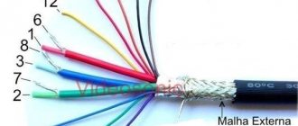
Pinout of the VGA wire according to its color coding is very helpful in some cases, for example: When performing independent testing of conductors for breaks or, if necessary, increasing the length of the wire. Note: The industry produces VGA cables with a length of about thirty meters.
A fifteen-pin VGA connector, the design of which is a trapezoid shape with pins arranged in a three-row pattern, each row having five pins. To ensure correct connection of complementary connectors, the contacts in the block are installed in an asymmetrical order. Such a device, due to its shape, guarantees correct cable connection. The numbering sequence of the output contacts should be designated as shown in the picture below:
VGA pinout according to color coding
Mini VGA connector pinout
Resoldering VGA connector
Those who own a significant amount of audio and video equipment are faced with a choice: make it yourself or purchase an adapter from the store that will convert signals of different types. Needless to say, factory devices cost a lot, but you can often do without them. And within the article we will talk about how to make a VGA to RCA adapter. Frequently asked questions will also be answered.
VGA pinout: monitor ID detection pin assignments
This monitor type detection is becoming more and more obsolete nowadays. New VGA plug-and-play monitors communicate with the computer according to VESA DDC standard.
The older VGA pinout with monitor >
ID pins set-up 4 11 12 ID2 ID0 ID1 n/cn/cn/c no monitor n/cn/c GND Mono monitor which does not support 1024×768 n/c GND n/c Color monitor which does not support 1024× 768 GND GND n/c Color monitor which supports 1024×768
GND means connected to ground n/c means that the pin is not connected anywhere
The 15-pin VGA connector was developed back in 1987 as an element of the interface between analog monitors and the graphics card of the computer system unit. The popularity of the connector is ensured by the fact that VGA mode is supported by all graphics cards. Currently, VGA is considered obsolete and is being actively replaced by digital interfaces in new graphic display devices.
What is a VGA RCA adapter
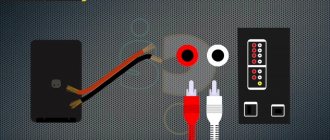
The circuit of this device may seem complicated, but only until you understand it. What is this device? This is an adapter from tulips (RCA connectors) of analog video output to VGA D-Sub for 15 pins. The device reviewed here can be used to connect a DVD player or satellite tuner to a multimedia projector. Of course, provided that it is not possible to work directly using the same type of cable, which is usually common in cheap or outdated devices.
Making your own VGA cable
If you have the raw materials, making a VGA cable and replacing a damaged connector is not a problem.
Some manufacturers refuse to comply with the standard in terms of wire layout. Therefore, before starting to manufacture a VGA cable, it is necessary to check this point according to the technical documentation.
The pinout of the VGA connector is carried out according to the diagram shown in the figure; the numbering of contacts in a row for the instrument part of the connector is done from right to left and from top to bottom. The contacts are quite convenient for soldering; after soldering, the connection point should be insulated with cambric or heat-shrink tube.
Pinout
How to pinout a 15 pin D-Sub connector? The numbers go from left to right:
1 – RY (Pr). 2 – Y. 3 – BY (Pb). 4 – Ground – Brown. 5 – Ground – WhtBrown. 6 – Ground RY (Pr) – WhtRed. 7 – Ground Y – WhtGreen. 8 – Ground BY (Pb) – WhtBlue. 9 – Not needed. 10 – Ground. 11 – Not needed. 12 – DDC DAT. 13 – Horizontal Synchronization. 14 – Vertical Synchronization. 15 – DDC Clock.
For the VGA RCA adapter cable we need six pins out of the fifteen presented. How to properly wire connectors and contacts? Check out this picture and you will understand how and what to do.
So let's see what happened. If everything was soldered correctly, then you now have an adapter that can supply a video signal to VGA D-Sub on the 15 pins of the projector. You can see approximately what the final product should look like in the photographs presented in the article.
VGA connectors pinouts
There are at least four versions of the VGA connector
, which are the three-row in and DDC2 pinouts, a less featureful and far less common, and a Mini-VGA used for laptops.
The image and below table are the newer 15-pin VGA VESA DDC2 connector
pinout.
These details will serve to illustrate a fundamental concept: conversion between two signals is not always immediate, and in some cases it may require a more expensive investment than you actually expect. In any case, we will look at audio transmission, because neither of these two types support it, so it will always be dedicated to a dedicated cable.
My personal belief is that, as much as possible, we should always avoid signal conversion. This does not detract from the fact that in some cases this approach becomes necessary, but we must definitely take into account the loss of signals. Before we continue our discussion, we need to clearly understand the differences between each of the doors that we are going to analyze. This is actually a much broader concept than a connector, but we're just interested in that last aspect.
VGA DDC2 connector pinout:
| Pin | Name | Dir | Description |
| 1 | RED | ||
| 2 | GREEN | ||
| 3 | BLUE | ||
| 4 | RES | RESERVED | |
| 5 | GND | Ground | |
| 6 | RGND | Red Ground | |
| 7 | GGND | Green Ground | |
| 8 | BGND | Blue Ground | |
| 9 | KEY | – | Key (No pin) / Optional +5V output from graphics card |
| 10 | SGND | Sync Ground | |
| 11 | ID0 | Monitor ID Bit 0 (optional) | |
| 12 | S.D.A. | I 2 C bidirectional data line | |
| 13 | HSYNC or CSYNC | ||
| 14 | VSYNC | Vertical Sync which works also as data clock | |
| 15 | SCL | I 2 C data clock in DDC2, Monitor ID3 in DDC1 |
Read also: How to sharpen knives for an electric planer
Note: Direction is Computer relative Monitor. All VGA pinout signals except R, G, B are TTL level signals.
For us, we need to know that the transmitted signal is analog. Its diagram is visible in the following figure. In this case, we distinguish three types of connectors. We won't go into the merits of the differences, just know the previous difference and the fact that singles and doubles differ in the number of pins they use and the ability to support more or less resolutions. For now we are left with a summary image of all types of these connectors.
We'll use it later for references. With that in mind, let's remember a simple concept: analog to analog signal conversion is simple, but digital triggering and analog input require additional technology. Let's return to the concept quickly expressed earlier.
The basic VGA display modes of 80×25 character mode and 640×480 in graphics mode are still supported by all modern graphic cards, independent of the extended modes supported by these cards.
VGA video specifications are:
- 256 KB Video RAM.
- 16-color and 256-color modes
- 262,144-value color palette (six bits each for red, green, and blue)
- Selectable 25.175 MHz or 28.322 MHz master clock
- Maximum of 800 horizontal pixels
- Maximum of 600 lines (Interlaced)
- Refresh rates at up to 70 Hz
- Vertical blank
- Planar mode: up to 16 colors (4 bit planes)
- Packed-pixel mode: 256 colors (Mode 13h)
- Hardware smooth scrolling support
- Some Raster Ops support
- Barrel shifter
- Split screen support
- 0.7 V peak-to-peak
- 75 ohm double-terminated impedance (18.7 mA – 13 mW)
VESA Display Data Channel is a method for integrating digital interface to VGA connector so as to enable the monitor and graphics card to communicate. The first version of the DDC standard was adopted in August 1994. It included the EDID 1.0 format and specified DDC1, DDC2B and DDC2Ab physical links. DDC version 2, introduced in 1996, split EDID into a separate standard and introduced the DDC2B+ protocol. DDC version 3, 1997, introduced the DDC2Bi protocol and support for VESA Plug and Display and Flat Panel Display Interface on separate device addresses. The DDC standard has been superseded by E-DDC in 1999. Extended display identification data (EDID) is a companion standard; it defines a compact binary file format describing the monitor’s capabilities and supported graphics modes, stored in a read-only memory (EEPROM) chip programmed by the manufacturer of the monitor.
In fact, in this type of door, the analog signal is transmitted by four pins mounted parallel to a long horizontal pin, two above it and two below it. Even so, conversion is possible with a cost-effective passive converter like this one. Please note that it is very important to have four connectors near ground.
In this case we cannot sing very easily. In this case, you know for sure that the door only has a digital signal. An item like the one shown in the photo below will never work. Converting a digital signal to an analog signal cannot be done by a passive converter such as this because an active mechanism is required. If you search for these types of converters on the most common virtual marketplaces, you will notice that these products are filled with only negative reviews, except for those who claim that the product works for them.
DDC1 allows the monitor to tell its parameters to the computer. When the VGA graphics card detects data on data-line it starts to read the data coming from the monitor synchronous to vertical sync pulse. Vertical sync pulse frequency can be increased up to 25 KHz for the time of the data transfer if a DDC1 compliant monitor is found (be sure not to send those high frequencies to non DDC1 monitors!).
DDC2 (DDC2B) allows bidirectional communication: monitor can tell its parameters and the computer can adjust monitor settings. The bidirectional data bus is a synchronous data bus similar to Access Bus and is based on I 2 C technology. The signals in the data bus are standard I 2 C signals. The computer provides 15 kohm pull-up for the SDA and SCLK lines. Monitor must provide 47 kohm pull-up on SCLK line. DDC2B bus is unidirectional and allows only one bus master – the graphics adapter. The monitor acts as a slave device at the 7-bit I²C address 50h, and provides 128-256 bytes of read-only EDID. Because this access is always a read, the first I²C octet will always be A1h.
Read also: How to connect two lamps to one wire
There are two ways to overcome this need, and they require the use of inverters. There are two types of active converters. In this case, the conversion occurs locally, and the already processed signal is output. It is currently not distributed in Italy. Such a product requires a very close investment: taking into account the five euro shipping, it arrived at my home from Germany with a total cost of thirty euros.
The same cannot be said for the other category of converters, those that are fully active, but this is a low voltage device, but it still has higher heating than the solution that has already been seen. much more and the supply is very limited, probably because many users when they see the figure go away.
E-DDC (Enhanced Display Data Channel) is the most recent revision of the DDC standard. Version 1 was introduced in 1999 and featured up to 32 Kbytes of display information storage for use by the Enhanced EDID (E-EDID) standard. E-DDC Version 1.2, approved in 2007, introduced support for DisplayPort and DisplayID standards
Examination
Wire pairs with RCA plugs soldered at the ends can be usefully compressed with heat shrink to obtain greater rigidity. In general, now you can connect the result of your work and enjoy it (if everything was soldered together as needed). Paired wires, at the ends of which RCA plugs are attached, can be crimped with heat shrink to obtain greater rigidity.
In this case, we used a satellite tuner with a 3 RCA component video output as a signal source and a Sanyo multimedia projector, which did not have a separate video input of the same type. If at the moment it is not possible to verify the functionality of the resulting adapter, then you can only carefully inspect the entire structure and make sure that there were no omissions, and everything is soldered as indicated in the article.
Making it easier
The best option is to use a VGA-RJ45 adapter without soldering, since in this case it will be enough to crimp the ends of the twisted pair with a shielded modular connector. If you have no desire to start soldering, then a pair of such adapters will cost you no more than $5. If you want to save money, or maybe you don’t have the opportunity to find such an adapter at the moment, then in this case you have only one option left - soldering.
Thus, you yourself can choose what is more convenient for you to do and how to make such an extension cord for yourself. If necessary, any types of adapters can also be soldered, one of the most popular of which is the “tulip” adapter.
What you need to understand
You should be aware that the adapter in question can ensure the operation and full functioning of a device that has a VGA video input only if it can automatically detect the type of incoming video signal. An indicator of this will be the ability to select the mode in which data will be transmitted to RGB/YPbPr. Usage will be positively impacted by sending these types of signals. Why is that?
The fact is that RGB and HV.sync (for example, data coming from the output of a personal computer’s video card) are converted to RGB, which has sync pulses in the green channel (Y). It, in turn, turns into the color-difference YPbPr. And as a result, we can conclude that these signals are not the same thing, although they can convey the same information. Therefore, carefully study what a VGA RCA adapter looks like.
VESA DDC
DDC is a specialized way to integrate a digital interface with a VGA connector and ensures a normal connection between the monitor and the video card. The first version of this standard appeared in 1994, and it included the EDID 1.0 format, defining several options for physical channels. The second version of this format, which appeared in 1996, separated EDID into a completely separate standard and also defined a new protocol, DDC2B+. A year later, a new version was released, which already introduced the updated DDC2Bi protocol, and also provided support for the VESA Plug and Display connector. Among other things, the final version included a connector for flat panel displays with separate hardware addresses.
In 1999, the DDC standard was completely replaced by E-DDC, and EDID today is nothing more than an auxiliary standard that defines the format of a compressed binary file that describes the properties, as well as graphic modes of the monitor, recorded in the memory chip by the manufacturer of this monitor.
What adapters can be made using twisted pair?
- VGA extenders are special cables that have D-Sub 15 pin connectors on both ends, while their input and output use the same technology.
- RCA (3xRCA) is used to transmit component video signals. There are three connectors at each end. Used when working with a DVD player and TV.
- RCA (D-Sub15pin) was discussed a little higher. Here are the components Y, Pr, Pb in VGA.
- To transmit analog audio, two pairs of stereo signals can be used simultaneously (4 RCA connectors at each end).
Why does TV need a computer?
Before we tell you how to connect a computer to a TV via a “tulip”, let’s answer this question. First, let's look at a regular monitor screen and take a look at the TV display. The latter, as a rule, significantly benefits from a larger diagonal and is not located somewhere in the corner on the desktop, but opposite a comfortable sofa or armchair, where it can easily fit, if not a large company, then a friend or girlfriend for sure.
Watching videos, photos and gaming - all this looks much more pleasant on a TV screen than on a modest monitor: there is no need to look at the details, use speakers, and personal PCs have not yet acquired remote controls.
The most common reason that motivates an owner to connect a TV to a computer via an RCA cable (“tulips”) is watching videos. But in fact, you can display the same picture on the LCD screen as on the monitor. And it doesn't have to be a movie. Therefore, you should not forget about photos, the Internet and games.
All kinds of car and flight simulators, arcades, shooters and even strategies feel great on the big screen, and gaming becomes truly enjoyable. Also, no one forbids you to surf the web from the comfort of your sofa.
VGA connector pinout
The pinout of the VGA interface connector is shown below. The first three pins are designed to transmit an analog signal of three primary RGB colors (1-red, 2-green and 3-blue). The red, green, and blue signal lines have their own negative wires (6, 7, and 8). Pins 13 and 14 are intended for horizontal and vertical synchronization, respectively.
The VGA connector in appearance to the COM port connector (DB9). But unlike DB9, the VGA connector has 15 pins arranged in three rows of 5 pins in each row. In addition to color rendering signals (RGB) and synchronization signals, the VGA connector also has an I2C digital interface, designed for two-way communication between the video controller and the monitor. This interface (I2C) gives VGA sufficient versatility.
It should be noted that I2C was not implemented in the first versions of the VGA standard, but was added much later with the advent of the VESA DDC2 standard. Using the I2C interface, the controller and monitor can exchange technical information, such as frequency availability and resolution, to prevent operational incompatibilities.
Wiring of cables for YUV (Y/PbCb/PrCr), VGA HD15, DVI, HDMI, s-Video, SCART (Peritel, Euroconnector) signals.
VGA HD15 connector pins
| Cont. | Signal | Description |
| 1 | RED | Channel R (red) (75 ohms, 0.7 V) |
| 2 | GREEN | Channel G (green) (75 ohms, 0.7 V) |
| 3 | BLUE | Channel B (blue) (75 ohms, 0.7 V) |
| 4 | ID2 | ID bit 2 |
| 5 | GND | Earth |
| 6 | RGND | R channel ground |
| 7 | GGND | G channel ground |
| 8 | BGND | Channel Ground B |
| 9 | KEY | No contact (key) |
| 10 | SGND | Earth Sync |
| 11 | ID0 | ID bit 0 |
| 12 | ID1 or SDA | ID bit 1 or DDC data |
| 13 | HSYNC or CSYNC | Linear or composite synchronization |
| 14 | VSYNC | Frame synchronization |
| 15 | ID3 or SCL | ID bit 3 or DDC clocks |
Wiring of cable Kramer BC5x5S (5-coaxial)
Standard connectors on other systems only have the pins needed to make the connection. The kind where if you touch two probes, it beeps to indicate the connection. Hot glue. Don't leave without it. Small, thin flathead screwdrivers, large flathead screwdriver.
- A small pair of tweezers.
- Metal pliers, tin snips, something like that.
- Soldering iron.
- Multimeter with circuit testing capability.
Okay, let's go for this sucker.
Making your own VGA cable
Insert a small, thin screwdriver into the seam shown in the photo above. Make a few more test tubes like this next to each other, then insert a large screwdriver as shown below. Screw it on and the body should float up nicely.
- Press inside and towards the label to go around the inner lip.
- As soon as you break the lip, you should hear a crack.
- You're coming in!
Then insert a large screwdriver into the seam next to the main cable and screw the housing in place.
Now you can remove the bottom part of the plastic and then pull the guts out of the top part. Kramer BC3x2T7S cable wiring (3-coaxial, presentation)
Wiring out the YUV signal (Y/PbCb/PrCr) from the VGA HD15 connector (for Kramer VP-41 4(xl), VP-419xl, VP-420, VP-421, VP-724xl, VP-728, VP-729 scalers, VP-730, VP-731, VP-725xl, VP-727, VP-747)
What are the most important factors when choosing a video cable?
Now lift the metal up and straight away from the optical audio jack and bend it to the right side as shown below.
You can now pull the bulk of the protective metal away from the rest of the socket. Remove the protective sheath free from the main cable using your metal cutters. Now you need to come across a piece of material that looks amazing, like electrical tape. Remove it and the nest should now look like the photo below. Next we need to remove the PCB from the metal. You can remove the tabs using a desoldering iron, or insert your small screwdriver under the board and lift it up as you heat the tabs with a regular iron.
DVI-I/DVI-D connector pins
| Cont. | Signal | Signal (Russian) |
| 1 | TMDS DATA 2- | TMDS data 2- |
| 2 | TMDS DATA 2+ | TMDS 2+ data |
| 3 | TMDS DATA 2/4 SHIELD | Screen for TMDS 2 and 4 data |
| 4 | TMDS DATA 4- | TMDS data 4- |
| 5 | TMDS DATA 4+ | TMDS 4+ data |
| 6 | DDC CLOCK | DDC clocks |
| 7 | DDC DATA | DDC data |
| 8 | ANALOG VERT. SYNC | Analog Frame Sync. |
| 9 | TMDS DATA 1- | TMDS data 1- |
| 10 | TMDS DATA 1+ | TMDS data 1+ |
| 11 | TMDS DATA 1/3 SHIELD | Screen for TMDS 1 and 3 data |
| 12 | TMDS DATA 3- | TMDS data 3- |
| 13 | TMDS DATA 3+ | TMDS 3+ data |
| 14 | +5V POWER | Power supply +5 V |
| 15 | GND | Earth |
| 16 | HOT PLUG DETECT | Hot Plug Sensor |
| 17 | TMDS DATA 0- | TMDS data 0- |
| 18 | TMDS DATA 0+ | TMDS data 0+ |
| 19 | TMDS DATA 0/5 SHIELD | Screen for TMDS data 0 and 5 |
| 20 | TMDS DATA 5- | TMDS data 5- |
| 21 | TMDS DATA 5+ | TMDS 5+ data |
| 22 | TMDS CLOCK SHIELD | Screen for TMDS clocks |
| 23 | TMDS CLOCK+ | TMDS+ ticks |
| 24 | TMDS CLOCK- | TMDS clocks - |
| C1 | ANALOG RED | Analog channel R |
| C2 | ANALOG GREEN | Analog channel G |
| C3 | ANALOG BLUE | Analog channel B |
| C4 | ANALOG HORZ SYNC | Analog horizontal sync. |
| C5 | ANALOG GROUND | Analog ground |
HDMI connector contacts (Single Link, Type A, up to version 1.4 inclusive)
Once the PCB is detached from the tabs, you can unplug the small connector from it and pull it out of the main unit. Finally, take a thin screwdriver and insert it between the black plastic and the thin top screen as shown below.
- Pull the metal a little and you should be able to pull the black plug out of the shielding.
- Be sure to save this piece of screen for later.
With the adhesive removed, you can remove all the wires from the plug.
Simply heat the solder on each wire until it becomes free. At this time you should put some fresh new solder on each of the pins. This will make it easier to connect new wires. The numbering may look a little strange, but it refers to how the connections are labeled on the 360 motherboard. Notice how each pin is long or short, and almost every other pin goes to ground.
| Cont. | Signal | Signal (Russian) |
| 1 | TMDS DATA 2+ | TMDS 2+ data |
| 2 | TMDS DATA 2 SHIELD | Screen for TMDS 2 data |
| 3 | TMDS DATA 2- | TMDS data 2- |
| 4 | TMDS DATA 1+ | TMDS data 1+ |
| 5 | TMDS DATA 1 SHIELD | Screen for TMDS data 1 |
| 6 | TMDS DATA 1- | TMDS data 1- |
| 7 | TMDS DATA 0+ | TMDS data 0+ |
| 8 | TMDS DATA 0 SHIELD | Screen for TMDS data 0 |
| 9 | TMDS DATA 0- | TMDS data 0- |
| 10 | TMDS CLOCK+ | TMDS+ ticks |
| 11 | TMDS CLOCK SHIELD | Screen for TMDS clocks |
| 12 | TMDS CLOCK- | TMDS clocks - |
| 13 | CEC | Consumer Electronics Control Network |
| 14 | Utility | Used for HEAC (Ethernet and Audio Return Channel) |
| 15 | DDC CLOCK | DDC clocks |
| 16 | DDC DATA | DDC data |
| 17 | DDC/CEC GND | Ground for DDC and CEC |
| 18 | +5V POWER | Power supply +5 V |
| 19 | HOT PLUG DETECT | Hot Plug Sensor |
S-Video connector pins (YC, S-VHS)
Requires purchasing multiple parts but is more useful in the long run. You'll also need left and right audio cables, as well as a yellow cable if you still like to use a composite video signal. The main connections you'll need are Red, Green, Blue, Horizontal Sync, and Vertical Sync. The selector switch has 3 wires on it. The switch can now "align" one of these two connections to establish video mode. But the new one is quite cheap and easy to use. 2 position switches if you want the box to switch modes.
- As shown at the beginning of this article.
- You only need this if you want the cable to switch modes.
- Peel off the main cover to expose the wires inside.
- They may or may not be color coded.
- Free - This saves you money on something that doesn't exist.
- This is a screw-in-screw type that is often used under the motherboard.
- Some drills.
Remove the main metal shielding to reveal the individual shielded wires inside.
Standard 4-pin MiniDIN connector
7-pin MiniDIN connector (found in ATI video cards, etc.)
10-pin connector (on ATI All-In-Wonder video cards)
| Cont. They are perfect for internal wiring of the compartment. Cut each wire to 6 inches long, now we can cut them shorter as needed. Start by sliding down some shields and stripping the end of the inner wire. Apply a little solder to it to hold all the strands together - this is called "tinning" and will make it easier to solder it to the connector. You can also put some solder at the end of the shielding to prevent it from coming off. Red Composite Video Horizontal Sync Right Audio - Shielding is not significant. Optical audio data - use a regular thin wire for this. . Step 3 - Set the ports in your notebook. When the wires are soldered to the connector, we can get a self-diagnosis box. | Signal | Description |
| 1 | C | Channel C (Color) |
| 2 | S/PDIF ground | S/PDIF Signal Ground |
| 3 | SPDIF | SPDIF signal (digital audio) |
| 4 | GND | Earth |
| 5 | GND | Earth |
| 6 | R | Audio, right channel |
| 7 | GND | Earth audio |
| 8 | Y | Channel Y (Brightness+sync) |
| 9 | V | Composite video |
| 10 | L | Audio, left channel |
10-pin connector (in Matrox G450 video cards, etc.)
Place the connector on the box lid and trace it with the tip of a knife. . Project box lid with trapezoidal connector hole. The center three pin connectors are also provided when you attach it to the main connector.
- Insert the connector through the hole and see how it fits.
- Their space is uniform.
- This way you know they will have plenty of room inside.
- Disconnect the optical audio port from the small circuit board from the connector.
Business end of the optical audio port.
Drill a hole between the optical port and the audio ports that will match the selector switch shaft. Place the pieces of the box together as shown in the picture and start by connecting the optical port. Mix the halves together, arranging the wires as you go to make sure everything fits. Once you enter the "Control Panel", go to the "System Blade" and click on "Console Settings" and "Display". Now you can select the resolution and aspect ratio according to your screen. 360 works best with widescreen displays, although you can still get it to work with square monitors. Oddly enough, it will write to the game while the toolbar and message bars take up the entire screen. Strange, right?
- Of course, be careful not to cover the 3 pins of the switch.
- Cut the wires as short as possible so it's easy to fit everything into the box.
- Wrap the case - you're done!
- If not, go to the Troubleshooting section.
You've followed all the instructions, but something isn't quite right - is it by chance one of the following?
| Cont. | Signal | Description |
| 1 | C (s-video) | Channel C (Color) |
| 2 | GND | Earth |
| 3 | Y | Channel Y (Brightness+sync) |
| 4 | RGB switching control | Control signal |
| 5 | Composite sync | Composite sync output |
| 6 | GND | Earth |
| 7 | V | Composite video |
| 8 | L | Audio, left channel |
| 9 | GND | Earth |
| 10 | R | Audio, right channel |
SCART connector pins (Peritel, Euroconnector)
Mini VGA connector pinout
Now we bet you're very glad you haven't hit all the connections in the hot bite yet - right? If you see some imagery on the screen, you probably don't have enough shielding. Make sure you have ground, 5V pins and data connected to the connector correctly.
- Check that pins 20 and 24 are connected correctly.
- Andy Warhol's inverted colors.
- Make sure all screens are connected to ground somewhere.
Depending on the signal condition, sometimes it may work, sometimes it may not.
| Cont. | Signal | Description | Level | |
| 1 | AOR | Audio output, right | 0.5 V rms | |
| 2 | AIR | Audio input, right | 0.5 V rms | >10 kOhm |
| 3 | AOL | Audio output, left + mono | 0.5 V rms | |
| 4 | AGND | Audio Ground | ||
| 5 | B GND | Ground for RGB Blue | ||
| 6 | AIL | Audio input, left + mono | 0.5 V rms | >10 kOhm |
| 7 | B | RGB Blue input | 0.7 V | 75 Ohm |
| 8 | SWTCH | Input, switching TV mode, depending on the type of TV - Audio/RGB/16:9, sometimes turning on AUX (old TVs) | 10-12 V | |
| 9 | G GND | Earth RGB Green | ||
| 10 | CLKOUT | Data 2: Clockpulse Out, only in older VCRs | ||
| 11 | G | RGB Green input | 0.7 V | 75 Ohm |
| 12 | DATA | Data 1: data output | ||
| 13 | R GND | Earth RGB Red | ||
| 14 | DATAGND | Ground for Data, remote control, only in older VCRs | ||
| 15 | R | RGB Red Input or Channel C Input | R: 0.7 V; C: 0.3 V | 75 Ohm |
| 16 | BLNK | Blanking Signal input, TV mode switching (composite/RGB), “fast” signal (new TVs) | RGB=1-3 V; Comp=0-0.4 V | 75 Ohm |
| 17 | VGND | The land of composite video | ||
| 18 | BLNKGND | Ground Blanking Signal (for pin 8 or 16) | ||
| 19 | VOUT | Composite video output | 1 V | 75 Ohm |
| 20 | VIN | Composite video input or Y (luminance) channel | 1 V | 75 Ohm |
| 21 | S.H.I.E.L.D. | Protective screen/housing |
| Prev. |
VGA and DVI connectors are used to transmit video images to digital devices, usually a video card-monitor; recently they have also become widespread in laptops for connecting to external monitors or TVs, as well as in complex medical systems.
A reliable solution is to loop the handshake lines when they are not in use. We have specifically chosen to use a personal computer as the reference frame for the signals on this page. Specific requirements for different equipment may vary.
VGA connector pinout
The first thing to remember is that there are two possibilities that you are trying to combine will actually work if you can install the cable correctly. If you have another way to prove this - for example, by trying each of the devices on a different system - do it.
| DVI pinout |
DVI is an interface standard and a corresponding connector used to transmit video images to digital display devices such as LCD monitors, televisions and projectors.
Since the signal transmitted via a DVI cable is digital and does not require double conversion, the maximum length of the cable used should not exceed 5 meters.
Before turning on both devices, turn off one of them. Then disconnect the connected device and connect the disconnected cable without otherwise rearranging the cables. Typically other cabling problems are related to communication lines. Our core business is the design of industrial electronics - most of which are sequentially controlled or networked.
To display information on the monitor, your computer sends a signal to the monitor. The signal can be in analog or digital format. However, computers operate in the digital world. The computer and video adapter convert digital data into analog format. A video adapter is an expansion card or component that provides the ability to convert displayed information into a signal that is sent to the monitor. It can also be called a graphics adapter, video card, or graphics card.
The DVI video interface can be of two types: 24-pin and 29-pin.
DVI-D 24-pin is designed for a digital interface. Its pins receive only a digital code
DVI-I 29-pin connector also supports analog signal transmission
The VGA connector is an outdated analog interface, developed in 1987 and intended for connecting analog monitors, but is still used today.
The cable connects on the back of the computer to an analog connector with 15 pins in three rows. On a regular TV, all these signals are combined into one composite video signal. There is no need to convert data from digital information to analog information. However, analog signal processing technology has improved over the years, and the difference in quality is now minimal.
The transmitter on the video adapter sends digital information to the receiver on the monitor. This gives you the option to connect a monitor that accepts a digital input or an analog input. If your video adapter only has an analog connection, find a monitor that supports analog.
VGA - Transmits three signals: chrominance, luminance, and sync. Its pinout and purpose of each pin:
Knowing the pinout of these connectors, you can easily solder a DVI-VGA or VGA-DVI adapter.
Composite video input/output (RCA), this is an analog video input-output, is widely used in video equipment as a universal means of switching. Often called "Asian" or "Tulip". Almost two separate coaxial connectors, they can be seen on the back of almost any VCR, TV, DVD player. The standard is purely analog and transmits a standard composite video signal. The main advantage of the interface is its simplicity and low cost. Color and brightness signals are transmitted over a single wire. This does not allow achieving a very clear image, so the actual resolution is around 250 -280 lines. The maximum cable length can be 20-30 meters.
The adapter can be made with male or female connectors and can stretch up to 50 feet. The second pin is attached to the green wire, and the third is used for the blue one. Pins 6, 7 and 8 act as the ground of each color channel and should be connected to the orange, green and blue striped color wires respectively.
The functions of pins in electrical connectors, whether power or signal related, must be specified in order for the connectors to be interchangeable. When connected, each pin of a connector must be in contact with a pin of another connector that has the same function. If pins of disparate functions are allowed to come into contact, the connection may fail and damage may occur.
These connectors may be present in a PC on a video card or an internal TV tuner board for receiving and transmitting an analog signal, for sending a picture to the screen of a regular TV, for recording the generated video signal to a VCR, for transmitting a signal from an analog video source to a video capture card.
S-Video (or S-VHS), another analog connector now widely used in video equipment. The chrominance and brightness signals travel through separate wires and do not interfere with each other at all. Therefore, an image with a resolution of 400-500 lines can be obtained
How to make an adapter from vga to tulip | Computers and components | OnDevices.ru
As you remember, image quality, both on modern TVs and computers, is steadily increasing. This forces manufacturers to develop new, faster interfaces. Another thing is that this change does not make it any easier for users - let’s try to look at how to make adapters from vga to tulip.
Content
What you need
- Money;
- Going to the store.
Instructions
Let's not torment each other with expectations and hide the truth.
There are no adapters from vga to tulip. The word “adapter” in the language of electronics implies a passive device - a certain number of conductors connected according to certain parameters. They simply transmit a signal in the form of charged particles. In the case of completely different connectors and protocols, this solution is not suitable at all.
Yes, there are tons of articles on the Internet about how to make a vga to tulip adapter with your own hands and even with pin routing, but remember - the grain of truth here is more than microscopic. By making such a device, you will not only get something unclear and completely non-functional, but you also risk bringing down the ports of your PC and TV. Believe me, (responding to the reader’s e-mail) it is much easier to restore a laptop battery with your own hands than to complete this task.
1. The diagram shown below appears to be incredibly popular on the Internet. However, the pins of the vga connectors have nothing to do with the explanations given to the right of the image.
2. The only chance to get something working, subject to a thousand and one details, you will only get if you use an incredibly old video card. One of these may be Matrox Millenium II . Even if you find this product among oldfags, we doubt that you will connect it to a modern computer. Windows xp 64bit, windows 7, windows 8, linux – forget, this product does not support such operating systems in hardware.
3. A ready-made adapter will save you from all the horrors mentioned above. Its price of $10-20 should not scare you away, because even in our countries this money is clearly not huge.
Here it is, in all its glory.
Swollen capacitors
These are, of course, electrolytic capacitors in the power supply filter.
This is one of the most common failures of LCD monitors. Capacitors are easily and simply soldered. Sometimes boards have a non-standard capacitor rating, for example 680 or 820 uF x 25 volts. If you encounter swollen capacitors of the same value and they are not in your radio store, do not rush to go around all the radio stores in your city in search of exactly the same value. This is exactly the case when “too much is not harmful.” Any electronics engineer will tell you this. Feel free to set 1000 uF x 25 volts and everything will work fine. It's possible even more.
Due to the fact that the power supply emits heat during operation, which has a detrimental effect on the service life of the capacitors, be sure to install capacitors marked “105C” on the case. Also, after soldering the capacitors, it would not hurt to check the fuse of the secondary circuits, which is often a simple SMD resistor with zero resistance, size 0805, located on the back of the board on the trace side.
Zener diode failure
And one more nuance, at the output of the power supply, in front of the power connector going to the scaler, an SMD zener diode is often installed
If the voltage on it exceeds the rated value, it goes into a short circuit and thereby turns off our monitor through the protection circuits. You can replace it with any suitable voltage rating. Can even be used with leads
After everything is done and repaired, we check the voltage at the power connector that goes to the scaler with a multimeter. All voltages are signed there. We make sure that they coincide with the multimeter readings.
VGA (9 pin)
1. Red video. 2. Green video. 3. Blue video. 4. Horizontal synchronization. 5. Vertical synchronization. 6. Red general. 7. Green overall. 8. Blue is common. 9. General synchronization.
https://01010101.ru/kommutaciya/vga-razem-raspajka.htmlVGA connector pinout2014-08-26T19:44:58+00:00adminCommutation Almost all modern video cards use the same 15-pin VGA connector that was used in the original IBM video cards. VGA stands for Video Graphics Adapter or Video Graphics Array. There are at least four versions of the VGA connector. These are three-row fifteen-pin connector DE-15 from original video cards, which is also called mini-sub D15, and connector DDC2...adminAdministrator