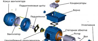
Classic connection options
Most emails Motors for modern electric drives operate from an alternating three-phase line (each of the three phases is supplied by a separate conductor). Accordingly, the terminal box contains the terminals (input and output) of three windings. They can be connected to each other and to the network using two classic schemes: “star” and “triangle”.
Star and Delta connection diagram
For the first, a characteristic feature is the closure of the end terminals of each coil to one point (in practice, this is one neutral). Meanwhile, the mains voltage is supplied to the input pins. This scheme is characterized by a softer ride, but unfortunately, it does not allow you to develop full power.
The second option with a triangle is characterized by a serial connection of the terminals of the windings: the end of the first is connected to the beginning of the second, etc. This starting option guarantees achievement of the rated power, but during switching on, large currents may arise that can thermally damage the winding terminals.
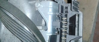
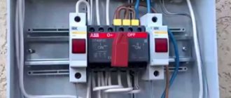
If you remove the terminal box cover, both connection options will look like this:
Conditions for connecting an electric motor
The main condition for the normal operation of three-phase motors is the stability of voltage and current in each phase of the electrical network. A break in at least one phase will result in the engine losing a significant part of its power and, when the load on the shaft exceeds 50% of the standard value, it will stop and fail. Starting in two phases is possible only in the complete absence of load and only at a time when the rotor maintains at least a small angular speed.
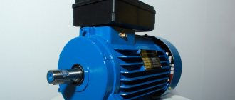
Asynchronous motor
For your information! At the moment of starting, an asynchronous motor consumes a current that is 3-5 times higher than the rated current until the rotor reaches a certain speed. This phenomenon comes from the operating principle of the engine.
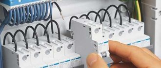
Thus, if in operating mode the motor current allows the use of conventional circuit breakers, then to ensure normal starting, switching should be done through a powerful contactor (magnetic starter).
Magnetic switch
In some cases, it is possible to connect a three-phase motor to a single-phase household network. At the same time, power characteristics drop significantly. This situation arises very often when it is necessary to use an industrial drive in a domestic environment. Using a special switching circuit, they ensure normal operation of the motor, taking into account the reduction in power.
Application of magnetic contactor
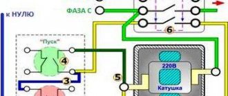
To organize a soft start, it is necessary to introduce a special switching device - a starter - into the power circuit. This is one of the connector options that can be supplemented with optional elements, for example, a thermal relay. A huge advantage of this scheme is the possibility of organizing not only the start-up of electricity. the engine, but also stopping it, reversing it, as well as protecting connections from damage by excess currents. In addition, the core or coil can have a voltage rating of 380 or 220V, which allows you to connect the motor to a power and household network.
Classic electrical circuits for connecting motors through a starter can be divided into two types:
- Irreversible. Connection of the unit and the network without the need/possibility of organizing its reverse movement. In this case, it is possible to integrate both into a power and household (220V) network,
Non-reversible connection diagram
- Reversible. An electrical circuit that combines two starters (unit) with a circuit breaker. It is also possible to change the direction of rotation of the rotor assembly for power and household (220V) networks.
Reversible connection diagram
As you can judge from the illustrations, the differences between the “network” options lie in the connection points of the contactor terminals:
- for 380 volts the contacts are closed on 2 of 3 phases,
- for 220 volts, one of the contacts is connected to the extreme phase, and the second to zero.
Thermal relay
In addition, in all four options there is an element designated as “P”. This is nothing more than a thermal relay. It is connected in series with the contactor coil and serves to protect the motor from excessive current loads.
According to the principle of operation, the thermal relay is a key, that is, when critical current values for the operation of the unit and contactor are reached, a temporary break in the power supply occurs. Some types of thermal relays or “thermal relays” are used for DC circuits or specific modes (delayed start-up, phase failure, etc.).
Constant activation of the magnetic starter leads to mechanical wear of the contacts, which a thyristor or contactless circuit does not have. The circuit is broken not mechanically (dividing the contact group), but electronically - due to diode bridges.
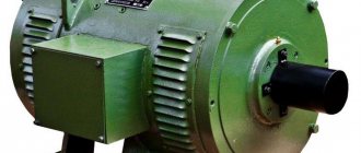
Three-phase asynchronous motor
Current is supplied to the rotor of a synchronous motor from a power source. But we know from the same school physics that a current in a coil can be created by an alternating magnetic field. You can simply short the ends of the coil to the rotor. You can even leave just one turn, like in a frame. And let the current induce a rotating magnetic field of the stator.
- At the moment of start, the rotor is stationary, and the stator field rotates.
- The field in the rotor circuit changes, inducing an electric current.
- The rotor will begin to catch up with the stator field. But it will never catch up, since in this case the current will cease to be induced in it.
- In an asynchronous motor, the rotor always rotates slower than the magnetic field.
- The difference in speed is called slip. Connecting an asynchronous motor does not require current to be supplied to the rotor winding.
Synchronous and asynchronous motors have their own advantages and disadvantages, but the fact is that the majority of motors used in industry today are three-phase asynchronous motors.
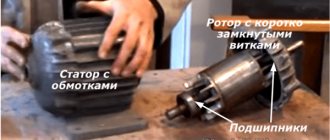
Operation of devices with a specific moving part
The usual version of the rotor assembly of a three-phase asynchronous electric motor is a short-circuited “squirrel cage” type, which is assembled from steel plates. When there is a need to reduce the rating of starting currents with the ability to regulate the rotation speed, then a wound rotor is used. Its characteristic feature is two groups of conclusions:
- Stator. Classic terminal block to which mains voltage is supplied (380 or 220V),
- Rotary. Additional terminal block for the terminals of the wound rotor windings, to which the contacts of the rheostat (resistance block) are connected.
The latter is necessary for a smooth start with gradual switching on/off of individual resistances in the wound rotor winding circuit.
Connection methods and diagrams
Depending on the type of load used for the electric motor, its design features and characteristics, and the desired result, various connection schemes can be used. Most often, capacitors are used to connect a three-phase unit as a single-phase household load, but their number and method of putting them into operation depend on many parameters. Therefore, next we will look at various options for connecting electric motors.
Without capacitors
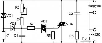
To connect an asynchronous electric motor to a 220V network, it is not at all necessary to use a capacitive element. Thanks to the development of semiconductor switches and circuits using them, you can avoid unnecessary power losses. For this, a transistor or dinistor switch is used.
Triangle capacitorless starting circuit
The above circuit is designed for starting electric motors with low speeds up to 1500 rpm and relatively low power.
The circuit works as follows:
- when voltage is applied to the input, the wires are connected to two points of the motor;
- voltage is supplied to the third point of the triangle through a timing RC circuit;
- the resistance store R1 and R2 regulates the shift interval by moving the slider;
- after the capacitor in the chain is saturated, dinistor VS1 passes a signal to open triac VS2.
If the connection of an electrical unit involves a large starting load and requires operation at high speeds - up to 3000 rpm, then it is necessary to use a similar electronic key circuit with two triacs and separate timing elements for each of them. But the windings of the electric machine will be connected according to an open star circuit. The operation of the scheme is similar to the previous one:
Capacitorless star starting circuit
With capacitors
Using capacitive elements to connect an electric motor is the most common method. For this, two capacitors are used, one of which is starting and the second is working. The starting voltage is introduced briefly, the additional capacitance allows you to increase the voltage shift in the corresponding winding and create more force.
Connection diagram with capacitors
As you can see from the figure above, a single-phase voltage is supplied to the electric motor between points L and N. The asynchronous motor IM is connected to them with two windings, and the same phase is connected to the third windings through the contacts of the push-button switch SA1 and SA2, which switch parallel-connected capacitors C1 and C2.
The asynchronous electric motor is switched on according to the following principle:
- By pressing the Start button, two pairs of contacts are set in motion - SA1 and SA2, after which electric current begins to flow in the windings;
- After the button is released, contact SA2 remains closed, supplying a biased phase through capacitor C1, and SA1 opens, removing the starting capacitor C2 from the circuit;
- The starting characteristics return to nominal and the engine operates normally.
But with this connection of an asynchronous motor to a 220V network, the rotor will rotate in only one direction. Therefore, to perform reverse movements, you will need to completely sort out the connection points or use another method.
With reverse
Some technological operations require forward and reverse rotation of the motor shaft, so the connection must change the sequence of voltage alternation on the windings. Of course, it is impractical to perform such operations manually, especially when changing direction is performed several times an hour.
Therefore, it is much more efficient to reverse the electric motor through a switch with two pairs of contacts having opposite logic. This could be a toggle switch or rotary switch included in the circuit instead of a regular button:
Switching on a three-phase motor with reverse
As you can see in the figure, the connection principle is no different from the considered circuit with a capacitor, with the only difference being that the SA switch has two stable positions. In one case, it supplies voltage to the capacitors from the phase, in the second from the neutral conductor. Therefore, the alternation of windings is reversed by simply switching the toggle switch.
Using a starter
If the electric motor creates a large starting and operating load during operation, then it is better to connect it through a magnetic starter or contactor. Which will ensure reliable switching and subsequent protection of the electrical machine from emergency situations.
Switching circuit via a magnetic starter
As you can see in the diagram, switching is carried out by pressing the Start button, which closes the starter coil control circuit and supplies voltage to the Descent starting capacitor. When current flows through the starter coil K1, its contacts K1.1 and K1.2 close. The first ones are designed to close the supply line of the electric motor. The latter bypass the Start button, which returns to the off state and opens the power supply circuit to the starting capacitor.
Operation of DPT type P 41
An electric machine, powered by 220 V DC, has a more complex design compared to the units described above. The specifics of operation, for example, of the P 41 model, require the presence of a commutator-brush assembly, an armature coil, and auxiliary stator (inductor) poles. Motors of this model size belong to machines with an electromagnetic inductor. That is, to connect and start P 41, it is not permanent magnets that are used, but an independent or mixed excitation winding of 110 or 220V.
As you can judge, the operation of three-phase (380 V) and single-phase (220 V) AC machines or DFC type P 41 can be organized in a variety of ways, from classical to specific ones, taking into account actual operating conditions.
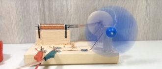
Single-phase asynchronous electric motor
If we leave a short-circuited coil on the rotor and one coil on the stator, we will get an amazing design - an asynchronous single-phase motor.
At first glance, it seems that such an engine should not work. After all, there is no current in the rotor , and the magnetic field of the stator does not rotate. But if you push the rotor by hand in any direction, the engine will start! And it will rotate in the direction in which it was pushed at launch.
The operation of this motor can be explained by imagining the stationary alternating magnetic field of the stator as the sum of two fields rotating towards each other. While the rotor is stationary, these fields balance each other, so a single-phase asynchronous motor cannot start on its own. If the rotor is set in motion by an external force, it will rotate in parallel with one vector and towards the other.
A passing vector will pull the rotor along with it, a counter vector will slow it down.
It can be shown that due to the difference between the head and tail speeds, the influence of the tail vector will be stronger, and the engine will operate in asynchronous mode.
How to connect via capacitors
First, decide which circuit is assembled on the ED. To do this, open the bar cover where the blood pressure terminals are output, and see how many wires come out of the device (most often there are six).
The designations are as follows: C1-C3 are the beginnings of the winding, and C4-C6 are its ends. If the beginnings or ends of the windings are combined with each other, this is a “star”.
The most difficult situation is if six wires simply come out of the housing. In this case, you need to look for the corresponding designations on them (C1-C6).
To implement a scheme for connecting a three-phase electric motor to a single-phase network, two types of capacitors are required - starting and working.
The first ones are used to start the electric motor at the first moment. As soon as the rotor spins to the required number of revolutions, the starting capacitance is excluded from the circuit.
If this does not happen, there may be serious consequences, including engine damage.
The main function is performed by working capacitors. Here it is worth considering the following points:
- Working capacitors are connected in parallel;
- The rated voltage must be at least 300 Volts;
- The capacity of the working capacitors is selected taking into account 7 µF per 100 W;
- It is desirable that the type of working and starting capacitor be identical. Popular options are MBGP, MPGO, KBP and others.
Connecting a single-phase motor
Before you start connecting any electric motor, you must be completely sure that the motor is working. Carry out a full inspection to check the quality of the bearings and the absence of play in the rotor seats and in the engine covers. Check the windings for short circuits between each other and the housing.
Also, when connecting, you must follow safety precautions, be extremely careful and work without haste.
To connect a single-phase electric motor with a starting winding, we need a switch with a starting contact - PNVS. The number after the letters indicates the current strength for which the switch is designed.
note
In the previous article, I told you how to determine the type of motor, whether it is three-phase or single-phase.
And if you doubt whether it is a capacitor motor or one with a starting winding, then you must first connect the motor as with a starting winding, and if it does not start, then it is a capacitor motor.
In order to find out which of the two windings is working, it is necessary to measure their resistance. The coil that has the least resistance is the working one. The exception is a very small percentage of capacitor motors, in which both the working winding and the capacitor winding are the same and have the same resistance.
The starting winding is connected only to start the engine and is turned off after the engine has picked up speed. Only the working winding remains in operation. A correctly wound engine, with an inspection carried out without load on the shaft, reaches the required speed in no more than a few seconds, but more often - instantly. Therefore, during a test run, the engine must be securely fastened.
To start a motor with a starting winding, you need to connect it according to the following diagram:
We connect one end of the working and starting ends together and connect it to one of the extreme marks of the button. This will be the common wire. We connect the second end of the working winding to the second extreme mark of the button. And we connect the remaining wire of the trigger coil to the middle mark of the button.
In this case, we use the stamps on only one side of the button. Three marks on the other side remain free for now. We connect the power cord to the outer two of them. And to the central mark we connect a jumper from the outer mark opposite which one working wire is connected.
We close the button cover, secure the motor, do a test switch on and off the button to make sure it is working and to know that it is in the off state. We plug the plug into the socket, press the start button and hold it until the engine speeds up.
Important
But no more than a few seconds. Then release the button. If the motor hums but does not start to rotate, then the motor is a capacitor motor and must be connected according to a different circuit.
To connect a capacitor motor, a start button is not needed.
Therefore, any starter, toggle switch or switch that can open and close two contacts at the same time is suitable.
We connect one end of the working and one end of the starting windings together and bring them to one of the switch marks. We connect the second ends of the windings to different terminals of the capacitor and at the same time we also connect the wire from the working coil to the second mark of the switch. We connect the power cord to the opposite marks of the switch.
We switch the toggle switch to the off position, check that the engine is securely fastened, plug the plug into the socket and turn on the toggle switch. The motor without load on the shaft should start instantly.
In order for a single-phase motor to rotate in the other direction, it is necessary to swap the leads of one of the windings.
If we need the engine to rotate in one direction or the other, then we need to install a reverse toggle switch. Moreover, place it so that we cannot switch it while the engine is running. This applies to a capacitor motor. The toggle switch should have 2 or 3 positions and have six pins.
Star-delta circuit
In domestic engines, the “star” is often already assembled, but the triangle needs to be implemented, i.e. connect three phases, and assemble a star from the remaining six ends of the winding. Below is a drawing to make it easier to understand.
The main advantage of connecting a three-phase circuit with a star is that the motor produces the most power.
Nevertheless, such a connection is loved by amateurs, but is not often used in production, since the connection diagram is complex.
For it to work you need three starters:
The stator winding is connected to the first of them, K1, on one side, and the current on the other. The remaining ends of the stator are connected to starters K2 and K3, and then to obtain a “triangle”, the winding with K2 is also connected to the phases.
Having connected to phase K3, slightly shorten the remaining ends to obtain a “star” circuit.
Important: it is unacceptable to turn on K3 and K2 at the same time, so that a short circuit does not occur, which can lead to the shutdown of the electric motor. To avoid this, electrical interlocking is used. It works like this: when one of the starters is turned on, the other is turned off, i.e. its contacts open.
How the scheme works
When K1 is turned on using a time relay, K3 is turned on. The three-phase motor, connected in a star configuration, operates with more power than usual. After some time, the contacts of relay K3 open, but K2 starts. Now the motor operation pattern is “triangle”, and its power becomes less.
When a power cut is required, K1 is started. The pattern is repeated in subsequent cycles.
A very complex connection requires skill and is not recommended for beginners.
Regulations
Taking into account the large number of electrical elements, a number of normative documents have been developed for their alphanumeric (hereinafter referred to as BO) and conventional graphic designations (UGO) to eliminate discrepancies. Below is a table showing the main standards.
Table 1. Standards for graphic designation of individual elements in installation and circuit diagrams.
| GOST number | Short description |
| 2.710 81 | This document contains GOST requirements for BO of various types of electrical elements, including electrical appliances. |
| 2.747 68 | Requirements for the dimensions of displaying elements in graphical form. |
| 21.614 88 | Accepted codes for electrical and wiring plans. |
| 2.755 87 | Display of switching devices and contact connections on diagrams |
| 2.756 76 | Standards for sensing parts of electromechanical equipment. |
| 2.709 89 | This standard regulates the standards in accordance with which contact connections and wires are indicated on diagrams. |
| 21.404 85 | Schematic symbols for equipment used in automation systems |
It should be taken into account that the element base changes over time, and accordingly changes are made to regulatory documents, although this process is more inert. Let's give a simple example: RCDs and automatic circuit breakers have been widely used in Russia for more than a decade, but there is still no single standard according to GOST 2.755-87 for these devices, unlike circuit breakers. It is quite possible that this issue will be resolved in the near future. To keep abreast of such innovations, professionals monitor changes in regulatory documents; amateurs do not have to do this; it is enough to know the decoding of the main symbols.
Electric motor connection options
Most often, connecting an electric motor at 220/380V with an existing capacitor is used, through which the power is reduced. The capacitor contact should be connected to zero, while the other should be connected to the next output of the motor. The result is a device with minimal power.
With increased power, a starting capacitor should be added to the existing circuit. When connected single-phase, it announces the third output.
As for the method of connecting an asynchronous electric motor, it is simply connected with a triangle, as well as a star. Such units have several windings. To change the existing voltage, you cannot do without swapping the outputs that go to the top of the connections.
When connecting such motors, it is important to read the instructions and certificate, since in imported versions you can often find a triangle that is suitable for domestic 220 volts. Such engines, if you are not careful about this issue and are connected with a star, immediately burn out.
With a power reaching more than 3 watts, it is not recommended to connect the motor, as this may cause a short circuit and damage the RCD.
Electric motors: design and principle of operationApplication of electric motors
- Electric motor rotor - design features and operating principle of the device. Repair and restoration instructions
Letter designations
In electrical diagrams, in addition to graphic symbols, alphabetic symbols are also used, since without the latter, reading the drawings will be quite problematic. Alphanumeric marking, just like UGO, is regulated by regulatory documents, for electrical this is GOST 7624 55. Below is a table with BO for the main components of electrical circuits.
Letter designations of main elements
Unfortunately, the size of this article does not allow us to provide all the correct graphic and letter symbols, but we have indicated regulatory documents from which all the missing information can be obtained. It should be taken into account that current standards may change depending on the modernization of the technical base, therefore, we recommend monitoring the release of new additions to regulations.