Added March 5, 2022 at 10:15 pm
Save or share
If you've ever blown up a water heater or ever tried to make submersible electronics, you know how important it is to determine if there is water around. This water level sensor makes it very easy!
This sensor can be used to measure water level, monitor a septic tank, detect rain or detect leaks.
How a water level sensor works and its interaction with Arduino
Hardware overview
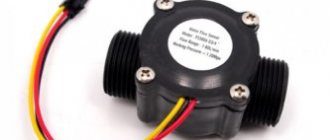
This sensor contains a series of ten open copper traces, five of which are power and five are sensitive.
These tracks are interleaved so that between every two supply tracks there is one sensing track.
Usually these paths are not connected to each other, but when immersed they are connected by water.
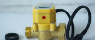
Figure 1 – Water level sensor
There is a power indicator on the board that lights up when power is applied to the board.
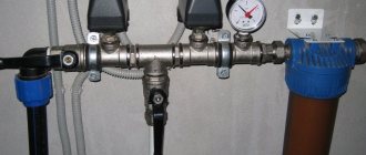
Power circuit
The power source can be made using a different transformer circuit. It is necessary that there is a constant voltage at the output of the rectifier to ensure reliable operation of the relay. For example, if a relay has a 12V winding, then the supply voltage can be lowered to 12V.
The power source, whatever it may be, must provide galvanic isolation between the electrical network and low-voltage circuits. Otherwise, it may result in electric shock. For the same reason, you cannot use key thyristor or transistor circuits with galvanic coupling with the control circuit instead of relays (only possible when controlled via an optocoupler).
How does a water level sensor work?
The operation of the water level sensor is quite simple.
A series of open parallel conductors together act as a variable resistor (potentiometer), the resistance of which changes depending on the water level.
The change in resistance corresponds to the distance from the top of the sensor to the surface of the water.
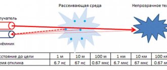
Figure 2 – Demonstration of the operation of the water level sensor
Resistance is inversely proportional to water height:
- the more water the sensor is immersed in, the better the conductivity and the lower the resistance;
- The less water in which the sensor is immersed, the worse the conductivity and the higher the resistance.
The sensor, in accordance with the resistance, produces an output voltage, by measuring which we can determine the water level.
Details
The K561LE10 chip can be replaced with a K176LE10. Zener diode on KS512, KS513. LEDs are constant light indicators (not blinking) of any type, brand and color. The KTs407 diode bridge can be replaced with almost any one or made with almost any diodes for general use.
VD2 diode is almost any low or medium power silicon diode. The KT315E transistor can be replaced with any general-purpose p-p-p transistor, for example, KT3102, KT315, MP35. Relay F40.51 can be replaced by any relay with a 24V winding, the contacts of which are suitable for the pump power. If you use a relay with a winding at a lower voltage, you need to connect a resistor in series with the winding, on which the excess will drop.
For example, with a 12V winding, the resistance of such a resistor should be equal to the DC resistance of the relay winding. If the relay winding current is more than 80 mA, you need to remake the switch on VT1 for the corresponding current, it is possible to make this cascade using a compound transistor or a power field-effect transistor.
When using a triac optocoupler instead of a relay, the optocoupler LED is turned on instead of the relay winding through a current-limiting resistor, with a resistance corresponding to the rated current through the LED of this optocoupler.
Water level sensor pinout
This water level sensor is very easy to use and has only 3 pins for connection.
Figure 3 – Pinout of the water level sensor
The S (Signal) pin is an analog output that will be connected to one of the analog inputs of your Arduino board.
The + (VCC) pin provides power to the sensor. It is recommended to power the sensor with a voltage of 3.3 to 5 V. Please note that the voltage at the analog output will depend on what supply voltage is supplied to the sensor.
— (GND) – ground.
Instructions (operating manual) for level control relay PZ-818
Instructions for level control relay, page 1
Instructions for level control relay, page 2
Instructions for level control relay, page 3
The manual can be downloaded as a PDF file from the manufacturer's website.
A little later I will post information on installing this level control relay in a real system.
Thank you for your attention, I welcome questions in the comments!
Connecting a water level sensor with Arduino
Let's connect the water level sensor to Arduino.
First you need to apply power to the sensor. To do this, you can connect the +(VCC) pin on the module to the 5V pin on the Arduino, and the -(GND) pin of the module to the GND pin of the Arduino.
However, one of the well-known problems with these sensors is their short lifespan when exposed to humid environments. By continuously supplying power to the probe, the corrosion rate increases significantly.
To overcome this problem, we recommend not constantly powering the sensor, but only turning it on when you are taking readings.
The easiest way to do this is to connect the VCC pin to the Arduino digital pin and set it to high or low when needed. So let's connect the VCC pin of the module to digital pin 7 of the Arduino.
Finally, connect the S (Signal) pin to the A0 pin of the Arduino A/D converter.
The connection diagram is shown in the following figure.
Figure 4 – Connection diagram of the water level sensor to Arduino
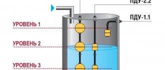
Schemes with work at one level
The instructions also provide filling and pumping diagrams with operation at one level. The inputs of the Min and Max sensors are closed there, and instead of three sensors, two are used.
The “single-level” filling scheme works “clumsily” - as soon as the sensor is exposed, after a delay the pump turns on until the water again touches both sensors.
The circuit for pumping operation is the same, with the installation of a jumper. Only the sensors are installed near the bottom of the tank.
And finally -
Basic example of water level detection
Once the circuit is assembled, upload the following sketch to the Arduino.
// Pins connected to the sensor #define sensorPower 7 #define sensorPin A0 // Variable for storing the water level value int val = 0; void setup() { // Set up D7 for output pinMode(sensorPower, OUTPUT); // Set the level low so that no power is supplied to the sensor digitalWrite(sensorPower, LOW); Serial.begin(9600); } void loop() { // get the reading from the function below and print it int level = readSensor(); Serial.print("Water level: "); Serial.println(level); delay(1000); } // This function is used to get readings int readSensor() { digitalWrite(sensorPower, HIGH); // Enable sensor delay(10); // Wait 10 milliseconds int val = analogRead(sensorPin); // Read the analog value from the sensor digitalWrite(sensorPower, LOW); // Turn off the sensor return val; // Return current reading }
Once the sketch is uploaded, open the serial port monitor window to see the Arduino output. You should see a value of 0 when the sensor is not touching anything. To see how water is detected, you can take a glass of water and slowly immerse the sensor in it.
Figure 5 – Displaying water level sensor readings
The sensor is not designed to be fully immersed, so be careful when experimenting to ensure that only the exposed traces on the circuit board come into contact with water.
Explanation
The sketch begins by declaring the Arduino pins to which the + (VCC) and S (signal) pins of the sensor are connected.
#define sensorPower 7 #define sensorPin A0
Next, we define the variable val, which stores the current value of the water level.
int val = 0;
Now in the setup() function we first configure the pin to power the sensor as an output and then set it to a low logic level so that no power is supplied to the sensor initially. We also set up serial communication with the computer.
pinMode(sensorPower, OUTPUT); digitalWrite(sensorPower, LOW); Serial.begin(9600);
In the loop() function, we periodically call the readSensor() function at one second intervals and print the return value.
int level = readSensor(); Serial.print("Water level: "); Serial.println(level); delay(1000);
The readSensor() function is used to get the current water level. It turns on the sensor, waits 10 milliseconds, reads the analog value from the sensor, turns off the sensor, and then returns the analog value.
int readSensor() { digitalWrite(sensorPower, HIGH); // Enable sensor delay(10); // Wait 10 milliseconds int val = analogRead(sensorPin); // Read the analog value from the sensor digitalWrite(sensorPower, LOW); // Turn off the sensor return val; // Return current reading }
↑ Sensor installation
I installed the sensor in the housing of a Christmas tree garland.
The housing was secured to the tank lid.
Drilled holes to install the sensor.
I soldered the cable, electrolytic capacitor and filled everything with hot glue.
Calibration
To get accurate readings from your water level sensor, it is recommended that you first calibrate it for the specific type of water you plan to monitor.
As you know, pure water does not conduct electricity. In fact, it is minerals and impurities that make it conductive. So your sensor may be more or less sensitive depending on the type of water you use.
Before you start monitoring data or running any event handlers, you need to see what readings you're actually getting from your sensor.
Using the sketch above, note what values your sensor produces when it is completely dry, when it is partially submerged, and when it is completely submerged.
For example, using the same circuit as above, you will see values similar to the following in the serial port monitor:
- when sensor is dry: 0;
- when it is partially immersed in water: ~420;
- when it is completely immersed: ~520.
Figure 6 - Water Level Sensor Calibration
This test may require some trial and error. Once you have good control over these readings, you can use them as thresholds if you intend to initiate any action. In the next example, we're going to do just that.
Test results and real work
Testing has found that there are no false alarms, even when installed inside a small transparent water tank in bright daylight. If you immerse the tip of the sensor (the clear prism) in water, it works as expected.
In general, this optical level sensor has no moving parts and is ideal for measuring extreme water levels. It produces an output signal that can indicate the presence or absence of liquid. A compact and inexpensive optical liquid level sensor like this is a good choice, especially where measurement accuracy is not important.
Water level determination project
For our next example, we're going to create a portable water level sensor that will light up LEDs based on the water level.
Connection diagram
We will use the diagram from the previous example. But this time we just need to add some LEDs.
Connect three LEDs to digital pins 2, 3 and 4 via 220 ohm current limiting resistors.
Assemble the circuit as shown below:
Figure 7 – Water level indication using LEDs
Arduino code
Once the circuit is assembled, upload the following sketch to the Arduino.
In this sketch, two variables are declared, namely lowerThreshold and upperThreshold. These variables represent our threshold levels.
Anything below the lower threshold turns on the red LED. Anything above the upper threshold turns on the green LED. Everything in between turns on the yellow LED.
/* Change these values based on your calibration values */ int lowerThreshold = 420; int upperThreshold = 520; // Pins connected to the sensor #define sensorPower 7 #define sensorPin A0 // Variable for storing the water level value int val = 0; //Declare the pins to which the LEDs are connected int redLED = 2; int yellowLED = 3; int greenLED = 4; void setup() { Serial.begin(9600); pinMode(sensorPower, OUTPUT); digitalWrite(sensorPower, LOW); // Configure the LED pins to output pinMode(redLED, OUTPUT); pinMode(yellowLED, OUTPUT); pinMode(greenLED, OUTPUT); // Initially turn off all LEDs digitalWrite(redLED, LOW); digitalWrite(yellowLED, LOW); digitalWrite(greenLED, LOW); } void loop() { int level = readSensor(); if (level == 0) { Serial.println("Water Level: Empty"); digitalWrite(redLED, LOW); digitalWrite(yellowLED, LOW); digitalWrite(greenLED, LOW); } else if (level > 0 && level <= lowerThreshold) { Serial.println("Water Level: Low"); digitalWrite(redLED, HIGH); digitalWrite(yellowLED, LOW); digitalWrite(greenLED, LOW); } else if (level > lowerThreshold && level <= upperThreshold) { Serial.println("Water Level: Medium"); digitalWrite(redLED, LOW); digitalWrite(yellowLED, HIGH); digitalWrite(greenLED, LOW); } else if (level > upperThreshold) { Serial.println("Water Level: High"); digitalWrite(redLED, LOW); digitalWrite(yellowLED, LOW); digitalWrite(greenLED, HIGH); } delay(1000); } // This function is used to get readings int readSensor() { digitalWrite(sensorPower, HIGH); delay(10); val = analogRead(sensorPin); digitalWrite(sensorPower, LOW); return val; }
Original article:
- How Water Level Sensor Works and Interface it with Arduino
LiveInternetLiveInternet
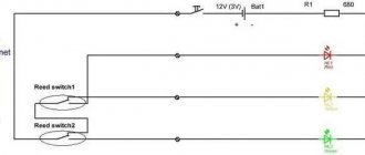
Do-it-yourself water level controller in the tank There are situations when it is necessary to control the water level. For example, when water accumulates in the cellar (or a hole in the garage) and it is needed Do-it-yourself water level controller in the tank
There are situations when it is necessary to control the water level. For example, when water accumulates in a cellar (or a hole in the garage) and needs to be pumped out in a timely manner. Or when drawing a large volume of water from a well (well), it is very important to determine in time that the water has run out and you need to turn off the pump until the water reaches the required level again. In these and similar cases, a water level switch will help us.
Case dimensions: 63.3x45x28mm
We screw the wires of the humidity sensor to the green terminal block
The area of the contact pads of the humidity sensor is at least 1 sq. cm (can be cut from a tin can)
Relay contacts are routed to the blue terminal block
If we are pumping water from a metal barrel or other conductive reservoir, then electrode 1 is not needed; we connect the barrel itself instead:
the water has reached the upper level - the pump has turned on (the relay contacts have closed)
the water has dropped to the lower level - the pump has turned off (the relay contacts have opened)
It is possible to use this relay as a leak detector - if you need to use a powerful siren bell or other powerful device as an alarm. In this case, connect contacts 2-3 on the green terminal block. It will not be possible to use grounded structures of the room to connect the second wire, because The relay inputs are galvanically isolated from the mains.
Load capacity of relay contacts: 1A
Important:
the starting current of almost any pump exceeds the rated current by 5-10 times. For example, a 250 W pump has a rated current I (A) = P (W) / U (V); 250/220=1.136A, respectively, the starting current can be up to 11.36A. To turn on such a pump, a thyristor relay
. Example: electrodes made of tin from a tin can are fixed with M4 screws on a piece of plexiglass.
Electrode dimensions 30x40 mm
Connection for using the relay as a leak detector in the basement of a house.
It differs from option 1 in the opposite operating algorithm:
the water has reached the upper level - the pump has turned off (the relay contacts have opened)
the water dropped to the lower level - the pump turned on (relay contacts closed)
This option is advisable to use for filling various containers with water. For example, a barrel for a summer shower or watering a garden. A pump (together with a relay option 1) or an electromagnetic water valve can be connected as an actuator if there is a stationary water supply. It is possible to use this option for automatic watering in greenhouses, gardens, etc.
Connection diagram of a pump through a thyristor relay for pumping water from a well (well) into a storage tank. The pump turns on (fills the tank) only if there is water in the well (well).
You can buy this valve from me
These are options 1 and 2, but in the same housing with a thyristor relay (option 2), for connecting a pump no more than 500W.
Option T1 = option 1 + thyristor relay (pumping water from a pit, well, well...)
Option T2 = option 2 + thyristor relay (filling a storage tank, barrel for a summer shower, etc.)
The connection diagrams are similar to options 1 and 2.
In switch position 1 it works like option 1 (pumping out)
In switch position 0 it works like option 2 (filling)
rated current 10A, maximum 20A for no more than 5 minutes.
Please note: all versions use Chinese-made mobile phone chargers as the power supply. This charge is the weakest link of all relays. It can burn out from large impulse noise that occurs when turning a powerful load (pump) on and off in low-quality networks (high network resistance). For example, when simultaneously powering a level relay and a pump from one wiring with insufficiently thick but long wires. In this case, it is advisable to connect the level relay through a simple noise suppression filter. Such a filter can be any resistor: resistance 300-500 Ohms, power from 0.25 W. At your request, I will include a resistor in the kit for free.
If the power supply does burn out, then it can easily be replaced with any other stabilized power supply with a voltage of 5-6V and a current of at least 0.3A. Simply cut the wire from the relay to the power supply and screw the wires from the other power supply. Observe the polarity: the red wire is + (plus).
Single start
This option was originally conceived to replace the standard water float valve in the toilet cistern. The fact is that our house, built in 1974. and has never seen major repairs, has completely rusty water pipes. Water supply interruptions occur regularly several times a week. For an hour or several hours. First, rusty slurry inevitably flows from the tap and only then water. Can you imagine the service life of plumbing fixtures with such water? Most often it is the above-mentioned valve that is offended. Installed mechanical filters with mesh. Does not help. Should you install serious expensive filters on the toilet cistern? ...I didn’t want to. I once noticed that the valves on the washing machine and dishwasher have never broken in the last 10 years. Why not use valves like these for the flush tank? We connect the valve to this water level switch and get a reliable system with expanded functions.
The body is light gray or black.
Power supply (phone charger) inside the case.
The load capacity of the relay contacts is the same as in options 1 and 2.
The sensitivity of this relay is such that 2 pieces of wire with ends exposed by 10-15 mm can be used as a sensor.
Screwed and connected. Press the red button on the block. The valve turned on and water began to pour into the tank. The water level reached the sensor (the ends of the exposed wires), the valve turned off. You can pull the handle and flush the water. The water has drained. The tank is empty. To fill the tank, you need to press the button again.
Why such difficulties? You can just use option 2
and no buttons are needed. Yes it is. But the rubber seal in the drain valve of the tank also gradually loses its tightness when there is a large amount of rust in the water. It starts to leak slowly. Rusty stains form on the toilet. When the water level decreases, the relay is activated and turns the valve on again. And why do we need these joys? It is better to press the button once when entering the toilet.
Another advantage of this design: when the tank is full and the button is pressed, the valve is open as long as we hold the button down. The water overflows through a thick tube (overflow tube) inside the tank. Water flows into the toilet in a thin stream, washing away odors and other waste from our life. Many people, especially women, like this feature.
In addition to the above, you can connect an additional button installed in another convenient location. The button is connected to contacts No. 1 and 2 on the terminal block
You can also organize pressing a button and holding it together with turning on the light in the toilet.
Given the high sensitivity of this relay, it can be used to water the garden. It is known that the optimal time for watering is in the evening, when the sun sets and the heat subsides. To start this relay, we connect a photo relay instead of an additional button (to contacts No. 1 and 2 on the terminal block). The photo relay started watering. Electrodes (2 nails stuck into the ground) measure soil moisture and turn off watering.
There can be many examples of using this relay in automation devices. Wherever you need to start a process once and stop it when it reaches a certain value from the sensor. The sensor can be not only a pair of electrodes for measuring humidity, but also a thermal resistance (heating control) or a photosensor (light control) or any other analog sensor that changes its resistance depending on changes in the measured value. In some cases, it may be necessary to adjust the relay sensitivity. Adding such a regulator is not difficult.
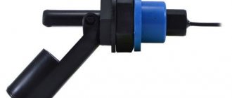
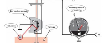
The float is at the top - the contacts are open.
The float is in line with the sensor axis - the contacts are closed.
Wire length 0.38m.
It is advisable to use float sensors to control the level of non-conductive liquids: distilled water, oil, gasoline. To turn on the pump to fill the tank, place the sensor with the float up (see photo). When the float rises, the pump turns off.
To pump out water, place the sensor with the float down. When the float rises, the pump turns on; when the float descends, the pump turns off.
Maximum switching power – 10W
Maximum constant voltage – 100V
Maximum alternating voltage – 220V
Maximum current – 0.5A
Resistance of closed contacts, no more than 0.1 Ohm
Temperature from -10 to +85 degrees C
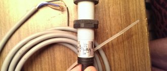
In some cases, high sensor reliability is required. Standard float sensors, due to their design features, may not have very high reliability when operating in a heterogeneous (dirty) liquid, with a large temperature difference, especially at subzero temperatures. The reliability of the actuator – the “reed switch” – is also not always sufficient.
In these cases, it is better to use a float with a mercury sensor:
I couldn’t find similar sensors for sale, so I made it myself.
Mercury sensor, parameters:
Current no more than 500mA, maximum voltage 100V, operating voltage 25V, temperature -20…+100 degrees C.
Silicone medical tube:
The temperature limits at which the tubes are not damaged are from -60° to +300°C. The silicone tube can withstand pressure up to 2 atmospheres. Used in peristaltic pumps, it has very high resistance to bending and tension-compression.
A mercury sensor is placed inside at the end of the silicone tube. At the location of the sensor, a plastic “cable gland” with a rubber seal is placed on the tube. The silicone tube with the mercury sensor is tightly compressed by the cable gland seal - firmly and hermetically. The ping pong ball is attached using heat shrink tubing. For strength and improved sealing, black heat shrink tubing is placed over the white heat shrink tubing. Another cable entry serves to seal and secure the float to the tank.
In the photo: disassembled cable gland, ping pong ball.
The length of the silicone tube is 30cm (10cm is enough for normal operation). Ball diameter 40mm. Wire length 50cm.
Triggers (contacts close) upon ascent, if the sensor position is 3-5 degrees above horizontal.
Float sensors can be connected to any of the level switches described above.
In some cases, it is impossible or extremely undesirable to connect level switches and actuators (pumps, water valves) to the network
220V. For example, in aquarium farming or small “indoor” greenhouses. The laying of wires with high (mains) voltage on the ground of the garden plot must be carried out in compliance with the rules and regulations of electrical safety.
In these cases, it is more convenient to power all this water supply from a 12V network. For example, from the appropriate power supply (adapter) or car battery. We change the relay power supplies (phone chargers) to the automotive version (12V):
The cheapest 12V pumps are car windshield washer pumps. You can connect such pumps to the level relay (options 1 and 2) through an automotive relay of the appropriate power, for example, this:
To keep your car battery always charged, it is not at all necessary to buy a powerful charger. In the vast majority of cases, an inexpensive recharge will do, for example, option 3.
The battery power option is especially convenient in rural areas where there are frequent power outages.
This relay option is for those who like to make their own. It is distinguished by high reliability, unpretentiousness in operation, versatility of use, and low price. There is no case.
Dimensions: 130 x 20 x 40 mm. There are 4 holes along the edges of the board for mounting with M3 screws.
The relay has fairly powerful contacts for a current of 10A:
This is enough to connect a pump with a power of no more than 500W. To connect a more powerful pump, we use an additional thyristor relay.
The high reliability of the “homemade” relay is due to the absence of a power supply. The current required to power the relay is limited by a 15 W incandescent light bulb (from the refrigerator). The light bulb burns at full intensity and does not burn out when the voltage in the network increases to 300 volts. The service life of the light bulb in this mode increases tens of times.
The light bulb can be replaced with a powerful resistor: resistor resistance 4-8 KOhm, power from 6 W.
The relay supply voltage is limited by zener diodes (fixed together with aluminum plates - heat sinks).
To improve noise immunity, there is a delay for turning on/off the relay of 0.5-1 seconds.
The efficiency of these relays is somewhat worse than that of electronic relays with a power supply. Let's compare: a homemade relay consumes no more than 9 W, electronic relays consume no more than 5 W.
We insert the wires into the terminal block, tighten the screws:
Refrigerator light bulb 15 W:
If you do not find a suitable light bulb from the refrigerator, you can use an energy-saving light bulb with a power of 13-18 W. It will also burn at full intensity. But the reliability of energy-saving light bulbs in this scheme is much lower than that of incandescent light bulbs.
The sensitivity of this relay is worse than that of electronic relays (see top of page). For this reason, the area of the sensor-electrode must be at least 15-20 cm^2 (the size of a matchbox).
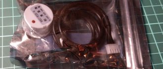
For example, a sensor for an artesian well pump:
A plastic tube of suitable diameter is fixed (at the required height) on a wire and cable to the pump. The electrode is a piece of tin from a tin can, glued to the outside of the tube. The photo shows a piece of a tube from a halahup.
Electrode in water - pump on. The water level is below the electrode - the pump is turned off.
According to electrical safety requirements, the pump mounting cable must be grounded. The cable is a common wire for sensor electrodes, similar to electrode No. 1 in electronic relay circuits (see above).
The electronic relays described above have a useful hysteresis function: on at one level, off at another. Moreover, these levels can be adjusted by moving the sensors (tin plates) in height. Hysteresis is easy to add to this relay design. We install 2 sensors and connect them through a resistor.
Resistor resistance 1 KOhm, power not less than 0.1 W.
The photo shows a 0.25 W resistor (included in the relay kit).
The “homemade” relay is similar in its capabilities to electronic relays options 1,2 and T1, T2.
It is advisable to place it inside a suitable plastic box, which usually houses starters, circuit breakers and other electrical equipment (sold in electrical goods stores and construction markets). A constantly burning light helps reduce humidity inside the box. When connecting an inductive load (pump), to increase the service life of the relay contacts, it is advisable to add an arc-extinguishing (interference-suppressing) RC circuit in parallel to the contacts (+20 rubles):
Simple and reliable water level sensor
made from a tin lid for home canning
and a piece of thick wire complete with cable gland:
The wire is securely soldered into the hole in the cover
The wire thickness of 4.6 mm was chosen for reasons of strength and reliability (core cross-section 4 mm^2).
We connect any thin wire to the outer end of such a wire, stretch it, and connect it to the water level switch.
The diameter of the tin lid is approximately 90 mm. Cut with scissors to the required size.
The cable gland can be plastic or metal
If it is difficult for you to make such a sensor, you can buy it from me.
Cost of one sensor: 100 rub. (cover, soldering, plastic cable gland) + 40 rub. for each meter of thick (as in the photo) wire.
Replace the plastic cable gland with a metal one +50 RUR.
Example: to connect a level relay, 3 sensors are required. The length of the wire of the upper level sensor is 1, the length of the wires of the lower level sensor and the common wire (terminal No. 1) is 2 m each. 1+2+2=5m
100 x 3 + 5 x 40 = 300 + 200 = 500 rub.
You can try soldering a 5 ruble coin.
The big advantage of mounting a cable gland sensor on the tank lid is that there is no salt deposits on the top of the sensor wire. Please note: the tank cover or other location where the wire (cable entry) is attached should not be wetted with water other than splashes, isolated drops or vapors.
Salt deposits (scale formation) impair the accuracy and reliability of the relay. Adjusting the sensitivity of the relay is not a panacea and is therefore absent from the water level relays described above.
Salts (scale) are a conductor, they close the contacts of the sensors in the absence of water, and can lead to false operation of the relay. For this reason, at least a small section of sensor wire or tank lid or cable glands are required without scale.
Do-it-yourself water level controller in the tank
ORDER ON THE OFFICIAL WEBSITE STORE