Where you should definitely start connecting the engine: 2 important time-tested points
Before turning on any electric motor for the first time, it is necessary to clarify its structure: the design of the stator and rotor, the condition of the bearings.
From my own and other people’s experience, I can assure you that it is easier to loosen a few nuts, inspect the internal structure, identify defects at the initial stage and eliminate them, than to deal with complex repairs that could have been prevented after starting a short operation.
Important Warning
Novice electricians quite often create engine malfunctions themselves, violating the technology for disassembling it, working with an ordinary hammer: they break the edges of the shaft.
To preserve the structure of parts without damaging them, it is necessary to use a special electric motor bearing puller.
In the most extreme case, when it is not available, blows with a hammer are applied through thick plates of soft metal (copper, aluminum) or dense dry wood (apple tree, pear tree, oak).
How bearing condition affects engine performance
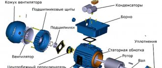
Any asynchronous electric motor (IM) has a rotor with squirrel-cage windings. A current is induced in them, creating a magnetic flux that interacts with the rotating magnetic field of the stator, which is its source of movement.
The rotor inside the housing is mounted on bearings. Their condition greatly affects the quality of rotation. They are designed to ensure easy sliding of the shaft without backlash or runout. Any violations are unacceptable.
The fact is that the stator winding can be considered as an ordinary electromagnet. If the rotor's bearings are broken, then under the influence of the magnetic field it will begin to be attracted, approaching the stator winding.
The gap between the rotating and stationary parts is very small. Therefore, touching or beating the rotor can touch, scratch, or deform the stator windings, irreversibly damaging them. The repair will require a complete rewinding of the stator, and this is a very difficult job.
Be sure to disassemble the electric motor before connecting it, and carefully inspect its entire internal structure.
Pay special attention to the condition of the bearings, compliance with tolerances and fits, and quality of lubrication. Dry and old lubricant must be replaced with fresh one.
What should be taken into account in the design of stator windings and how to prepare them
The home mechanic most often comes across electric motors that have already been used somewhere, and, perhaps, have undergone reconstruction or rewinding. Nobody usually declares this, the information on nameplates and tags is not changed, it is left the same. Therefore, I recommend visually inspecting their insides.
Stator coils for asynchronous motors for power supply from single-phase and three-phase networks differ in the number of windings and design.
A three-phase electric motor has three absolutely identical windings, spaced apart in the direction of rotation of the rotor by 120 angular degrees. They are made of one wire with the same number of turns.
They all have equal active and inductive resistance and occupy the same number of slots inside the stator.
This allows you to initially assess their condition with a conventional digital multimeter in ohmmeter mode with the voltage turned off.
A single-phase induction motor has two different windings on the stator, separated by 90 angular degrees. One of them is designed for long-term passage of current in the nominal operating mode and is therefore called the main, main or working.
To reduce heating, it is made with a thicker wire that has lower electrical resistance.
A second winding of greater resistance and smaller diameter is mounted perpendicular to it, which makes it possible to distinguish it visually. It is designed for short-term flow of starting currents and turns off immediately when the rotor reaches the rated speed.
The starting or auxiliary winding occupies approximately 1/3 of the stator slots, and the rest is allocated to the working turns.
However, this rule has exceptions: in practice, there are single-phase electric motors with two identical windings.
To connect the stator to the power supply, the ends of the windings are brought out with wires. Taking into account the fact that one winding has two ends, a three-phase electric motor can, as a rule, have six terminals, and a single-phase motor can have four.
But there are exceptions to this simple rule related to internal switching of pins to simplify installation on special equipment:
- for three-phase motors, the following can be removed from the stator: three wires when internally assembling a delta circuit;
- or four - for a star;
- three outputs with internal combination of one end of the starting and working windings;
- or six ends for a design with a starting winding and a built-in contact for disconnecting it from the centrifugal regulator.
As you can see, it is possible to judge the design of an asynchronous motor by the number of wires connected to the terminal block from the stator windings, but the probability of error is quite high. A more thorough analysis of its structure is needed.
Technical condition of winding insulation
Where and under what conditions the stator was stored is not always known. If it was unprotected from precipitation or inside wet rooms, then its insulation requires drying.
At home, the disassembled stator can be placed in a dry room to dry. It is possible to speed up the process by blowing a fan or heating with conventional incandescent lamps.
Make sure that the heated glass of the lamp does not touch the winding wire; ensure an air gap. The end of the drying process is associated with the restoration of the insulation properties. This process must be controlled by measurements with a megohmmeter.
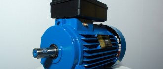
Design features and diagram of a single-phase 220V electric motor.
The main elements of a single-phase motor are the rotor and stator. The first component is mobile during operation, the second is at rest. The stator is equipped with two types of winding: main and auxiliary. Otherwise they are called working and starting. Both types are located at an angle of 90 degrees in the core and are securely fixed in the grooves.
The main winding makes up the majority, and the auxiliary winding is allocated only 30–35%. As for the rotor design, it consists of rods made of non-ferrous metals. At the ends, the elements are closed with special rings. The free space between the rods is filled with aluminum alloy. Because of its hollow appearance, experts and designers called the rotor of a 1-phase motor a “squirrel cage”.
Connection diagram for an asynchronous motor with a starting winding: assembly sequence
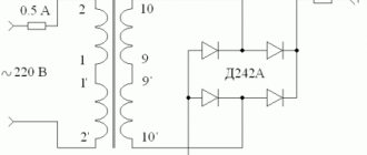
For example, we have determined that there are four or three wires coming out of the stator. We call up the active resistance between them with an ohmmeter and determine the starting and operating windings.
Let’s assume that four wires have two pairs with resistances of 6 and 12 ohms connected to each other. Let's randomly twist one wire from each winding, designate this place as a “common wire” and get a measurement of 6, 12, 18 Ohms between the three terminals.
I marked the beginnings of the windings with dots on this diagram. For now, ignore this question. But, you will need to return to it further when the need arises to reverse.
The chain between the common terminal and the lower resistance 6Ω will be the main one, and the larger 12Ω will be the auxiliary, starting winding. Connecting them in series will show a total result of 18 ohms.
We mark these 3 ends with markings that are already clear to us:
- O - general;
- P - starting;
- R - worker.
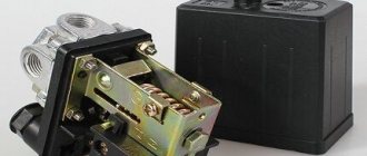
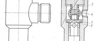
Next we need a PNVS button, specially designed for starting single-phase asynchronous motors. Its electrical circuit is represented by three closing contacts.
But, it has an important difference from the start button of three-phase NVD electric motors: its middle contact is made with self-return, and not fixed when pressed.
This means that when the button is pressed, all three contacts are closed and held in that position. But, when you release your hand, the two outer contacts remain closed, and the middle one returns under the action of the spring to the open state.
We connect this button and the terminals for the output of the stator windings from the electric motor with a three-core cable so that the starting winding contact goes to the middle contact of the PNVS. We connect pins P and P to its outermost contacts and mark them.
On the back side of the button, between the contacts of the starting and working windings, we rigidly mount a jumper. We connect a 220 volt household power cable with a plug for installation in a socket to it and the second outer contact.
When this button is turned on, all three contacts will close, and the working and starting windings will begin to work. In just a couple of seconds the engine will finish accelerating and return to nominal mode.
Then the start button is released:
- the starting winding is switched off by self-return of the middle contact;
- the main winding of the motor continues to spin the rotor from a 220 V network.
This is the most affordable connection diagram for an asynchronous motor with a starting winding for the home craftsman. However, it requires the presence of a ventilator button.
If it is not there, and the electric motor urgently needs to be started, then it can be replaced with a combination of a two-pole circuit breaker and a conventional electric button of the appropriate power with self-reset.
You will have to turn them on at the same time, and release the button after spinning up the electric motor.
Always perform all starts of electric motors and any electrical equipment with the protection of these circuits by circuit breakers. They will prevent the development of emergency situations when any random errors occur.
In order to consolidate the material on this topic, I recommend watching the video of the owner Oleg pl. It just shows the design of a built-in centrifugal regulator designed to automatically turn off the auxiliary winding.
Design features and diagram of a single-phase 220V electric motor
The main elements of a single-phase motor are the rotor and stator. The first component is mobile during operation, the second is at rest. The stator is equipped with two types of winding: main and auxiliary. Otherwise they are called working and starting. Both types are located at an angle of 90 degrees in the core and are securely fixed in the grooves.
The main winding makes up the majority, and the auxiliary winding is allocated only 30–35%. As for the rotor design, it consists of rods made of non-ferrous metals. At the ends, the elements are closed with special rings. The free space between the rods is filled with aluminum alloy. Because of its hollow appearance, experts and designers called the rotor of a 1-phase motor a “squirrel cage”.
Wiring diagram for an asynchronous motor with capacitor start: 3 technologies
The stator with windings for starting from capacitors has approximately the same design as discussed above. It is difficult to distinguish it by appearance and simple measurements with a multimeter, although the windings may have equal resistance.
Refer to the nameplate and table from Aliyev’s book. You can try to connect such an electric motor using a circuit with a PNVS button, but it will not spin up.
It will not have enough starting torque from the auxiliary winding. It will hum and twitch, but will not reach the rotation mode. Here you need to assemble a different capacitor starting circuit.
The 2 ends of different windings are connected to a common terminal O. A household voltage of 220 volts is supplied to it and the second end of the working winding through an AB switching device.
The capacitor is connected to the terminals of the starting and operating windings.
As a switching device, you can use a double circuit breaker, a switch, NVD or NVDS type buttons.
Here it turns out that:
- the main winding operates directly from 220 V;
- auxiliary - only through the capacitor.
This circuit is used for easy starting of capacitor electric motors that are put into operation without heavy load on the drive, for example, fans, sanders.
If, at the moment of starting, it is necessary to simultaneously spin the belt drive, gear mechanism of the gearbox or other heavy drive, then a starting capacitor is added to the circuit, which increases the starting torque.
It is convenient to describe the operating principle of such a scheme using the same PVS button.
Its self-resetting contact is connected to the auxiliary winding through an additional starting capacitor Sp. The second end of its plate is connected to terminal P and working capacity Cp.
An additional capacitor at the moment of starting an electric motor with a heavy drive helps it quickly reach its rated rotation speed, and then simply turns off so as not to create overheating of the stator.
This circuit is fraught with one danger associated with long-term storage of a capacitive charge by the starting capacitor after removing power 220 when the electric motor is turned off.
If the worker is not careful or careless, the discharge current can pass through the human body. Therefore, the charged capacity must be discharged.
In the scheme under consideration, after removing the voltage and pulling out the plug and power cord from the socket, this can be done by briefly turning on the PVS button. Then the capacitance Sp will begin to discharge through the starting winding of the motor.
However, not all people do this for various reasons. Therefore, it is recommended to install two additional resistors in the starting circuit.
Resistance Rр is selected with a nominal value of about 300÷500 Ohms of several watts. Its task is to discharge the auxiliary capacitance Sp after removing the supply voltage.
The Ro resistor is low-resistance and powerful and acts as a current-limiting resistance.
Adding resistors to the electric motor starting circuit increases the safety of its operation and automatically limits the flow of capacitive discharge current of a charged capacitor through the human body.
Where can I get the values of the main and auxiliary capacitors?
The fact is that the factory determines the value of the starting and operating capacitance for capacitor starting of a single-phase IM individually for each model and indicates this value in the passport.
There are simply no separate formulas for calculating how it is done for capacitor starting of a three-phase motor in a single-phase network using star or delta circuits.
You will need to look for factory recommendations or experiment during the setup process with different containers, choosing the most optimal option.
The owner of the video “IV I'm Interested” shows how to optimally configure the parameters of a capacitor motor starting circuit.
How to distinguish on a single-phase motor
Single-phase motors are equipped with two types of winding so that their rotor can rotate, since only one is not enough for this. Therefore, before connecting the motor, you need to figure out which skein is the main one and which is the auxiliary one. There are several ways to do this.
By color coding
What type a particular skein is can be determined by color markings during a visual inspection of the engine. As a rule, red wires are of the working type, but blue wires are of the auxiliary type.
But all rules have their exceptions, so you should always pay attention to the electric motor tag, on which a decoding of all markings is applied
However, if the engine has already been repaired or there is no tag on it, this method of checking is not effective. In the first case, during repair work, the internal contents of the motor could completely change, and in the second, there is no way to accurately decipher the color symbols. In addition, sometimes there may be no markings at all. Therefore, in such situations, it is better to resort to another, more reliable method.
By wire thickness
The thickness of the wires that come out of a low-power electric machine will help distinguish the starting coil from the working one. Since the auxiliary one works for a short time and does not experience serious load, the wires related to it will be thinner.
But even if it catches your eye, you shouldn’t rely on that alone. Therefore, many always measure the resistance of wires.
Using a multimeter
A multimeter is a special device that allows you to measure the resistance of wires, as well as their integrity. To do this, you must follow the following algorithm:
- Take a multimeter and select the desired function.
- Remove the insulation from the motor wires and connect any two of them to the probes of the device. This is how the resistance force between the two motor wires is measured.
- If no numerical values appear on the device screen, then you need to replace one of the wires and then repeat the procedure. The readings obtained will refer to the terminals of one skein.
- Connect the probes of the measuring device to the remaining wires and record the readings.
- Compare your results. Electrical wires with a stronger resistance will belong to the starting coil, and those with a weaker resistance will belong to the working coil.
Once the measurements have been determined and it becomes clear which electrical wires belong to which coil, it is recommended to mark them in any convenient way. This will allow you to skip the resistance measurement procedure when connecting the motor in the future.
There are several ways to distinguish where the starting winding is and where the working winding is of a single-phase motor. However, the most effective of them is to measure the resistance of the electrical wires coming from a low-power electric motor using a multimeter.
Installation and selection of components
Capacitors have considerable dimensions, so they do not always fit into the inside of the boron (distribution box on the electric motor housing).
Depending on the installation location and other operating conditions, the capacitors may be located on the outside of the motor near the junction box. In some cases, the capacitors are placed in a separate housing located near the electric motor.
The capacitance value of capacitors in the ideal case with a constant current load can be calculated, but in most cases the load is unstable, and the calculation method is complex. Therefore, experienced electricians are guided by statistics and practical experience:
- for the capacitors of the operating circuit, the capacitance is selected as 0.75 μF per 1 kW of power;
- for starting capacitors 1.8–2 μF per kW of power, while voltage surges during the start and stop period must be taken into account - they range from 300–600 V. Therefore, the voltage of the capacitor must be at least 400 V.
In general, when choosing a circuit and capacitors for a single-phase motor, one must be guided by the purpose of the motor and operating conditions. When you need to quickly spin up the engine, a circuit with a starting capacitor is used. If it is necessary to have greater power and efficiency during operation, a circuit with a working capacitor is used - usually in a single-phase capacitor motor for domestic needs of low power, within 1 kW.
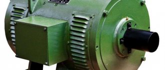
Model overview
One of the most popular are electric motors of the AIR series. There are models made on feet 1081, and models of combined design - feet + flange 2081.
Electric motors in the foot + flange design will cost about 5% more than similar ones with feet.
As a rule, manufacturers provide a warranty of 12 months.
For electric motors with a rotation height of 56-80 mm, the frame is made of aluminum. Motors with a rotation height of more than 90 mm are available in cast iron.
Models differ in power, rotation speed, height of the rotation axis, and efficiency.
The more powerful the engine, the higher its cost:
- An engine with a power of 0.18 kW can be purchased for 3 thousand rubles (electric motor AIRE 56 B2).
- A model with a power of 3 kW will cost about 10 thousand rubles (AIRE 90 LB2).
The height of the rotation axis for motors with 1 phase varies from 56 mm to 90 mm and directly depends on the power: the more powerful the engine, the greater the height of the rotation axis, and therefore the price.
Different models have different efficiencies, typically ranging from 67% to 75%. Greater efficiency corresponds to a higher cost of the model.
You should also pay attention to engines produced by the Italian company AACO, founded in 1982:
- Thus, the AACO series 53 electric motor is designed specifically for use in gas burners. These motors can also be used in washing installations, warm air generators, and central heating systems.
- Electric motors of the 60, 63, 71 series are designed for use in water supply installations. Also, the company offers universal motors of the 110 and 110 compact series, which are distinguished by a diverse range of applications: burners, fans, pumps, lifting devices and other equipment.
You can buy motors produced by AACO for a price starting from 4,600 rubles.
First, let's find out the type of engine. We will not always resolve the issue unambiguously. Appearance says little; the nameplate of an old engine may not correspond to the actual contents of the unit. We propose to briefly consider what asynchronous and commutator motors the industry produces. We will tell you the differences in operation, key properties, external and internal. Let's discuss connecting a single-phase motor to an AC mains.