General view of the screwdriver
Screwdrivers can be corded or corded. The difference between them is the power source. The shape of the tool is similar to a pistol. The screwdriver design and general view are shown in the photo.
A screwdriver is structurally similar to an electric drill and consists of the following components:
- a body that smoothly turns into a handle and a support leg to which the battery is attached and there is a cavity - a block for storing bits.
- Control buttons;
- Battery or power cord.
Electronic screwdriver speed control
The rotation speed of the screwdriver attachment can be adjusted mechanically or automatically. Automatic speed control occurs using a processor. You can set the desired operating parameters using the speed selection toggle switch. It is located on top of the body. In many models, speed control is realized through the start button. The stronger the finger pressure on it, the higher the speed will be.
After reading this article, you received information on how to assemble a screwdriver speed controller with your own hands, became familiar with the design of the force regulator, and understood the function of electronic adjustment of the tool. We hope you found the article useful.
Screwdriver body
The power tool is “packaged” in a plastic case, a material with the following advantages:
- Plastic serves as a natural insulator from electricity; it does not conduct electricity. Therefore, it is safe.
- It is lighter than metal, and thus reduces the weight of the tool.
- And finally, in production, plastic is easier to shape into the desired shape than metal.
The body is conventionally divided into three parts. All rotating mechanisms are located in the upper part. The handle is equipped with soft pads. The master holds the tool with it while working. The pads reduce shock absorption, making work more comfortable and easier. The lower part, the support, inside of which there is a compartment for storing bits.
History of the device
A screwdriver is a power tool.
Its main purpose, as the name suggests, is to tighten or unscrew a fastener. After the electric drill was invented in 1868, the development of power tools became widespread. Founding companies DeWalt, Bosch, Black & Decker, Makita and Hitachi developed the industry by creating new devices. The introduction of the Phillips head screw in 1934 created a demand for electric tools to tighten them. It was especially in demand in mechanical engineering. The first device of this kind was called a wrench. With the advent of batteries, the device gained mobility, and the name screwdriver came into use. Its mass production began in the early 80s .
Modern devices are constantly improving, but to a greater extent this relates to the method of autonomy and control. The design of the device remains unchanged.
This is interesting: Concrete drill bits for drills: types and models
Trigger switch and LED lighting
The trigger switch is located between the top of the housing and the handle. It is located under the master’s index finger, and it is convenient to use it to put the tool into operation. The trigger button closes the electrical network of the screwdriver and starts the electrical mechanisms.
The photo shows the device of the trigger button.
Some models of screwdrivers have built-in LED lighting that illuminates the work area. This is prudent and convenient, since in dimly lit areas it can be difficult to see the screw slot. In the model shown in the picture, the backlight is located in the lower part of the body above the trigger; in some Western European models it is located on the leg above the battery.
Instrument power supply
The supply of DC power to the electric motor of the screwdriver is carried out from a 220 volt network or using a battery. It is produced in a small-sized and compact design. This is necessary to reduce the weight of hand tools and ensure ease of work. The power supply device consists of several galvanic elements.
The batteries are combined into one housing and form a single unit. The supply voltage, depending on the scope of application of the screwdriver, may be different. For household equipment it is 9 volts, and for professional models it can reach 18 volts. The power of a power tool is directly proportional to the amount of voltage supplied.
Using information about the structure of the tool’s mechanisms, a person will be able to repair the screwdriver himself, saving time and money.
Speed control unit and speed switch
The rotation speed and reverse (rotation direction) control unit is connected to a PWM controller, a multi-channel single-pole transistor and a variable resistor, which are hidden in the switch block.
To change the direction of rotation, a changeover contact is used, to which a reverse switch is connected, located above the trigger at the bottom of the screwdriver. It is connected to a changeover contact, which changes the polarity of the voltage supplied to the electric motor. Thanks to this, the direction of rotation changes, which allows screws, self-tapping screws, and screws to be screwed in and out.
Another button is a gearbox speed switch which changes the rotation speed of the chuck. This occurs due to the fact that when the speed button is turned from one mode to another, the bracket (rocker arm) comes into motion, moving the gearbox gear from one level to another.
Transistors STP60NF06. Screwdriver repair
At some point, during a cold start (after storage), the screwdriver began to ignore the force of pressing the button, immediately turning on the maximum speed.
After rummaging around on the net, I decided to first clean the insides of the button, since there was a possibility that the problem was the accumulated metal filings on the sliding contacts. I still don’t understand whether this is true, because during the assembly process I mixed up the polarity of the insert diode, which led to the transistor burning out. So I had to order a new one. To understand what I did wrong, I found a diagram of a button on the same chip as mine (GS069). It is slightly different; instead of a resistive track (potentiometer), I have tracks for resistive dividers on the board, but otherwise the circuit is the same. I noticed in time that both diodes in the diagram are shown with reversed polarity, otherwise it would have burned out another transistor. The mentioned insert diode does not have any markings and looks like a small iron washer with insulation around the perimeter; next time I disassemble the button, I will take a photo and show it here. Polarity is determined by a multimeter in dial mode.
I saw ready-made assemblies with a transistor and a button in a local store, they cost from 400 rubles. Perhaps the entire assembly should have been replaced at once, given the noticeable wear of the contacts, but I decided to save money; it was better to buy a normal tool for the money. Or, for a thousand and a half, you can rent just another Chinese screwdriver for the season with new gears, a motor, and a button. Replace it with a good battery and continue buzzing quietly.
At the time of delivery of the new transistor, I installed the less powerful IRFZ24N (17 A versus 60 A and 55 W versus the old 110 W); I couldn’t find anything else. The transistor is the same type, I was not afraid of compatibility. In all modes with the limit clutch turned on, the screwdriver does not develop enough power so that even such a relatively weak transistor is not enough. The mosfets parallel well; for reliability, you could assemble a sandwich from a couple of IRFZ24Ns.
I temporarily decided not to use the tool in difficult situations when it was necessary to remove restrictions, but my plans were disrupted when I urgently had to unscrew a hefty screw. At the maximum limit, the protection (ratchet) was constantly activated, the screw did not budge. I took a risk by setting the drill mode (without restrictions), and calmly did the job. But now the button again stopped responding to gradual pressure, immediately turning on the engine to maximum.
Having disassembled the screwdriver, I discovered that the replacement transistor had burned out and all its leads were short-circuited. I don’t know whether such transistors can burn out gradually. If so, then it is likely that the previous soft start problem could have been caused by the transistor. Perhaps installing a more powerful battery somehow affected the life of the transistor. New transistors were still on the way, so I inserted a second spare IRFZ24N for now. It was necessary to immediately put the pair in parallel, perhaps they would have pulled out a larger load, but it was not clear how to install both of them on a standard radiator. In general, I was lazy and paid the price.
Let's return to the order. I am 100% sure that the transistors ordered are not originals, because this is AliExpress, and there they only look for originals... but no one looks for them, everything is so obvious. On the other hand, I'm almost sure that the old transistor was fake too. The tool is Chinese, the likelihood of imported parts getting into it if there are cheap ones of our own is very unlikely.
There are no difficulties with installation. It makes sense to shorten the legs so they don't get in the way. The wires are soldered to the legs of the transistor with minimal overlap, so that later the soldering area can be covered with a plastic insulator. You can put thermal paste under the transistor. Initially it was not there, the surface under the transistor is uneven, but the transistor almost does not heat up during operation. The legs are tinned well, there were no problems with soldering, except that the legs are a bit soft and you need to handle them carefully; the legs of the old transistor are also soft.
I didn’t bother assembling a test bench or measuring the characteristics of the transistors, and I simply had nothing to drive them to the maximum parameters, except perhaps with a screwdriver itself, which is what I did. From past experience, I already knew that I still had to try harder to load the tool, so I immediately took a 6-mm screw under the PZ3 head and tried to screw it into a wooden block. The first 5 cm passed on the last tick of the fuse, after which the ratchet engaged. I set it to “drill” (unlimited mode) and drove the screw all the way.
And this is where things started to get interesting. White smoke with a noticeable odor began to emerge from under the ventilation grille. Burnt transistors smell different, most likely the motor windings are stinking. I quickly took the screwdriver apart and rummaged around everything inside. The button and the motor are the hottest, but the transistor is a little warm and intact. The smell is from the engine. This is not the first time that smoke has come out of this screwdriver; it also happened on the old battery, while it was fresh, under a heavy and long load, that is, this behavior of the tool seems to be normal :-), and the new transistor is not to blame.
The transistor has clearly coped with the maximum developed power of the instrument, and so far there are no complaints about it. I’ll add to this post later, the summer season is ahead, there will be something to check.
In stores you can find it under the line “stp60nf06”. You can also look for more powerful transistors, supply and demand may work in their favor. Lots less than 5 pieces seemed to me unnecessarily expensive (per piece), five pieces cost 130 rubles (26 rubles/piece). In the nearest local radio parts store I could buy them individually for 30-35 rubles per piece, but with transport or delivery it would be another +300 rubles, at a minimum. It is very likely that they are even original, but in practice it turned out that imitation is enough.
Update dated May 19, 2016
Coincidentally, during the first real use of the screwdriver after replacing the transistor, it suddenly rattled loudly and stopped turning the chuck. It turned out that the engine had unscrewed from the gearbox unit. If your screwdriver starts making rattling sounds, you may have the same problem - loosening of the mounting screws, which will eventually lead to their complete unscrewing. It’s easy to check - the engine and gearbox unit must be firmly connected, without play.
There is nothing to do with replacing the transistor, other than a coincidence in time
Chuck with locking mechanism
A planetary gearbox transmits torque to a shaft onto which a self-centering chuck with attachments or bits inserted into it is screwed. The quick-release chuck ensures the fixation of screwdriver and drill bits; it consists of a holder, inside of which there is a clamping sleeve with movable jaws.
The shaft to which the chuck is screwed is equipped with a locking mechanism, which consists of an outer and inner housing and rollers installed between the housings and preventing rotation.
Speed controller: nuances
Capabilities of household screwdrivers.
The speed regulator is also made according to a very simple scheme. This involves a pulse-width controller and a switch, which is based on a field-effect transistor. As for control, a variable resistor is used here. Its resistance, and therefore the speed of rotation, directly depends on the force of pressing the power button. It is also sometimes called the trigger. Reversing only affects the direction of the voltage applied to the motor. Here, special changeover contacts are used for these purposes. The entire process is automated, so a person does not have to do anything manually.
This is interesting: How to check a screwdriver battery with a multimeter and tester
Rechargeable battery with locking button
Since the screwdriver can be cordless and wired, the power supply system in them is different. The cordless screwdriver has a built-in rechargeable battery, which is a device with built-in external contacts for transmitting electricity. The main element of the battery is its power supplies connected in series. Otherwise they are called banks, sample in the photo.
It also has a thermostat that protects the battery from overheating when charging. The rechargeable battery is a removable device, since it must be replaced as the resource is exhausted. The battery is attached to the screwdriver with a locking button, which is located on the side in some models, and in the front in others. From the handle extend contact plates that connect to the battery and provide power.
Schematic Electrical Diagram of a Screwdriver
Now you have to use a soldering iron and unsolder the two elements from each other, as shown in the figure. Screwdriver design: 1 - speed controller with reverse, 2 - electric motor, 3 - gearbox.
Resistor Rx sets the highest current.
The graph shows how the temperature of the element temperature, the voltage at its terminals voltage and the relative pressure relative pressure change during charging. It can monitor battery parameters and, if necessary, reduce the current automatically. WE MAKE A SIMPLE BATTERY CHARGER with auto shutdown when fully charged
The electrical signal is supplied directly to the engine rotor through the commutator. Next, you need to carefully assemble the screwdriver button, install it in place and test it. When the breakdown occurred, I was on business in Orenburg and therefore contacted the service center for repairs there.
Replaceable battery.
The rather miniature size of this tool assembly is achieved using microfilm technology.
We visually inspect the condition of the button for dirt and damage. repairing a screwdriver, replacing the power button with your own hands
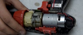
Engine
Now let's look inside the screwdriver body. The photo shows a cutaway screwdriver, or rather, with the cover removed.
A DC motor converts electrical current into mechanical energy, causing machinery to rotate. This is what the electric motor looks like in some power tools.
An electric motor consists of a stationary stator and a rotating rotor. The stator is a cylindrical metal casing with permanent magnets built around its walls.
Inside the housing there is a rotating rotor. It consists of a shaft on which a core is attached, which is a connection of plates made of high-tech steel, in the grooves of which winding turns of special copper wire are laid. When electrical energy is supplied, the rotor begins to rotate under the influence of these magnets and, through a gear pressed onto the shaft, transmits rotation to the planetary gearbox.
The circuit is connected to the motor through a brush mechanism consisting of two graphite brushes located opposite each other. During operation, the graphite brushes are gradually worn out, but pressure springs ensure their contact with the commutator.
Brushes are consumable parts and if the engine does not start, they are the first thing to check. The impeller serves to remove hot air and cool the engine. In the housing, opposite the impeller, there is a radiator grille.
Operating principle and main components
Before you start repairing a screwdriver with your own hands, you need to understand the principle of its operation and what parts it consists of. The main difference between a screwdriver and other power tools is the use of a mechanism that stops the rotation of the working part of the device. This happens when the maximum resistance configured for the instrument is reached. This value is not constant and can be adjusted. There are two types of device:
- operating from a 220 volt network;
- using a rechargeable battery.
Regardless of the type of device, their operating principle is the same and is based on the transmission of torque. It determines which fastening tool the screwdriver can tighten. To increase torque, devices use gearboxes with a large gear ratio, but the rotation speed is reduced. For screwdrivers operating on AC power, the torque value is related to the power consumption of the tool. The main parts underlying the device of a screwdriver, be it Makita, Hitachi or Bison, are as follows:
- electric motor;
- push button;
- speed controller with reverse;
- chuck;
- the electronic unit;
- gearbox
The electric motor rotates the spindle at a set speed using a planetary gearbox. The torque is controlled by a clutch, and a chuck or hex holder is placed on the spindle. A replaceable device called a “bit” is installed in this cartridge. The screwdriver is controlled by an electronic circuit and reverse switching .
Reverse occurs by changing the polarity of the power supply. The motor is a single-phase continuous current commutator motor. This motor is designed to be connected to an alternating current network. The field winding is connected in series with the armature winding and is divided into two parts. One turns on before the anchor, and the other after it.
The tool uses a planetary type gearbox. The gearbox includes sun and ring gears, satellites, and carrier. The electric motor shaft rotates the sun gear, which transmits torque to the satellites, and they directly affect the carrier.
The gearbox is available in one- and two-stage types. In the second case, a double carrier connected to the shaft is used. The design of two carriers and satellites is located in the middle of the ring gear. It is fixed through special grooves on the body. Along the entire perimeter, the lugs of the ring gear rest against spring-loaded balls through the ring. The load control mechanism acts on the ring through a controlled spring, the force of which is changed by moving the regulator.
Speed control is performed using a pulse circuit assembled on a pulse-width modulation (PWM) chip. The controller controls a field-effect transistor operating in switch mode. The pulse frequency is changed using a variable resistor. The resistance value of the resistor depends on the force applied to the button.
The screwdriver clutch is a ratchet. If the load on the cartridge exceeds the permissible value, the load regulator is activated. The spring force becomes insufficient to hold the ring gear, and it comes off the balls. The electric motor begins to rotate the gear idle. When switching to electric drill mode, this gear is turned off and does not participate in the work .
A rechargeable battery with a voltage of 12 V or 18 V is most often used as a power source. It characterizes the power of the device.
The battery consists of several elements installed in one housing and connected in series. The case has a special latch that allows you to quickly remove the battery.
Planetary reductor
The drive sun gear is also pressed onto the rotor shaft. A bracket in the form of a rocker arm is mounted on the engine body, with the help of which the gear stages are switched.
Screwdriver gearbox
The differential gearbox can be enclosed in a plastic housing. The arrangement of gears in a planetary gearbox depends on the number of switched speeds and may differ in different models. In a two-speed power tool, the gearbox has three stages. The first stage contains:
- sun gear;
- fixed ring gear;
- planet gears, small gears that rotate inside the ring gear.
- toothed drive.
The second stage serves to transition from the first stage to the third when changing gears. It consists of a planetary gear, which, with the help of a bracket, moves to the first and second rows of gears, due to which the rotation speed of the cartridge changes. It also has built-in satellites and carrier. The third stage is connected to a crown gear with protrusions at the end, 5 satellites, and a carrier with a cross-shaped grip.
The tightening torque clutch (the force applied by the screwdriver when performing work), also known as the torque regulator, consists of cylinders and balls, a housing, a washer, and a spring.
The clutch blocks the operation of the screwdriver if the load on the rotation mechanism increases, and thereby protects the screws on one side from failure, and the engine and planetary mechanism from unnecessary overloads and premature failure.
If you switch the screwdriver to drilling mode, the spring tightens and presses the washer as much as possible so that the third stage ring gear is blocked and its rotation is prevented. Thanks to this, the operation of the cartridge is not blocked. This video shows how a screwdriver works.
Cartridge
When using the tool, various attachments for screws and drills are used. Their tip in the standard version is made in the form of a hexagon. To secure such attachments and to transmit rotation to them, there is a cartridge. This element is installed on the spindle. The chuck is secured with a special screw, which prevents it from loosening during rotation.
Screwdriver chuck diagram
The most common version of this unit is called three-jaw, self-centering and self-clamping. Inside the cartridge there is a recess with a hexagonal profile. The attachments are fastened by rotating the coupling, which allows them to be fixed between the cams. The coupling also contains a retainer. It can be used to clamp attachments, which prevents spindle rotation.
Related video: Screwdriver - a look from the inside
Publications on the topic
Self-conversion of a cordless screwdriver into a corded one
Screwdriver battery recovery algorithm
Principles of installation and arrangement of a valley roof
Features of corded and cordless screwdrivers
In corded screwdrivers, the power source is a 220V electrical network and a power cord is built into the handle of the power tool. To work with corded power tools, an electrical outlet is required; this is a disadvantage of such tools. However, a constant power source and voltage of 220 V do not limit the power of such power tools. It's no secret that batteries are limited in this regard. They are also limited by operating time, after which the battery must be charged.
A cordless screwdriver with a rechargeable battery is appreciated by motorists who have to carry out repairs in the absence of a constant power supply, somewhere on the highway, and by builders, since remote construction sites are not always provided with electricity in a timely and stable manner.
Power supply and its characteristics
The screwdriver motor can be powered by mains or battery power. Models equipped with a wire for connecting to an alternating current network have limitations in operation and are less compact. However, they have increased power and operational reliability.
Screwdrivers with a constant current source are equipped with 1 or more batteries. Its power can vary from 9 to 36 watts. For solving household problems, the optimal power range is considered to be 12-15 W. The following types of batteries are used:
- lithium-ion (Li-Ion);
- nickel-cadmium (Ni-Cd);
- nickel metal hydride (Ni-MH).
They differ in voltage and service life. It is recommended to purchase screwdrivers with a 3.6 V Li-Ion battery. They are reliable and durable in operation. In addition, you should take into account the capacity of the power source, which directly affects the service life. It varies from 1.2 to 3.5 Ah.
Reference! It is advisable to purchase a model equipped with 2 or more batteries, which avoids interruption in operation. The technical documentation always indicates the charging duration; the shorter it is, the more convenient the tool.
When choosing a screwdriver, consider the purpose of the job. Professional tools are distinguished by increased engine power and 2-3 phases of gearbox operation. The case should be comfortable for the hand and comfortable for prolonged use. It is recommended that the spindle speed be adjusted, the minimum range is 0-1250 rpm. It is imperative to have a reliable and capacious power source; for convenience, it is advisable to purchase models with 2 or more lithium-ion batteries.
How does the ratchet mechanism work on a screwdriver?
In addition to the gear mechanism, the design of the tool also uses a device such as a torque regulator with a safety clutch. These two devices are related, but have a similar design. First, let's find out why we need a ratchet and a mechanism for adjusting the torque force, which is absent on drills and screwdrivers.
The screwdriver is designed to perform work on screwing screws and other fasteners. When screwing self-tapping screws into wood, different amounts of force are required, which depends on the length of the fastener, as well as the type of wood (hardness).
This requires varying degrees of force. The design has a mechanism called a ratchet. The operating principle of this mechanism is similar to a torque wrench. Once the appropriate force is achieved, which is set manually, the handle rotates relative to the key head. Let's look at what this mechanism is like on a screwdriver:
- One large spring or a set of springs, due to which the clamping force is adjusted
- Fittings or cams that serve to connect to the transmission mechanism. Balls from bearings are also used as fittings. In the example photo below, the protrusions are placed on the plate
- Grooves or grooves through which the fitting is connected to the spring acting on it
For ease of perception, on the outside of the device there are symbols in the form of numbers from 1 to 24 or more. The more numbers on the body of the force regulator, the higher the adjustment range. The stronger the springs act on the fittings, the greater the clamping force. Switching the regulator to a high value mode allows you to screw long screws into hard wood.
The clamping force regulator simultaneously performs a protective function, which eliminates the possibility of stator jamming. If the nozzle fixed in the tool chuck jams, then the fittings in the regulator slip along the grooves. The rotor overcomes the force, but does not jam. The absence of such a mechanism would lead to burnout of the rotor windings due to an increase in current.
In order to protect the tool engine from combustion, the design also uses a friction-type safety clutch. It is shown in the photo below, and is triggered when the nozzle jams. For example, the maximum force on the regulator is set, in this case, if the drill jams, then with a high degree of probability the device will be torn out of your hands. To prevent this from happening, a protective clutch is used, which prevents the tool from being pulled out of your hands and also prevents the winding on the rotor from burning out.
When the nozzle jams in the chuck, the engine rotor stops. To prevent such jamming, a safety clutch is used in the design. It works only in one mode, when the actuator rotates in the direction to the right. When the chuck rotates to the left, the clutch does not engage, as can be seen from the photo above. Typically, additional safety clutches are used on powerful screwdrivers from 14V. Below in the photo is a type of screwdriver clamping force regulator, the operating principle of which is similar to the description.
This is interesting!
Not all screwdrivers have safety clutches, as their role is played by force regulators.
How does a screwdriver or device design work?
The type of tool under consideration works on the principle of converting electrical energy into mechanical energy, thereby performing useful work. Based on this, screwdrivers are classified into corded and cordless. Rechargeable models are popular due to their portability, but networked ones also have the advantage of high power compared to rechargeable ones. Corded screwdrivers are also called drills, since they can not only screw fasteners, but also drill wood and metal.
This is interesting!
A close relative of cordless screwdrivers are impact wrenches, which not only have the same design, but also the same operating principle.
The external design of the network and battery models is almost identical, with the exception of minor differences. This difference lies in the presence of a battery on portable instruments, as well as the presence of a wire for connecting to an outlet on network-type devices. The internal structure has more differences, however, the operating principle of corded and cordless screwdrivers is the same. The main structural elements of the devices under consideration are:
- Impact-resistant plastic housing
- Chuck (usually quick-release type)
- A button, switch, or trigger for starting a tool
- Switch for direction of movement of the executive body - reverse
- Speed controller in the form of a switch
- Torque control - better known as a ratchet
To understand the device, below is a photo with a description of each element. The operation of the device is based on the following parts that are located inside the housing:
- Electric motor of commutator or brushless type
- Gear mechanism in the form of a planetary gearbox
- Safety clutch with force regulator - eliminates jamming and overheating of the motor, thereby preventing its failure
Depending on the model of the tool, they can also be additionally equipped with backlighting, battery charge indication or an LED display. The housing design may have grooves to accommodate replaceable bits, which makes operation of the device easier.
This is interesting!
Corded screwdrivers use 220V AC commutator motors, while cordless screwdrivers use both brushed and brushless DC motors. It should be noted right away that brushless models are less common, since their cost is 2 times higher than models with graphite or copper brushes.
Nickel – metal – hydride batteries
Nickel-metal hydride batteries are an attempt to get rid of the disadvantages of nickel-cadmium batteries:
- have less weight and smaller dimensions;
- low toxicity;
- low “memory effect”;
- good capacity indicators;
- resistant to mechanical damage;
- the number of charge-discharge cycles has been increased.
However
- they cannot be used at sub-zero temperatures;
- discharge quickly;
- service life is shorter than nickel-cadmium;
- high price;
- significant charging time;
- react negatively to deep discharge.
It should be admitted that the attempt to get rid of the shortcomings of nickel-cadmium batteries was not very successful.
Other Upgrade Methods
Radio amateurs offer many options for upgrading the instrument. Some of them are very simple and boil down to the use of ready-made power supplies, while others require knowledge in the field of electrical engineering and give the device versatility. Classification of methods:
- Power adapter for laptop.
- Connecting a computer switching power supply (power supply).
- Application: 12 V car battery.
- Assembling a homemade power supply.
Using a laptop charger is the best solution to the problem. In addition, you need to know the parameters of the screwdriver and charger (available for 12 V and 19 V), and also take into account the dimensions of the latter (for installation in the battery compartment). You need to solder the output of the laptop power adapter, to the terminals of which the battery is connected.
When using a switching power supply (power from 350 W and above) for a personal computer (AT form factor), you need to find a 12 V supply voltage on the connectors powering the hard drive or CD drive. Remove the wires, and carefully cut and insulate the rest. You can assemble a housing for the power supply, which will allow you to obtain a current of up to 16 A. In addition, you need to remove the start-up protection. To do this, you need to connect the green wire to the black wire from this connector. These two methods are very simple and do not require additional description.
A car battery is the optimal source of electrical energy. When upgrading the model, nothing changed except connecting a different battery. A significant drawback is its weight. In addition, you need to assemble a charger or purchase it at a specialized store.
Assembling your own power supply is the optimal solution for those who maintain quality. The previous options are good, but do not allow for flexibility of use. For example, they are only applicable for screwdrivers with a voltage of 12, and not 18 V. There are chargers designed for a voltage of 19 V. Obtaining 18 V is achieved by connecting batteries in series, for example, 12 and 6 V. Please note that according to the characteristics of the battery should differ only in terms of voltage. This is why it often becomes necessary to assemble a power source yourself.
Power supply options
You can use a standard charger for this purpose. Here's how to turn a cordless screwdriver into a corded one: you need to do the following:
- You need to remove the cover from the charger body.
- You need to make a hole in it for the connected two-core wire.
- On the board you can see the terminals to which the battery was previously connected for charging. You need to connect the cores of the prepared wire to them in order to remake the screwdriver for such work. In this case, you need to take into account the polarity of the terminals. To determine it, you need to look at the inscriptions on the board or on the device case.
- You need to open the screwdriver battery case and remove all the galvanic cells from it.
- Holes are made in it for the wire.
- The wires that were soldered to the terminals of the charger are connected, observing polarity, to the output contacts of the battery.
- Once the body is assembled, the tool can be used.
Although it is recommended to connect the power supply taking into account the polarity, however, if you connect the contacts in a different order, this will mean that the direction of rotation will change to the opposite. Most screwdrivers provide the ability to switch it, which makes it possible not to depend on polarity when switching.
Laboratory power supply
Using a laptop charger
The laptop charger can be replaced for this tool with only minor modifications. It receives AC voltage from a 220V network at the input, and produces 12V DC at the output.
However, it will still be necessary to modify the wires:
- The plug used for a laptop will not fit a screwdriver. Therefore, it will be necessary to cut the wire coming out of the charger and strip it.
- If necessary, you need to attach a cable of the required length to it.
- The tool body needs to be disassembled.
- The cable is connected to the terminals from which power is supplied to the screwdriver. You need to make a hole in the tool body for it.
- The tool, once assembled, will be ready for use.
Important. After the modification is completed, you will need to connect the power source to the network and make sure that the tool is in working condition.
Laptop charging power supply circuit
Computer power supply as a basis
You can power the instrument so that it uses the computer's power supply. Here's how else to make a power supply for a screwdriver: to remake this way, you need to do the following:
- You need to find or purchase a power supply with a power of at least 300 W.
- The screwdriver body needs to be disassembled and the location for connecting the wires to power the motor must be found. The cores of a pre-prepared wire are connected to them.
- A hole must be made in the housing for the wires to exit.
- To connect to the power supply, you will need special connectors. One of them is soldered to the wires coming from the screwdriver, the other is already installed on the wire that is connected to the computer power supply. This is necessary in order to power the screwdriver from the network
- Now we need to assemble the screwdriver body.
Now it remains to check how the tool works. To do this, you need to connect the power supply to a 220V outlet and plug in the screwdriver.
Power from car charger
You can convert this tool to be powered by a car battery. In this case, autonomy increases, since you can use the screwdriver in close proximity to the car.
In order to convert the voltage to 220 V you need:
- Disassemble the tool body. In this case, you can see the contacts to which power should be connected.
- It is necessary to prepare the wires that are used to charge car batteries. They have alligator clips. The other ends need to be carefully cleaned with a knife.
- Wires are attached to the contacts to power the screwdriver. They can be attached with zip ties or soldered. The last option will be more reliable.
- You need to make a hole in the tool body for the wires.
- Now the screwdriver body needs to be assembled.
To complete the work, you will need to connect the wires to the car battery using clamps.
Power from charger
Homemade power supply
Having made a power supply for a screwdriver with your own hands according to one of the diagrams, you need to insert the housing and connect it with wires to the motor of the tool.
Network block built into the battery
One of the options for converting a screwdriver into a network one is that the power supply, which converts 220V alternating current to 12V direct current, can be placed directly into the battery case. To do this you need to do the following:
- It is necessary to disassemble the battery housing.
- The contents are removed from it.
- You must first purchase a power supply that has the characteristics necessary for the screwdriver to operate.
- You need to remove the motherboard from the purchased device and install it in the case where the screwdriver battery was previously located.
- The output wires are connected to the battery contacts.
- For the input wires through which 220V voltage will be supplied, you need to make a hole in the housing.
- Now you need to assemble the screwdriver.
After the changes have been made, this tool can be used where electrical outlets are available.
Network block