Welding inverter is an established common name for welding machines that use an inverter converter as a current source. Such devices are used for various electric arc welding technologies: MMA (manual covered electrodes), TIG (argon arc) and MIG/MAG (in an inert or active gas atmosphere). Generally, all MIG/MAG and TIG welding inverters can also perform MMA welding. In addition, leading manufacturers produce combined units that combine all three types.
All these technologies have been developed for different types of welding and joining of various metals and their alloys. Before you start choosing a welding machine, you need to answer two questions: what types of welding are supposed to be performed and under what conditions it will work. Nowadays the market offers a huge number of models of both household and industrial welding equipment with the widest range of technical characteristics. It is very difficult to understand which one is better and which manufacturer to give preference to. The only way out in this situation is to independently understand the basics of welding technologies and the operating principles of modern equipment.
What is a welding converter?
Many beginners know only about inverter or semi-automatic welding equipment, unaware of the existence of other types of machines. But on the market you can still find a classic transformer, a rectifier, a welding generator and a welding unit. In addition to them, there is also a welding converter, which is not often used in modern welding. Nevertheless, it would not hurt to know about the existence of such equipment.
In this article we will describe in detail what a welding converter is, its purpose and design. We will also answer a frequently asked question: what is the difference between welding converters and units, also known as generators.
Main types of welding converters used in industry
Multi-station converters.
They are designed to simultaneously power several welding stations. In industry, multi-station converters PSM-1000, PSM-500 are used. The PSM-1000 converter has a single-case design of a stationary type and consists of a three-phase, asynchronous motor AB-91-4 with a squirrel-cage rotor and a six-pole generator SG-1000 with mixed excitation. In addition to the shunt winding. A series winding is placed on the main poles to maintain a constant voltage as the load increases. The generator has a rigid characteristic; the voltage is regulated by a rheostat connected to the parallel excitation winding circuit. The falling external characteristic required for manual arc welding is created independently at each welding station by a ballast rheostat of the RB type (this rheostat allows you to stepwise change the value of the welding current). The connection diagram for the PSM-1000 converter and ballast rheostats is shown in Fig. 105. The main disadvantage of multi-station converters is the low efficiency of welding stations. The advantages of multi-station converters include: ease of maintenance, low cost of equipment, small area for equipment placement and high reliability in operation. Converters for welding in shielding gases.
For automatic and mechanized welding in shielding gases, welding converters are required that provide rigid or increasing external characteristics. For this purpose, the industry produces converters PSG-350, PSG-500, as well as universal converters PSU-300 and PSU-500. Universal converters of the PSU type are designed for manual arc welding, surfacing and cutting of metals with direct current, since they provide steep external characteristics. In Fig. 106 shows the external characteristics of the PSU-300 converters.
The PSG-500 converter has a single-case design. The converter generator has two excitation windings at the main poles: one independent and the other serial, biasing. The electrical circuit of the PSG-500 converter is shown in Fig. 107. The independent excitation winding is powered from the alternating current network through a ferroresonant voltage stabilizer and a block of selenium rectifiers BC, which provide a constant, independent of fluctuations in the network voltage, the excitation voltage. The voltage at the generator terminals is smoothly regulated within 15-40 V by rheostat R, connected in series to the excitation winding circuit. The generator armature has low inductance, due to which, when the electrode is short-circuited with the workpiece, the welding current quickly increases; the current control limits are 60-500 A. The main technical data of PSG type converters are given in Table. 31.
Universal welding converters.
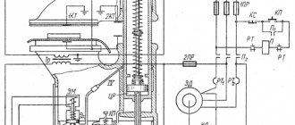
For manual arc welding and welding on automatic machines equipped with automatic voltage regulators that automatically affect the electrode wire feed speed, power sources with decreasing external characteristics are required. To power automatic and semi-automatic machines with a constant electrode wire feed speed, including for welding in carbon dioxide and SP-2 flux-cored wire, generators with strict external characteristics are required. As mechanized welding techniques are used in combination with manual arc welding in factories and installation sites, versatile sources are required that provide both slant and hard external characteristics. For this purpose, the design of the universal welding converter PSU-300 has been developed, the generator of which has one excitation winding. External characteristics in this generator are created using a DC triode connected to the excitation winding circuit of the OF, and feedback on the load current (Fig. 108). It is a four-pole DC generator of normal design, its OB excitation winding is located on the four main poles and is powered by a control device located on the converter housing.
The welding circuit and the excitation winding circuit are interconnected by a stabilizing transformer Tr, designed to ensure the dynamic properties of the generator. The amount of welding current is regulated by a rheostat - a DP regulator installed on the front control wall. As the welding current increases, the resistance of the triode increases, the excitation current decreases, and the emf of the generator also decreases, i.e., the characteristic turns out to be falling. When switching control circuits, the external characteristic becomes rigid. The main technical data of universal converters are given in table. 32.
general information
A welding inverter is a type of welding equipment that consists of two components: an electric motor and a welding generator. A typical representative is the PSO 500 welding converter.
The design of the welding converter is very simple. As we mentioned above, the main components are a generator and an electric motor. The electric motor runs on alternating current, and the generator runs on direct current. The operating principle is to convert alternating current from the engine into direct current by mechanically rotating the generator shaft. The shaft rotates manually, but thanks to the process of converting electrical energy.
Due to the need for mechanical rotation, such welding equipment is less reliable compared to rectifiers, for example. Also, compared to rectifiers, the efficiency is not so great. But the welding converter is practically insensitive to unstable voltage or to voltage drops. And in some conditions (for example, on a construction site) this is one of the most important factors when choosing welding equipment.
As with a transformer or rectifier, a welding converter does not have a separate, simple button or control to change the welding current. The current is regulated by a rheostat in an independent winding circuit.
Difference from welding unit/generator
Many welders confuse welding generators and converters. These types of welding equipment are very similar to each other; they have a similar structure and principle of operation. But there are still differences. Of these, the most important difference is the type of motor used to generate current.
For the converter, this is an electric motor; therefore, such an installation must be connected to an external source of electricity. And the generator has a fuel engine (gasoline or diesel), so such a device can be used for welding in field conditions where there is no electricity.
What is a converter?
A welding converter is a combination of several devices. It uses a combination of an AC electric motor and a special DC welding machine. The energy conversion process is as follows. The electrical energy supplied from the AC mains acts on the electric motor, causing the shaft to rotate, creating mechanical energy at the expense of electrical energy. This is the first part of the transformation. The second part of the operation of the welding converter is that during the rotation of the generator shaft, the generated mechanical energy will create a direct electric current.
However, it is immediately worth noting that the use of such devices is not very popular, since their efficiency is low. In addition, the engine has rotating parts, which makes it not very convenient to use.
Varieties
There are many types of welding transducers. We divided them into several groups.
Number of welding posts
The welding converter can be either single-station or multi-station. Single-station is designed to power only one welding arc. This means that only one welder can perform welding. Accordingly, from a multi-station installation, welding can be performed by several craftsmen at once, which is very convenient in production.
A multi-station converter has many advantages. You can connect several welding cables to it at once and weld with a large team, while avoiding high costs for repairs and maintenance, since there is only one installation. But the efficiency of a multi-point converter is significantly less than that of a single-point converter. So the choice of the number of posts depends on many factors.
Sometimes there is a situation when a single-station converter is the best choice in all respects, but its power may not be enough. In this case, you can connect two converters in parallel and pre-set them to the same open-circuit voltage.
Installation method and characteristics
The welding converter can be either stationary or mobile. For stationary use, it is necessary to pre-fill the foundation, since the weight of the converter is not small. For more mobile use, the unit can be mounted on a special frame with wheels.
Current-voltage characteristics can be falling, flat falling, rigid, combined.
Functionality
Many converters are universal and designed for different types of welding: from manual arc welding to automatic submerged arc welding. The converter is also capable of gas shielded welding and automatic welding. All this is possible if the installation has combined current-voltage characteristics and can provide both hard and falling characteristics.
Which inverter to choose for home use
To choose a suitable welding inverter, you must first decide what it is supposed to do and under what conditions it will be used.
Based on these data, it is already possible to select power, operating modes and other technical characteristics of the future device. A home craftsman for household needs is unlikely to require such types of welding as MIG/MAG and TIG, so further we will talk only about manual MMA electric arc welding. In order to qualitatively weld angles, channels, strips and pipes up to 5 mm thick, theoretically, a welding inverter with the following characteristics is sufficient:
- mains voltage - 220 V;
- maximum welding current - 120÷150 A;
- PV - 40÷50%;
- electrode thickness - up to 4÷5 mm.
But in practice, the operation of the inverter will most likely occur under conditions different from the standard ones. Therefore, you will almost certainly have to adjust the selected characteristics. First of all, you should analyze the quality and stability of the supply voltage. Typically, welding inverters are designed to operate in conditions of input voltage fluctuations of ±10÷15%, so when connected to an electrical network with such parameters, they will work without any problems. If the deviation reaches 30% (which often happens in dachas, garages and rural areas), then you should choose an inverter model with the ability to operate at reduced voltage.
It must be remembered that the inverter power and welding current will drop in proportion to the decrease in voltage. It should also be taken into account that the use of welding wires longer than five meters (which will certainly be required when welding outdoors) also reduces its power. Therefore, it is necessary to choose a device with a current reserve. In our case, the optimal device would be a maximum current of 160÷180 A.
A home inverter should be lightweight so that it is easy to carry, and compact so that it fits in the trunk of a car. It is advisable to choose an inverter with a shock-resistant and waterproof housing, as well as a transparent protective cover for the control panel. The presence of a digital indicator is desirable, but not necessary, since on inexpensive models they often work with large errors.
Almost all modern inverters (even in the price category up to 10 thousand rubles) are standardly equipped with the Arc Force, Anti stick and Hot start functions. But when choosing a specific model, you should still make sure that these modes are available.
Figure 8 - Welding process
The technical requirements for choosing the best home welding inverter in our version will look something like this:
| № | Name | Household |
| 1 | Input voltage (V) | 220 |
| 2 | Allowable voltage fluctuations (%) | +15 / -40 |
| 3 | Power, kWt) | 4÷5 |
| 4 | Max. and min. operating current values (A) | 10÷180 |
| 5 | Open circuit voltage (V) | 60÷80 |
| 6 | Degree of protection | IP-22 |
| 7 | Electrode diameter (mm) | 1.6÷5.0 |
| 8 | Duration of switching on (duty cycle, %) | 30÷50 |
| 9 | Additional functions | Arc Force, Anti stick, Hot start |
| 10 | Weight, kg) | 4÷5 |
When choosing a specific model, you should focus on well-known brands that have been on the market for at least ten years. It is also necessary to pay attention to the proximity of the service center and the warranty period, which for inverter manufacturers ranges from one to five years.
Features and safety precautions
A welding converter is a difficult device to use. It requires compliance with the rules and taking into account all its features. We will give several recommendations regarding the effective and safe use of the converter.
Make sure the chassis is grounded before turning on the inverter. Also check the condition of the commutator brushes. Turn the rheostat wheel counterclockwise until it stops. Do not forget to install a jumper on the terminal board, taking into account the strength of the welding current.
Often, inverters require 380 volts for power, and this voltage can be dangerous to your health. Even standard 220 Volts can lead to dire consequences. Therefore, do not cover the motor terminals with anything.
The voltage at the generator terminals should not exceed 12 volts if you work in conditions with high humidity or temperature, in a dusty room or on a conductive floor. But in practice the situation is more complicated, since when the converter is operating, the voltage can freely increase up to 80 Volts. Be careful. Use a rubber mat with special shoes and gloves.
What is a welding converter: its structure and purpose
A welding converter is considered a type of operating current source, combining an electric motor, a generator and a rectifier in one housing. This installation is used during construction and installation work, when the electrical network sags and other welding machines operate unstably. Welding with a converter is carried out with a current of 500 amperes; you can weld thick workpieces and form a welding seam from 10 to 30 mm deep. The converter changes the voltage and type of current characteristics.
Principle of operation
The structure of all types of welding converters is typical:
- the current supplied to the asynchronous electric motor, after turning on the installation, is converted into mechanical current, which is supplied to the generator shaft;
- the generator produces the required frequency of current parameters, the method of electromagnetic induction is used in the work, an armature with windings is mounted on the shaft;
- The collector acts as a rectifier and supplies power to the output terminals.
A welding converter is essentially a combination of an electric motor operating from a 220 or 380 V network and a DC generator. The reliability of the converter is reduced by rotating components; energy losses in the process of converting electric current are high.
The equipment is valued for its stable current characteristics, regardless of surges in the voltage supplied to the motor. The regulator of performance characteristics is a rheostat; changing the number of turns of the independent winding changes the amperage. The output current is manually adjusted using an ammeter.
Operating principle of the device
It can be noted that a welding converter is a specific type of ordinary welding machine. Briefly speaking about the design of this equipment, it is approximately as follows. There are two main parts - an electric motor, which is most often asynchronous, and a DC generator. The special feature is that both of these devices are combined into one housing. It is also important to note that the circuit contains a collector. Since the operation of the generator is based on electromagnetic induction, it will produce alternating current, which will be converted to direct current using a collector.
If we talk about the principle of operation of the welding converter, then it should not be confused with devices such as a rectifier or inverter. The end result is the same for all three devices, but the essence of their work is very different. The biggest difference is that the converter has a longer conversion chain. Since alternating current is first converted into mechanical energy and only then into direct current.
What is the difference between a welding converter and a generator?
Generating installations are similar in the principle of generating operating current for welding. The generator runs on liquid fuel; the engine is petrol or diesel. The fuel operating principle is necessary for field conditions, when you have to cook away from power lines. Thermal energy is transformed into electrical energy without converting to mechanical energy.
The welding converter is equipped only with an electric motor connected to a single-phase or three-phase network. The installation is more complex than a generator; the motor and current generator are connected indirectly - by a shaft that transmits mechanical energy obtained from electrical energy.
Device
You can examine the equipment design in detail using the example of a stationary welding converter PSO 500, which produces two operating modes with maximum current characteristics of 300 or 500 amperes. Between the electric motor rotor and the generator armature, located on the same shaft, there is a fan with an impeller, which provides targeted cooling of the contact zone, where there is a high friction force. The bearings are located in the converter housing; it must be grounded.
The coil armature of the generator with 4 independent windings is connected to the collector, the rectifier plates are connected to the ends of the armature windings. When the coils rotate between the poles of the magnets, electromagnetic induction occurs and alternating current is induced. For winding, annealed copper or aluminum wire is used - metals with good electrical conductivity. To protect against external electromagnetic fields and vortex fields that arise during the operation of the converter, a “filter” is provided - an electrical capacitance (two capacitors that stabilize the voltage).
The control unit of the converter is modular. To start the welding converter, a packet is installed. An ammeter is located nearby, which is used to determine current parameters. The device is connected to a rheostat that regulates operating current indicators (measures the amperage in the circuit of an independent excitation winding).
After turning on the converter, it is important to check the direction of rotation of the generator windings. If necessary, the power terminals are swapped so that the rotor rotates counterclockwise. For the required operating current, the jumper is fixed in the “300 A” or “500 A” position (this is the maximum value of the generated electric current).
Internal structure of the unit
If we go into the details of the device and design, as well as the principles of operation of the welding converter, then it all looks like this.
Since the device heats up during operation, a fan is mounted on the shaft between the generator and the electric motor to cool the converter. The electromagnetic parts of the generator, that is, its poles and armature, are made of thin sheets of electrical grade steel. The pole magnets contain elements such as coils with windings. The armature, in turn, has longitudinal grooves into which the insulated winding is placed. The ends of this winding are soldered to the collector plates. This device also has ballasts and an ammeter. Both devices are located in a box.
Classification
Manufacturers produce converters of various modifications. When choosing generating installations, the type of welding and the intended place of work are taken into account. Classification of current sources for welding work is carried out according to several criteria:
- Number of welding stations. Single-station ones are designed for connection to one device, for the work of one welder. Multi-station welders can supply power to several welders and perform work simultaneously in several work areas.
- Structurally, they differ in size and type of execution. There are:
mobile welding installations, equipped with wheels or stand carts;
stationary, attached to the foundation or installed directly at the welder’s workplace.
- Depending on the number of bodies, welding installations can be single or double.
- By type of current indicators:
Safety precautions
Rules have been developed for working with generating electrical equipment. Before turning on, it is important to observe several points:
- Check the chassis grounding system, this is especially important for mobile installations; after transportation, you need to make sure that the grounding is reliable.
- The commutator brushes should be fine. To check, the rheostat steering wheel is moved to its extreme position, all the way (the direction of the steering wheel coincides with the movement of the windings - only counterclockwise).
- The next stage is to set the current parameters; control the position of the jumper.
- Connection to the network is carried out by a licensed electrician. It clamps the terminals on the electric motor in accordance with the safety rules of the PEU.
Operational requirements limit the current characteristics:
- permissible operating load 40 V;
- open circuit voltage is not higher than 85 V;
- when working in rooms with increased gas pollution, humidity, and dust, the permissible voltage is reduced to 12 V.
Special protective equipment is required: dielectric rubber mats, gloves. Welders need special clothing that protects the eyes, face, skin of the hands and feet from the effects of the welding electric arc and molten metal.
Source
Characteristics and criteria for choosing an inverter
When choosing a welding machine with an inverter, first of all you need to decide on the expected maximum thickness and types of material to be welded. The power and welding current of the future purchase, as well as its price, directly depend on these parameters. The table below shows the approximate values of the minimum and maximum currents for various thicknesses of structural steel parts. For other types of steel and non-ferrous metals, these values will be different, therefore, if you intend to weld stainless steel or aluminum alloys, it is necessary to clarify the current parameters for these materials.
| Metal thickness (mm) | 1÷2 | 2÷3 | 2÷3 | 3÷4 | 4÷6 | 6÷8 |
| Electrode diameter (mm) | 1,6 | 2 | 2,5 | 3 | 4 | 5 |
| Welding current (A) | 25÷50 | 40÷80 | 60÷100 | 80÷160 | 120÷200 | 180÷250 |
The main characteristics of the welding inverter, which are indicated in their catalogs by all manufacturers of this equipment:
- input voltage parameters;
- power;
- ON duration (DS);
- welding current limit values (min./max.);
- open circuit voltage;
- recommended electrode diameter;
- operating temperature range;
- protection class;
- weight and size.
When purchasing a welding inverter, you must take into account that it, like any production equipment, does not last forever. Even with high-quality manufacturing and reliable components, the service life of such a device before complete write-off is 7–10 years, and the mean time between failures is several thousand hours.
Input voltage
Welding inverters are powered by single-phase or three-phase voltages of 220 and 380 V. As a rule, the electrical network serves as the source, but there are also mobile devices powered by a gas generator.
When choosing a device for use in domestic conditions or in small workshops, one of the key criteria is the maximum current consumption, which must correspond to the capabilities of the electrical network of the apartment, cottage, garage or industrial premises. But the purchase of a welding inverter, the current consumption of which complies with the standards of the electrical network, does not at all guarantee that during its operation there will be no problems with the supply voltage. The power of sources of such objects as garages and dacha cooperatives is limited by the capabilities of their substations, therefore, when a high load is switched on collectively, the voltage can “sag” to 150÷180 V. In this case, it is necessary to choose a device with the ability to operate at a reduced voltage.
Welding current
Manufacturers indicate the maximum and rated welding current based on the maximum permissible heating temperature of the electronic components of the inverter.
But the real temperature regime differs from the standard one, since it largely depends on operating conditions: air temperature, humidity, dust. Therefore, it is better to choose the operating current with a reserve: at least 15÷20% higher than required. To avoid overheating, welding of thin sheet metal, as well as a number of metals and alloys, must be performed at low currents. Therefore, if you plan to work with such materials, you need to pay attention to the minimum welding current. Another important indicator of the technological qualities of the inverter is the multiplicity of welding current regulation (ratio of max/min values). For MMA mode, this parameter usually lies in the range 3÷5. The higher its value, the wider the possibilities when performing welding.
Open circuit voltage
By increasing the no-load voltage, the process of igniting the arc is greatly facilitated, and the arc itself becomes more elastic and stable. However, at the same time, the dimensions of the equipment increase and the power factor decreases. Another negative consequence of this option is an increased risk of electric shock.
As the welding current decreases, the arc becomes unstable, so modern inverters automatically increase the no-load voltage at low currents and lower it when approaching maximum values. The optimal value for MMA welding is 60÷85 V (depending on the maximum current).
Maximum current operating mode
In the passports of all inverters, the operating mode is always indicated as one of the main characteristics, which is expressed in the form of a standard ratio of the welding time to the total duration of the technological operation. At the same time, manufacturers use different names for this parameter: loading duration (LO) and on-time (ON). The difference between PV and PN is that in the first case it is meant that the inverter is completely disconnected from the network during a pause between welding operations, and in the second - that the inverter continues to produce no-load voltage.
Most often, the PV is given, which is equal to the ratio of the operating time at the rated current to the total duration of the welding cycle. According to international standards, a cycle is considered to be an interval of 10 minutes, i.e. if duty cycle = 40%, then every 4 minutes of welding the inverter should be idling for 6 minutes. Some manufacturers indicate PV for several load values in equipment data sheets. Here is one such example for an inverter with a maximum current of 160 A: 40% - 160 A, 60% - 135 A, 100% - 105 A. At first glance, it may seem that 40% is a very small value. But in fact, the technological process, in addition to the welding itself, includes a number of preparatory, final and auxiliary operations, which take up most of the time of the welding cycle.
Useful additional features
Most modern welding inverters are equipped with additional operating functions, many of which have already become standard for this type of equipment. The most common among them are:
- Open circuit voltage limitation. This mode is aimed at increasing labor safety and is mandatory when working in conditions of high humidity, precipitation and inside metal containers. Before welding begins, the open circuit voltage is no more than 12 V, and when the electrode touches the metal it instantly increases to the nominal value. At the end of welding, the voltage drops again to 12 V.
- Hot start. To facilitate arc ignition, at the start of welding, the inverter for a short period (0.5÷3 s) produces a current pulse that exceeds the value set on the machine by one and a half to two times. This function also helps to improve the quality of the initial part of the weld.
- Anti-stick protection. If a short circuit occurs, after 0.5÷1 second the arc current is reduced for a short period and then restored again.
- Arc Force. Using this function, the mode of droplet transfer of electrode metal into the weld pool is restored. A continuous flow of metal is destroyed by a sequence of short pulses of increased power.
The pinnacle of the functional development of inverter technologies is the synergistic control system, which is capable of independently selecting the desired program according to specified parameters and adaptively controlling the welding process throughout the entire production cycle.
Operating principle and design of the welding inverter
To choose the right equipment for welding work, you need to know the design and operating principle of the welding inverter. If you have a good understanding of such issues, you can not only effectively use, but also repair inverter devices yourself.
Inverter welding machines made in Italy
There are many models of inverters offered on the modern market, which allows professionals to select equipment in accordance with their needs and financial capabilities. If you want to save money, you can make an inverter welding machine with your own hands.
How does an inverter welding machine work?
The operating principle of an inverter device is in many ways similar to the operation of a switching power supply. In both the inverter and the switching power supply, energy is transformed in a similar way.
The process of converting electrical energy in an inverter-type welding machine can be described as follows.
- Alternating current with a voltage of 220 Volts flowing in a regular electrical network is converted into direct current.
- The resulting direct current is again converted into alternating current using a special electrical circuit block of the inverter, but with a very high frequency.
- The voltage of high-frequency alternating current is reduced, which significantly increases its strength.
- The generated electric current, which has a high frequency, significant strength and low voltage, is converted into direct current, on which welding is performed.
Operating principle of a welding inverter
The main type of welding machines that were used previously were transformer devices, which increased the welding current by reducing the voltage value. The most serious disadvantages of such equipment, which is still actively used today, are low efficiency (since a large amount of consumed electrical energy is spent on heating the iron), large dimensions and weight.
The invention of inverters, in which the strength of the welding current is regulated according to a completely different principle, has made it possible to significantly reduce the size of welding machines, as well as reduce their weight. Effective regulation of the welding current in such machines becomes possible due to its high frequency. The higher the frequency of the current that the inverter generates, the smaller the dimensions of the equipment can be.
One of the main tasks that any inverter solves is increasing the frequency of standard electric current. This is possible due to the use of transistors that switch at a frequency of 60–80 Hz. However, as is known, only direct current can be supplied to transistors, while in a conventional electrical network it is alternating and has a frequency of 50 Hz. To convert alternating current into direct current, a rectifier assembled on the basis of a diode bridge is installed in inverter devices.
After the transistor block, in which high-frequency alternating current is generated, in welding inverters there is a transformer that lowers the voltage and, accordingly, increases the current. To regulate voltage and current at high frequencies, smaller transformers are required (at the same time, their power is not inferior to larger analogues).
Welding inverter without protective casing
Design and scope of application of the welding converter
A specific type of welding machine, used mainly in industry, as well as in some types of construction and installation work, is a welding converter.
It is called so because it converts alternating current from a household or industrial network into direct current, which is optimal for most types of welding.
Operating principle
Despite the essence of the end result - direct current - the converter operates on a completely different principle than a rectifier or inverter.
Its design involves an extended chain of energy passage. First, alternating current turns into mechanical energy, and it, in turn, is converted back into electrical energy, but of a constant nature.
Structurally, the converter consists of an electric motor, usually an asynchronous one, and a direct current generator, combined in one housing. Since a generator using the principle of electromagnetic induction also produces alternating current, the circuit contains a collector that converts it to direct current.
Equipment example
As an example, we can consider the PSO-500 welding converter, widely known in professional circles.
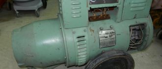
It consists of a cigar-shaped body, on which a block with control equipment, control elements (batch switch and rheostat regulator) and contacts for connecting electrodes is mounted on top, and an asynchronous motor and generator are mounted inside on one rotating shaft, separated by a cooling fan.
There is no direct electrical connection between the generator and the engine . The motor, started from the mains supply, begins to rotate the shaft with which its rotor is connected at high speed.
The generator armature is also mounted on this shaft. As a result of the rotation of the armature, an alternating current is induced in its windings, which is converted into direct current by the collector and supplied to the welding terminals.
PSO-500 is a single-station mobile type welding converter. It is mounted on a three-wheeled trolley. The amount of welding current produced by PSO-500 can reach 300 or 500 A, depending on the jumper connecting one of the terminals to the series winding of the generator.
The output current is adjusted manually using a vernier connected to a rheostat (resistance changing device). The current is monitored using a built-in ammeter.
The numerical index in the marking - 350, 500, 800, 1000 - means the maximum direct current with which this converter is designed to work. Some models, using a vernier, can be configured to produce a welding current greater than the rated one, but operation in this mode is fraught with overheating and rapid failure of the device.
Advantages
Like any other equipment, welding converters (which historically appeared much earlier than inverters) have certain advantages, and at the same time they carry a number of certain inconveniences. Their advantages include:
- high welding current - for some models, in particular PSO-500 and PSG-500, it reaches 500 A, there are also more powerful devices;
- unpretentiousness at work;
- insensitivity to input voltage changes;
- relatively high reliability with qualified maintenance;
- good maintainability, ease of service.
The current that these devices are capable of delivering can weld very thick seams, about 10-30 mm. This is another important advantage due to which welding converters are used.
Flaws
However, the design features also determine the main disadvantages of welding converters, due to which they have been replaced by inverters, at least in the domestic sphere (welding work in small businesses, in the country, in the garage). First of all this:
- large dimensions and weight (it can reach half a ton or more);
- low efficiency;
- increased electrical hazard;
- noisy operation;
- need for service.
The principle of their operation - the transition of electrical energy into mechanical energy and vice versa - implies large energy costs for shaft rotation. This results in very high power consumption, making the device unprofitable for “home” use.
In addition, the presence of parts rotating at high speed reduces the reliability of the machine. The bottleneck of the cooking converter, like the electric motor itself, is the ball bearings on which the shaft is mounted.
They need periodic inspection and oil changes 1-2 times a year. It is also necessary to monitor the condition of the commutator and current collector brushes.
By increased electrical danger we mean the fact that before starting welding work, the converter must be grounded; according to the rules, its connection to the network must only be carried out by an electrician.
Classification
Welding converters are classified according to various parameters. Including the number of welding stations (single and multi-station) and the type of drive (from an electric motor or, for example, from an internal combustion engine). According to their design, they can be stationary or mobile, in a single or double housing.
Converters also differ in the shape of the output characteristic. For many types of work, this classification is decisive. Based on the shape of the output characteristic, welding converters are divided into devices that produce a falling or rigid characteristic (the latter are also capable of producing a flat falling characteristic).
Elements of the electrical circuit of inverter devices
The welding inverter device consists of the following basic elements:
- rectifier for alternating current coming from a regular electrical network;
- an inverter unit assembled on the basis of high-frequency transistors (such a unit is a generator of high-frequency pulses);
- a transformer that lowers the high-frequency voltage and increases the high-frequency current;
- high-frequency alternating current rectifier;
- working shunt;
- electronic unit responsible for controlling the inverter.
Whatever characteristics a particular model of inverter device has, the principle of its operation, based on the use of a high-frequency pulse converter, remains unchanged.
Example of an inverter circuit diagram (click to enlarge)
