When designing and manufacturing bent parts from pipes and rods, the task of determining the length of the development - the length of a straight workpiece before the start of the bending process - always arises.
Continuing the topic...
I present the calculation in Excel of the development length of parts made of round rods and pipes.
The calculation program is written according to the classic strength of strength formula! Practical results will differ slightly from calculated values due to a number of factors, which were already mentioned in the article on sheet metal bending (link to this article in the previous paragraph). However, the program presented below will ensure accuracy when bending a pipe for the manufacture of a prototype.
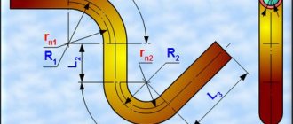
Below this text the figure shows the calculation diagram.
The radii of the neutral layers of each of the curved sections are calculated using the formula:
r ni
=((4* R i 2 - D 2 ) 0.5 +(4* R i 2 - d 2 ) 0.5)/4
The neutral layer is the surface closest to the center of the bending radius of the pipe material during bending compresses, and beyond which from the center of the bending radius it stretches.
The length of curved sections when bending a pipe is determined by the formula:
li =π *α i /180*r ni
Here the angle α i
must be in degrees.
The total length of the development is calculated by summing the lengths of straight and curved sections:
L
= ∑( L i + l i )
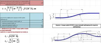
Program for calculating the length of development in Excel when bending pipes.
To perform calculations we use MS Excel.
You can use the Calc spreadsheet processor from the free Apache OpenOffice or LibreOffice .
Initial data:
Let's assume that in the example under consideration, the part consists of three straight and two curved sections (as in the diagram above).
1.
We write down the outer diameter of the pipe
D
in millimeters
to cell D4: 57,0
2.
the value of the internal diameter of the pipe
d
in millimeters
to cell D5: 50,0
Attention!!!
If the development length of a solid round bar is calculated, then d =0!
3.
the length of the first straight section
L 1
in millimeters
to cell D6: 200,0
4.
the axial bend radius of the first curved section
R 1
in millimeters
to cell D7: 300,0
5.
the bending angle of the first curved section
α 1
in degrees
to cell D8: 90,0
6.
the length of the second straight section of the part
L 2
in millimeters
to cell D9: 100,0
7.
the axial bend radius of the second curved section
R 2
in millimeters
to cell D10: 200,0
8.
the bending angle of the second curved section
α 2
in degrees
to cell D11: 135,0
9.
the length of the third straight section of the part
L 3
in millimeters
to cell D12: 300,0
10-15.
Entering the initial data into Excel for our example is complete. We leave cells D13…D18 empty.
The program allows you to calculate the development of parts containing up to five straight sections and up to four curved ones. Bending a pipe with a large number of sections requires a slight modernization of the program to calculate the development.
Calculation results:
16.
the length of the first curved section
L 1
in millimeters
in cell D20: =IF(D7=0;0;PI()*D8/180*((4*D7^2-$D$4^2)^0.5+(4*D7^2-$D$5 ^2)^0.5)/4) =469,4
17.
the length of the second curved section
L 2
in millimeters
in cell D21: =IF(D10=0;0;PI()*D11/180*((4*D10^2-$D$4^2)^0.5+(4*D10^2-$D$5 ^2)^0.5)/4) =467,0
18-19.
Since in the example under consideration there are no third and fourth curved sections, then
in cell D22: =IF(D13=0;0;PI()*D14/180*((4*D13^2-$D$4^2)^0.5+(4*D13^2-$D$5 ^2)^0.5)/4) =0,0
in cell D23: =IF(D16=0;0;PI()*D17/180*((4*D16^2-$D$4^2)^0.5+(4*D16^2-$D$5 ^2)^0.5)/4) =0,0
20.
The total length of the part development
L
in millimeters is summed up
in cell D24: =D6+D9+D12+D15+D18+D20+D21+D22+D23 =1536,3
The development length of the curved pipe was calculated using MS Excel.
When are calculations needed?
Parameters are calculated using a calculator or using online programs
It is important to know what area the pipeline surface should have in the following cases.
- When calculating the heat transfer of a “warm” floor or register. Here the total area is calculated, which transfers heat emanating from the coolant to the room.
- When heat losses are determined along the way from a source of thermal energy to heating elements - radiators, convectors, etc. To determine the number and size of such devices, we need to know the amount of calories that we must have, and it is derived taking into account the development of the pipe.
- To determine the required amount of thermal insulation material, anti-corrosion coating and paint. When constructing highways that are kilometers long, accurate calculations save the enterprise considerable money.
- When determining a rationally justified profile section that could ensure maximum conductivity of the water supply or heating network.
Information
After completing the installation of pipe communications, above-ground or underground pipelines, the need arises to paint the pipes. This is done to avoid corrosion and destruction of steel pipelines. The online calculator will help you calculate the area of the pipe, as well as the paint consumption for painting the pipe surface. The program will quickly and without errors determine the area to be painted on the pipe; you just need to enter the available dimensions into the calculator menu bar.
Calculator functions for calculating pipes
The pipe area calculator for painting is an online program consisting of the following blocks:
- two lines for entering pipe sizes;
- additional function “Count paint consumption”;
- two lines of output of finished calculation results;
- reference information with a pipe sketch, formula and explanation of symbols.
The pipe painting calculator allows you to calculate:
- pipe surface area;
- required amount of paint.
In addition, the finished result can be saved as a PDF file or printed with one click.
How the calculator works
To get a ready-made calculation of the pipe area and paint consumption, you need to enter the following data in the program menu lines:
- indicate the outer diameter, in mm;
- indicate the length, in meters;
To obtain the amount of paint required, you need to tick the “Calculate paint consumption” box and:
- indicate paint consumption based on the average consumption rate (i), in g/m2;
After this, the calculator will automatically produce the finished result: calculation of the pipe area in square meters; the amount of paint required in grams.
IMPORTANT! In order to use the pipeline for a long time and without repairs, several rules must be followed: remove rust, degrease the surface of the pipe, apply at least two layers of paint: base primer and main finish. You can avoid all these procedures, with the exception of degreasing, and use a special 3in1 rust paint, which includes primer, paint and a rust converter.
Pipe (water and gas) is a type of rolled metal, a long hollow welded product of round cross-section. It is used for water and gas pipelines, heating systems, as well as for the manufacture of parts for water and gas pipelines.
Source
Determination of pipe parameters
Cross-sectional area
The pipe is a cylinder, so calculations are not difficult
The cross-section of a round profile is a circle, the diameter of which is determined as the difference in the outer diameter of the product minus the wall thickness.
In geometry, the area of a circle is calculated as follows:
S = π R^2 or S= π (D/2-N)^2, where S is the internal cross-sectional area; π – number “pi”; R – section radius; D—outer diameter; N is the thickness of the pipe walls.
Note! If in pressure systems the liquid fills the entire volume of the pipeline, then in a gravity sewer only part of the walls is constantly wetted. In such collectors, the concept of open cross-sectional area of the pipe is used.
External surface
The surface of the cylinder, which is the round profile, is a rectangle. One side of the figure is the length of the pipeline section, and the second is the circumference of the cylinder.
Pipe development is calculated using the formula:
S = π DL, where S is the pipe area, L is the length of the product.
Inner surface
This indicator is used in the process of hydrodynamic calculations, when the surface area of the pipe that is constantly in contact with water is determined.
When determining this parameter, you should consider:
- The larger the diameter of the water pipes, the less the flow rate depends on the roughness of the walls of the structure.
On a note! If pipelines with a large diameter are characterized by a short length, then the value of the wall resistance can be neglected.
- In hydrodynamic calculations, the roughness of the wall surface is given no less importance than its area. If water flows through a water pipe that is rusty inside, then its speed is less than the speed of the liquid that flows through a relatively smooth polypropylene structure.
- Networks that are mounted from non-galvanized steel are characterized by a variable internal surface area. During operation, they become covered with rust and overgrown with mineral deposits, which narrows the lumen of the pipeline.
Important! Pay attention to this fact if you want to make cold water supply from steel material. The throughput of such a water supply system will be halved after ten years of operation.
The calculation of the pipe development in this case is made taking into account the fact that the internal diameter of the cylinder is determined as the difference between the external diameter of the profile and the double thickness of its walls.
As a result, the surface area of the cylinder is determined by the formula:
S= π (D-2N)L, where the indicator N is added to the already known parameters, which determines the wall thickness.
The workpiece development formula helps to calculate the amount of thermal insulation required
To know how to calculate the development of a pipe, it is enough to remember the geometry course that is taught in middle school. It’s nice that the school curriculum is used in adult life and helps solve serious problems related to construction. Let them be useful for you too!
Calculation of workpiece dimensions during bending
Let's consider a situation that often arises in bending production. This is especially true for small workshops that make do with small and medium-sized mechanization. By small and medium mechanization I mean the use of manual or semi-automatic sheet benders. The operator sums up the length of the shelves, obtains the total length of the workpiece for the required product, measures the required length, cuts and... after bending, receives an inaccurate product. Errors in the dimensions of the final product can be quite significant (depending on the complexity of the product, the number of bends, etc.). This is because when calculating the length of the workpiece, it is necessary to take into account the thickness of the metal, the bending radius, and the coefficient of the position of the neutral line (K-factor). This is exactly what this article will focus on.
So let's get started.
To be honest, calculating the dimensions of the workpiece is not difficult. You just need to understand that you need to take into account not only the lengths of the shelves (straight sections), but also the lengths of the curved sections resulting from plastic deformations of the material during bending.
Moreover, all the formulas have long been derived by “smart people”, whose books and resources I constantly indicate at the end of the articles (from there, if you wish, you can get additional information).
Thus, in order to calculate the correct length of the workpiece (part development), which ensures the required dimensions after bending, it is necessary, first of all, to understand which option we will use to make the calculation.
I remind you:
So if you want shelf surface A
without deformations (for example, for the location of holes), then you calculate according to
option 1
.
If the overall height of shelf A
, then, without a doubt,
option 2
is more suitable.
Option 1 (with allowance)
We will need:
a) Determine the K-factor (see Reference);
c) Sum up the lengths of these segments. In this case, the lengths of straight sections are summed up without change, and the lengths of curved sections are summed up taking into account the deformation of the material and the corresponding displacement of the neutral layer.
So, for example, for a workpiece with one bend, the formula will look like this:
Where X1
– length of the first straight section,
Y1
– length of the second straight section,
φ
– external angle,
r
– internal bending radius,
k S
– metal thickness.
Thus, the calculation progress will be as follows..
Y1 + BA1 + X1 + BA2 +
..etc
The length of the formula depends on the number of variables.
Option 2 (with deduction)
In my experience, this is the most common calculation option for rotary beam bending machines. Therefore, let's look at this option.
We also need:
a) Determine the K-factor (see table).
b) Divide the contour of the bending part into elements, which are straight segments and parts of circles;
Here it is necessary to consider a new concept - the outer boundary of bending.
To make it easier to imagine, see the picture:
The outer boundary of the bend is this imaginary dotted line.
So, to find the length of the deduction, you need to subtract the length of the curved section from the length of the outer boundary.
Thus, the formula for the length of the workpiece according to option 2:
Where is Y2
,
X2
– flanges,
φ
– external angle,
r
– internal bending radius,
k
– neutral line position coefficient (K-factor),
S
– metal thickness.
Deduction from us ( BD
), as you understand:
Outer bending boundary ( OS
):
And in this case, it is also necessary to calculate each operation sequentially. After all, the exact length of each shelf is important to us.
The calculation scheme is as follows:
(Y2 – BD1 / 2) + (X2 – (BD1 / 2 + BD2 / 2)) + (M2 – (BD2 / 2 + BD3 /2)) +
.. etc.
Graphically it will look like this:
And also, the amount of deduction ( BD
) during sequential calculations, it is necessary to calculate correctly.
That is, we are not just cutting two. First we count the entire BD
, and only after that we divide the resulting result in half.
I hope that I did not offend anyone with this remark. I just know that mathematics is forgotten and even basic calculations can be fraught with surprises that no one needs.
That's all. Thank you all for your attention.
When preparing the information, I used: 1. Article “BendWorks. The fine-art of Sheet Metal Bending” Olaf Diegel, Complete Design Services, July 2002; 2. Romanovsky V.P. “Handbook of Cold Forging” 1979; materials from the English-language resource SheetMetal.Me (section “Fabrication formulas”, link: https://sheetmetal.me/formulas-and-functions/)
Calculation of the development length of a part
A simplified sweep is calculated as follows:
Let's say there is a part like in the picture.
We calculate the total sweep along the MIDDLE line... something like this:
23.5+47+63+35+47+18.5=284 mm.
Then we count the bends. We get 6 gibs. Each bend reduces the length of the development by approximately the thickness of the material. Our part is made from 3 mm sheet. From the resulting total development length (284 mm), subtract 3x6 = 18 mm.... We get the sweep length 284-18 = 266. The figure is quite empirical, but allows you to calculate the size quite accurately.
It is also necessary to take into account the following limitation - the minimum distance between bends or from the bend to the edge of the workpiece must be at least 15 mm. This is a technological limitation of the sheet bending machine. It could be less, but it needs to be discussed. There are other restrictions, but we will decide this together.
Calculation of developments of parts from sheets at angle N°
Now we will look at the development of a part whose surfaces are bent at any angle relative to each other. There is nothing complicated here. Regular geometry. School program. The length of the sweep Lp is equal to the sum of the lengths of straight sections and the length of the arc connecting these sections. The calculation is carried out along the average line of the material thickness. Here you need to know that the average line is not just the thickness of the material divided by two. This is a neutral layer between stretched and compressed fibers, the length of which does not change when bending. The radius of the midline is determined by the formula
Rav = r + t * K
where coefficient K
determined from the table. It depends on the ratio of the internal bending radius and the material thickness r/t
Lр = L1 + L2 + Larcs
Larc = pi * G/180 * Ravg
How we see r/t
(in the figure r/s) is equal to 1.5. Selecting 1.5 from table we get
K = 0.441
Well, here we have a drill. This file is xl Calculation of sweep
You can download directly from the site. It will calculate everything itself. You just need to enter the dimensions. If you want to see how the formulas work, remove the protection from the sheet. There is no password.
Sincerely, Larisa Starykh.
Bracket dimensions: a=70mm; b=80mm; c=60mm; t=4mm. Workpiece development length L=a+b+c+0.5t=70+80+60+2=212mm.
Example 2.
Calculate the length of the development of the square blank with internal rounding (Fig. c).
We divide the square according to the drawing into sections. Substituting their numerical values (a=50mm; b=30mm; t=6mm; r=4mm) into the formula L=a+b+3.14/2(r+t/2),
we get
L=50+30+3 .14/2(4+6/2)=50+30+1.57x7=0.99=91mm.
We divide the bracket into sections, put their numerical values (a=80mm; h=65mm; c=120mm; t=5mm; r=2.5mm) into the formula L=a+h+c+3.14(r+t/ 2),
we get
L=80+65+120+3.14(2.5+5/2)=265+15.75=280.75mm.
By bending this strip into a circle, we get a cylindrical ring, and the outer part of the metal will stretch out somewhat, and the inner part will shrink. Consequently, the length of the workpiece will correspond to the length of the center line of the circle, passing in the middle between the outer and inner circles of the ring.
Workpiece length L=3.14xD
. Knowing the diameter of the middle circumference of the ring and substituting its numerical values into the formula, we find the length of the workpiece:
L=3.14x108=339.12mm
. As a result of preliminary calculations, it is possible to produce a part of the established dimensions.
21.Bending of sheet and strip metal parts
Bending of a rectangular bracket made of strip steel is performed in the following order:
determine the length of the workpiece development by adding the length of the sides of the staple with an allowance for one bend equal to 0.5 of the strip thickness, i.e. L=17.5+1+15+1+20+1+15+1+17.5= 89mm;
mark the length with an additional allowance for processing the ends of 1 mm per side and cut off the workpiece with a chisel;
straighten the cut-out workpiece on the stove;
sawn to size according to the drawing;
cause bending risks;
clamp the workpiece in a vice between the squares - jaws at the level of the mark and bend the end of the bracket with blows with a hammer (the first bend);
rearrange the workpiece in a vice, clamping it between a square and a bar - a mandrel longer than the end of the clamp;
bend the second end, making a second bend;
remove the workpiece and remove the block - mandrel;
mark the length of the legs at the curved ends;
put a second square on the vice and, placing the same block - a mandrel - inside the bracket, but in a different position, clamp the bracket in the vice at the level of the marks;
bend the first and second legs, make the fourth and fifth bends of the first and second legs;
check and straighten the fourth and fifth bends along the square;
remove the burrs on the edges of the staple and file the ends of the legs to size.
Bending a double square in a vice
is carried out after marking, cutting out
ki of the workpiece, straightening on the plate and filing along the width to a given size. At the end of bending, the ends of the square are filed to size and the burrs are removed from the sharp edges.
The clamp is flexible.
After calculating the length of the workpiece and marking it at the bending points, clamp the mandrel in a vice in a vertical position. The diameter of the mandrel must be equal to the diameter of the clamp hole. The final formation of the clamp is carried out using the same mandrel with a hammer, and then on a correct plate.
Bending the ear with round pliers.
Eyelet with a rod made of thin wire
tread with the help of round nose pliers. The length of the workpiece should be 10...
15mm more than required according to the drawing. After finishing the work, remove the excess end with pliers.
Bushing bending.
Let's say you need to bend a cylindrical bushing from strip steel on round mandrels.
First, determine the length of the workpiece. If the outer diameter of the sleeve is 20mm and the inner diameter is 16mm, then the average diameter will be 18mm. Then the total length of the workpiece is determined by the formula L = 3.14x18 = 56.5 mm.
22. Mechanization of bending works.
Profiles (strip, sectioned metal) with different radii of curvature are bent on three- and four-roller machines. The machine is preliminarily set up by positioning the upper roller relative to the two lower ones by rotating the handle. When bending, the workpiece must be pressed by the upper roller to the two lower ones.
Profiles with a large bending radius are produced on three-roller
machines in several transitions.
Four roller machine
consists of a frame, two drive rollers that feed the workpiece, and two pressure rollers. Such machines are used for bending profiles along a circular or spiral arc.
23. Pipe bending and flaring
Pipes are bent by hand and mechanized methods, in hot and cold conditions, with and without fillers. The bending method depends on the diameter and material of the pipe, and the bending angle.
Hot pipe bending
used for diameters greater than 100mm.
When hot bending with filler, the pipe is annealed, marked, and one end is closed with a wooden or metal plug.
The diameters of the plugs (plugs) depend on the internal diameter of the pipe. For pipes of small diameters, plugs are made of clay, rubber or hardwood; they are made in the form of a conical plug with a length equal to 1.5...2 pipe diameters, with a taper of 1:10. For pipes of large diameters, plugs are made of metal.
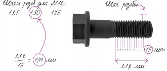
The length L (mm) of the heated section of the pipe is determined by the formula L=ad/15
, where a is the pipe bending angle, degrees; d – outer diameter of the pipe, mm; 15 – constant coefficient (90:6=15; 60:4=15; 45:3=15).
When bending hot pipes, wear gloves. The pipes are heated with blowtorches in forges or the flame of gas burners until they have a cherry red color. It is recommended to heat the pipes once, since repeated heating degrades the quality of the metal.
Cold pipe bending
performed using various devices. The simplest device for bending pipes with a diameter of 10...15 mm is a plate with holes, in which pins are installed in appropriate places to serve as stops during bending.
Pipes of small diameters (40 mm) with large radii of curvature are cold bent using simple hand tools with a fixed frame. Pipes with a diameter of up to 20 mm are bent in a device that is attached to the workbench using a hub and a plate.
Bending of copper and brass pipes.
Copper or brass pipes to be cold bent are filled with molten rosin, molten stearin (paraffin) or molten lead.
Copper pipes
, subject to bending in a cold state, are annealed at 600...700 degrees and cooled in water. The filler when bending copper pipes in a cold state is rosin, and in a heated state it is sand.
Brass pipes
, subject to bending in a cold state, are first annealed at 600...700 degrees and cooled in air.
The fillers are the same as when bending copper pipes. 0
Unfortunately, this is a real model, already produced.
The customer does not require such angles to be made, they just need to repeat what has already been done. Copy.
Problems…
1) 5 mm - I don’t have such bending tools and I haven’t seen anything similar except for a special tool for a stamp.
2) Laser cut into an acute angle or even with your hole to a diameter of 1 mm. At least there should be a diameter no less than the thickness of the sheet. Or there will be cracks.
3) When bending, the inner layers will be squeezed out and the corner will be deformed due to the impossibility of a complete fit. There are also the bends of the walls, which should bend second; what the matrix will be there, one can only guess. Or you need to select knives with 45° bevels at the edges and exact lengths, taking into account the gaps to the edges.
Counter question: how will you make it?
2. Without knowing the material, it is indecent to talk about cracks.
3. The corners will still be slightly deformed, but the author didn’t say anything about beauty. What does the matrix have to do with it? Set the punches with gaps; no bevels are needed.
Such a part is manufactured without significant effort and special equipment. tool.
2. Material duralumin, 1.5 mm.
3. Beauty is not particularly important. The main thing is to repeat.
1. Take the bending radius with reserve and ensure the accuracy of the development is the “right way”. Either everything should be in line with the technology, or then don’t bother with development and let the model be a model. The rest is from the evil one.
2. It is decent, decent to warn about frequently encountered problems and indicate their existence. Otherwise, with the silence of the designers, they will not get closer to technology.
3. The matrix, but since we are not discussing manufacturing technology, then okay.
P.S. I myself am a designer, but I don’t discuss such things with a technologist. Unnecessary returns of drawings from the technologist and conversations greatly lengthen the time cycle for a product to enter the market. Therefore, it is better to go into the workshop once again and try to make something yourself. 80% of possible questions will disappear immediately. And a beautiful part lasts longer and works better.
I don’t do flexible training myself. But I will definitely check the manufacturing process. To be sure whether it is possible or not.
Why don’t you want to do the corners like that?
and it’s more convenient to make and the metal won’t tear and the bending radius can be kept to a minimum and there are no immediate problems for welding or polymerizing
Yes, I think 1.5 mm duralumin should not be torn too much. It needs to be similar to the original. Therefore, we abandoned this method of relieving tension.
STATE COMMITTEE OF THE RUSSIAN
FEDERATION FOR HIGH SCHOOL
TOLYATTI POLYTECHNIC INSTITUTE
Department of Materials Science and Metal Technology
§ 26. General information
Bending is a method of processing metal by pressure, in which a workpiece or part thereof is given a curved shape. Bench bending is performed with hammers (preferably with soft strikers) in a vice, on a plate or using special devices. Thin sheet metal is bent with mallets, wire products with a diameter of up to 3 mm are bent with pliers or round nose pliers. Only plastic material is subject to bending.
Bending parts is one of the most common metalworking operations. The production of flexible parts is possible both manually using support tools and mandrels, and on bending machines (presses).
The essence of bending is that one part of the workpiece is bent relative to the other at a given angle. This happens in the following way: a bending force acts on a workpiece, freely lying on two supports, which causes bending stresses in the workpiece, and if these stresses do not exceed the elastic limit of the material, the deformation obtained by the workpiece is elastic, and upon removal of the load, the workpiece takes on its original view (straightens).
However, when bending, it is necessary to ensure that the workpiece, after removing the load, retains its given shape, therefore the bending stresses must exceed the elastic limit and the deformation of the workpiece in this case will be plastic, while the inner layers of the workpiece are subjected to compression and shortened, the outer layers are subject to tension and their length increases . At the same time, the middle layer of the workpiece - the neutral line - experiences neither compression nor tension, and its length before and after bending remains constant (Fig. 93a). Therefore, determining the dimensions of profile blanks comes down to calculating the length of straight sections (flanges), the length of shortening of the blank within the radius or the length of the neutral line within the radius.
When bending parts at right angles without rounding on the inside, the bend allowance is taken from 0.5 to 0.8 of the thickness of the material. By adding the length of the inner sides of the square or staple, we get the length of the workpiece.
Example 1
. In Fig. 93, c, d shows a square and a bracket with right internal angles.
Dimensions of the square (Fig. 93, c): a = 30 mm, b = 70 mm, t = 6 mm. Development length
L = a + b + 0.5t = 30 + 70 + 3 = 103 mm.
Bracket dimensions (Fig. 93, d): a = 70 mm, b = 80 mm, c = 60 mm, t = 4 mm. Reaming length of the staple blank
L = 70 + 80 + 60 + 2 = 212 mm.
We divide the square according to the drawing into sections. We substitute their dimensions a = 50 mm, b = 30 mm, t = 6 mm, r = 4 mm into the formula
L = a + b + π/2(r + t/2)
Then we get:
L = 50 + 30 + 3.14/2(4 + 6/2) = 50 + 30 + 1.57⋅7 = 90.99 91 mm.
We divide the bracket into sections, as shown in the drawing. Their dimensions: a = 80 mm, h = 65 mm, c = 120 mm, t = 5 mm, r = 2.5 mm.
L = a + h + c + π(r + t/2) = 80 + 65 + 120 + 3.14(2.5 + 5/2),
hence,
L = 265 4 + 15.75 = 280.75 mm.
By bending this strip into a circle, we obtain a cylindrical ring, with the outer part of the metal stretching somewhat and the inner part shrinking. Consequently, the length of the workpiece will correspond to the length of the center line of the circle, passing in the middle between the outer and inner circles of the ring.
Workpiece length
Knowing the diameter of the middle circumference of the ring and substituting its numerical value into the formula, we find the length of the workpiece:
L = πD = 3.14 108 = 339.12 mm.
As a result of preliminary calculations, it is possible to produce a part of the established dimensions.
During the bending process, significant stresses and deformations occur in the metal. They are especially noticeable when the bending radius is small. To prevent cracks from appearing in the outer layers, the bending radius should not be less than the minimum permissible radius, which is selected depending on the thickness and type of material being bent (Fig. 95).
The formula for the development length of a pipe blank helps to calculate the surface area or cross-section of a pipeline. The calculation is based on the size of the future route and the diameter of the planned structure. In what cases such calculations are required and how they are done, this article will tell you.
Guidelines for laboratory work.
TOGLYATTI 2006
UDC 669.017.3
Development of a technological process for manufacturing parts using sheet stamping: Method. Instructions / Compiled by Gurchenkov N.I., RUsanov E.V., Afanasyev E.V. – Tolyatti: TolPI, 1996.
Individual tasks are presented and the procedure for developing a technological process and selecting a sample for cutting and forming by sheet stamping is given.
For special students 1201, 1202, 1205, 1206, 1501, 1502, 1505, 1705, 1808, 2103.
Compiled by: Gurchenkov N.I., Rusanov E.A., Afanasyev E.V.
Scientific editors: Doctor of Technical Sciences, Professor Tikhonov A.K.,
Doctor of Physical and Mathematical Sciences, Professor Vyboishchik M.A.
Approved by the editorial and publishing section of the methodological council of the institute.
Tolyatti Polytechnic Institute, 1996.
Goal of the work
Development of a technological process for manufacturing parts using sheet stamping.
APPLIANCES, EQUIPMENT, MATERIALS,
TUTORIALS.
- Explosive machine RM-10.
Stamp for cutting blanks.
Bending stamp.
Metal scissors.
Calipers.
BASIC SHEET OPERATIONS
STAMPINGS.
Cold sheet stamping is a method of producing flat and three-dimensional thin-walled products from sheets, strips or tapes using dies on presses or without their use (pressless stamping). It is characterized by high productivity, stability of quality and accuracy, large savings in metal, low cost of manufactured products and the possibility of full automation.
The main operations of sheet stamping are separation and forming. As a result of separation operations, one part of the workpiece is separated from another along a given contour.
Separation operations include:
a) cutting - separation of one part of the workpiece relative to another along an open contour;
b) cutting – separation of one part of the workpiece from another along a closed external contour;
c) punching – the formation of through holes in the workpiece.
As a result of form-changing operations, the deformed part of the workpiece changes its shape and size.
Form-changing operations include:
a) bending – turning a flat workpiece into a curved product;
b) drawing - turning a flat workpiece into hollow products;
c) straightening - straightening the uneven surface of the product between the smooth and shaped surfaces of the upper and lower parts of the dies;
d) flanging - the formation of a bead along the internal or external contour of a sheet blank.
In table Appendix 1-4 shows the most common materials used for cold sheet stamping, as well as their mechanical properties.
Calculation of the workpiece for bending.
To calculate the length of the workpiece (reamer), which ensures that after bending the part of the given dimensions is obtained, it is necessary: a) to divide the contour of the stamped part (on the side projection) into elements that are straight segments and segments that are part of a circle;
b) determine the position of the neutral layer based on the thickness of the part (a layer that retains its length unchanged after bending);
c) sum up the length of straight sections without changing, and the lengths of curved sections – taking into account the deformation of the material and the corresponding displacement of the neutral layer.
The length of the workpiece development is determined by the formula:
where L 3 is the length of the workpiece before bending, mm.,
– length of straight sections of the bending part, mm.,
– length of curved sections, mm.
Bending of sheet material is a process of elastoplastic deformation that occurs differently on both sides of the bent workpiece. Compressed fibers are located on the inside of the bend zone, and stretched fibers are located on the outside.
Between the stretched and compressed fibers (layers) of the metal there is a neutral layer 00 (Fig. 1) which, undergoing bending, does not change its original length.
The neutral layer at r/S ≥ 5 coincides with the average thickness of the sections line 00 of the bent workpiece and at r/S
The length of the neutral line of curved sections at the bending angle (in radians) is determined by the formula:
(2)
In our case, the bending is carried out at an angle Ψ = 90°, therefore,
(3)
Radius of the neutral layer when bending rectangular workpieces:
ρ = r + xS, (4)
where: r – internal bending radius, mm;
x – neutral layer displacement coefficient (Appendix, Table 5);
S – workpiece thickness, mm.
After the calculations, make a sketch of the part with dimensions.
Determination of the dimensions of the workpiece during bending is carried out as a development of the part, with the lengths of straight sections and the lengths of curves calculated from the neutral layer being summed up. Such calculations do not present significant difficulties. In practice, when bending particularly complex parts, it is recommended to obtain their development experimentally, since it is not always possible to accurately calculate it theoretically.
There are two main cases of bending: 1) along a curve of a certain radius; 2) at a rounding angle at r
Bending along a curve of a certain radius.
To determine the length of the workpiece, you can use the method of unwrapping a part, based on the fact that the neutral line retains its original dimensions during bending and is located in places of curves at a distance x
0 s
from the inside of the product
(Fig. 2.4).
Therefore, to determine the length of the blank of a complex part, one should sum the length of the straight sections of the bent product with the length of the rounded sections, calculated from the neutral layer.
For a part with one bend at an angle, the length of the workpiece is determined by the formula
, (2.13)
where l 1, l 2 – length of straight sections of the bent product, mm;
l
0
- length of the neutral layer of the rounded section,
mm
;
r
— radius of curvature,
mm
;
Bending angle, degrees;
x
0
is a coefficient that determines the position of the neutral layer.
For a part with several angles, the length of the workpiece is determined by the formula
Rice. 2.4 Calculation of workpiece length
For small elastoplastic deformations (when bending workpieces with a relative radius of curvature r
/ s >5
), it is assumed that the neutral layer passes through the middle of the thickness of the strip
p(p 0 ) = p cf
, that is, its position is determined by the radius of curvature
p = r + s / 2
.
A x 0
is found by the formula:
For significant plastic deformations, which occurs when bending workpieces with a relative radius of curvature, bending is accompanied by a decrease in the thickness of the material and a displacement of the neutral layer towards the compressed fibers. In these cases, the radius of curvature of the neutral deformation layer should be determined by the formula:
where is the thinning coefficient of the material (the thickness of the material after bending, mm).
The thinning coefficient during bending depends on the type of material, the relative radius of the bend and the bending angle. The distance of the neutral layer from the inner surface of the bent workpiece when bending wide strips is determined by the formula
The values of the coefficients and x
about
for bending are given in reference books.
Bending at an angle without rounding.
When bending at an angle without roundings or with roundings of very small radius ()
, which is accompanied by a significant thinning of the metal at the bend points, to determine the size of the workpiece (Fig. 2.5) before bending AB and after bending AVG, they use the mass equality method.
Fig.2.5 Calculation of workpiece length
In practice, the following formula is used:
, (2.20)
where L is the length of the workpiece;
The amount of increase (allowance) of material to form an angle.
Typically, this value, depending on the hardness and thickness of the material, is taken equal to each angle. Moreover, the softer the material, the smaller the increase, and vice versa.
The length of the workpiece for n right angles can be determined by the formula:
During sequential bending. When bending corners at the same time, bending is accompanied by stretching of the material in the middle and at the ends of the sections. In this case, the stretching of the material occurs over most of the bent workpiece, so that here the formation of corners occurs partially due to the stretching of the material of the straight sections. Therefore, for these cases, it is recommended to take half the increase in the length of the workpiece than with sequential bending, that is, accept.
Elements of the workpiece located in the deformable zone and adjacent to the inner surface of the bent part (from the punch side) are subject to compression, and those adjacent to the outer surface (from the matrix side) are subject to tension. Between the stretched and compressed fibers there is a neutral line whose length does not change (Drawing 106).
Crap. 106
Neutral line radius
R in mm (drawing 106) is determined by the formula
where r is the bending radius, mm;
s - material thickness mm;
x is a coefficient, the value of which depends on the ratio r/s (Table 48).
Table 48
| r/s ratio | ||||||||||
| Coefficient x | 0,323 | 0,340 | 0,356 | 0,367 | 0,379 | 0,389 | 0,400 | 0,413 | 0,421 | 0,426 |
| r/s ratio | 10 or more | |||||||||
| Coefficient x | 0,441 | 0,445 | 0,463 | 0,469 | 0,477 | 0,780 | 0,485 | 0,490 | 0,495 | 0,500 |
When curling hinges (loops), due to the presence of external friction forces that prevent deformation, the coefficient x is determined from the table. 48a.
Table 48a
| r/s ratio | ||||
| Coefficient x | 0,56 | 0,54 | 0,52 | 0,51 |
Development length
bending part L p in mm (Fig. 107) is determined by the formula
L р =(l 1 +l 2 +l 3 +. . .)+ π / 180 (φ 1 R 1 +φ 2 R 2 +φ 3 R 3 +. . .) (47)
where l 1; l 2 ; l 3 - straight sections, mm;
φ 1; φ 2; φ 3 — bending angles, degrees;
R1; R2; R 3 - radii of the neutral line, determined by formula (46).
Crap. 107
When bending materials with a thickness of more than 3 mm at an angle of 90° with a bending radius r≤s, the radius of the neutral line R, calculated according to formula (46), must be adjusted to the value R 1 (Fig. 108), based on the condition of material integrity and mating in points a and a 1 of a curved section of radius R 1 with straight lines a-a and a 1 -a 1 passing through the middle of the thickness s. In section C-C 1, the dotted line shows the outer contour in the calculation without taking into account the thinning of the material. Due to thinning during bending, the thickness s 1 in this area is less than the original s.
Crap. 108
The values of R 1 for the radius of the adjusted neutral line and the length of the arc aba 1 should be calculated using the formulas
R is determined by formula (46); r—bending radius, mm; other designations are shown in Fig. 108.
Elements for determining the dimensions of the reamers of commonly used bent parts are given in Table. 49.
Table 49
Note
:
- y, y 1, y 2 - values that take into account the change in the development length when bending at an angle of 90°. For material thickness up to 2.5 mm, they are taken according to the table. 50, and with a thickness of 3 mm or more at r
- x - coefficient, taken according to the table. 48a.
Table 50
Table 50a
Example
. Determine the length of the development for the part shown in Fig. 109.
Crap. 109
According to table.
49 L р =l+l 1 + y, where l and l 1 are the lengths of the straight sections of the bent part;
y - find from the table. 50a
At s=4 mm and r= 3.5 mm
L p =50+40+ 1.22=91.22 mm.
If one-sided tolerances are specified in the working drawing of a part, then to calculate the length of the development, these tolerances must be recalculated to two-sided ones, while maintaining the specified tolerance field. In this case, the nominal dimensions of the part must also be recalculated (Fig. 110).
Crap. 110
In table 51 and 52 provide formulas for calculating the sweep length
bent parts with different initial data on the working drawing and different forms of mating.
Table 51
Note
: x - coefficient, determined from table. 48.
The sweep calculation will be performed in MS Excel.
In the drawing of the part the following is specified: the value of the internal radius R
, angle
a
and length of straight sections
L1
and
L2
. Everything seems simple - elementary geometry and arithmetic. In the process of bending the workpiece, plastic deformation of the material occurs. The outer (relative to the punch) metal fibers are stretched, and the inner ones are compressed. In the middle of the section there is a neutral surface...
But the whole problem is that the neutral layer is not located in the middle of the metal section! For reference: the neutral layer is the surface of the arrangement of conditional metal fibers that do not stretch or compress when bent. Moreover, this surface is (sort of) not the surface of a circular cylinder. Some sources suggest that it is a parabolic cylinder...
I am more inclined to trust the classical theories. For a rectangular section according to the classical strength of material, the neutral layer is located on the surface of a circular cylinder with radius r
.
r
= s / ln (1+ s / R )
Based on this formula, a program was created for calculating the development of sheet parts made of steel grades St3 and 10…20 in Excel.
In cells with light green and turquoise fill we write the original data. In a cell with a light yellow fill, we read the calculation result.
1.
We record the thickness of the sheet blank
s
in millimeters
to cell D 3: 5,0
2.
the length of the first straight section
L 1
in millimeters
to cell D 4: 40,0
3.
the internal bend radius of the first section
R 1
in millimeters
to cell D 5: 5,0
4.
the bend angle of the first section
a 1
in degrees
to cell D 6: 90,0
5.
the length of the second straight section of the part
L 2
in millimeters
to cell D 7: 40,0
6.
That’s it, the result of the calculation is the length of the part’s development
L
in millimeters
in cell D 17: =D4+IF(D5=0;0;PI()/180*D6*D3/LN ((D5+D3)/D5))+ +D7+IF(D8=0;0;PI ()/180*D9*D3/LN ((D8+D3)/D8))+D10+ +IF(D11=0;0;PI()/180*D12*D3/LN ((D11+D3)/D11 ))+D13+ +IF(D14=0;0;PI()/180*D15*D3/LN ((D14+D3)/D14))+D16 =91.33
L
= ∑ ( Li +3.14/180* ai * s / ln (( Ri + s )/ Ri )+ L ( i +1))
Using the proposed program, you can calculate the development length for parts with one bend - corners, with two bends - channels and Z-profiles, with three and four bends. If you need to calculate the development of a part with a large number of bends, then the program can be very easily modified to expand its capabilities.
An important advantage of the proposed program (unlike many similar ones) is the ability to set different bending angles and radii at each step
.
Does the program produce the “correct” results? Let's compare the obtained result with the results of calculations using the methodology outlined in the “Handbook of Mechanical Designer” by V.I. Anuriev and in the “Die Designer’s Handbook” by L.I. Rudman. Moreover, we will take into account only the curved section, since, I hope, all rectilinear sections are considered the same.
Let's check the example discussed above.
“According to the program”: 11.33 mm – 100.0%
“According to Anuriev”: 10.60 mm – 93.6%
“According to Rudman”: 11.20 mm – 98.9%
In our example, let’s double the bending radius R
1
to 10 mm. Once again we will make the calculation using three methods.
“According to the program”: 19.37 mm – 100.0%
“According to Anuriev”: 18.65 mm – 96.3%
“According to Rudman”: 19.30 mm – 99.6%
Thus, the proposed calculation method produces results that are 0.4%...1.1% more than “according to Rudman” and 6.4%...3.7% more than “according to Anuriev”. It is clear that the error will decrease significantly when we add straight sections.
“According to the program”: 99.37 mm – 100.0%
“According to Anuriev”: 98.65 mm – 99.3%
“According to Rudman”: 99.30 mm – 99.9%
Perhaps Rudman compiled his tables using the same formula that I use, but with the error of a slide rule... Of course, today it’s the twenty-first century, and it’s somehow not convenient to scour the tables!
In conclusion, I will add a “fly in the ointment”. The length of the sweep is a very important and “subtle” point! If the designer of a bent part (especially a high-precision part (0.1 mm)) hopes to accurately determine it by calculation and the first time, then he hopes in vain. In practice, a lot of factors will interfere with the bending process.
– direction of rolling, tolerance on metal thickness, thinning of the section at the bending point, “trapezoidal section”, temperature of the material and equipment, presence or absence of lubrication in the bending zone, mood of the bender... In short, if the batch of parts is large and expensive,
check the length with practical experiments scans on several samples
. And only after receiving a suitable part, cut the blanks for the entire batch. And for the manufacture of blanks for these samples, the accuracy provided by the development calculation program is more than enough!
Calculation programs “according to Anuriev” and “according to Rudman” in Excel can be found on the Internet.
I look forward to your comments, colleagues.
For the REST - you can download it just like that...
The topic is continued in the article about.
Read about calculating the development when bending pipes and rods.
Let's consider a situation that often arises in bending production. This is especially true for small workshops that make do with small and medium-sized mechanization. By small and medium mechanization I mean the use of manual or semi-automatic sheet benders. The operator sums up the length of the shelves, obtains the total length of the workpiece for the required product, measures the required length, cuts and... after bending, receives an inaccurate product. Errors in the dimensions of the final product can be quite significant (depending on the complexity of the product, the number of bends, etc.). This is because when calculating the length of the workpiece, it is necessary to take into account the thickness of the metal, the bending radius, and the coefficient of the position of the neutral line (K-factor). This is exactly what this article will focus on.
So let's get started.
To be honest, calculating the dimensions of the workpiece is not difficult. You just need to understand that you need to take into account not only the lengths of the shelves (straight sections), but also the lengths of the curved sections resulting from plastic deformations of the material during bending.
Moreover, all the formulas have long been derived by “smart people”, whose books and resources I constantly indicate at the end of the articles (from there, if you wish, you can get additional information).
Thus, in order to calculate the correct length of the workpiece (part development), which ensures the required dimensions after bending, it is necessary, first of all, to understand which option we will use to make the calculation.
I remind you:
So if you want shelf surface A
without deformations (for example, for the location of holes), then you calculate according to
option 1
.
If the overall height of shelf A
, then, without a doubt,
option 2
is more suitable.
Option 1 (with allowance)
We will need:
c) Sum up the lengths of these segments. In this case, the lengths of straight sections are summed up without change, and the lengths of curved sections are summed up taking into account the deformation of the material and the corresponding displacement of the neutral layer.
So, for example, for a workpiece with one bend, the formula will look like this:
Where X
1
is the length of the first straight section,
Y 1
is the length of the second straight section,
φ
is the external angle,
r
is the internal bending radius,
k S
is the thickness of the metal.
Thus, the calculation progress will be as follows..
Y1 + BA1 + X1 + BA2 +
..etc
The length of the formula depends on the number of variables.
Option 2 (with deduction)
In my experience, this is the most common calculation option for rotary beam bending machines. Therefore, let's look at this option.
We also need:
a) Determine the K-factor (see table).
b) Divide the contour of the bending part into elements, which are straight segments and parts of circles;
Here it is necessary to consider a new concept - the outer boundary of bending.
To make it easier to imagine, see the picture:
The outer boundary of the bend is this imaginary dotted line.
So, to find the length of the deduction, you need to subtract the length of the curved section from the length of the outer boundary.
Thus, the formula for the length of the workpiece according to option 2:
Where Y
2
,
X 2
– flanges,
φ
– external angle,
r
– internal bending radius,
k
– neutral line position coefficient (K-factor),
S
– metal thickness.
Deduction from us ( BD
), as you understand:
Outer bending boundary ( OS
):
And in this case, it is also necessary to calculate each operation sequentially. After all, the exact length of each shelf is important to us.
The calculation scheme is as follows:
(Y2 – BD1 / 2) + (X2 – (BD1 / 2 + BD2 / 2)) + (M2 – (BD2 / 2 + BD3 /2)) +
.. etc.
Graphically it will look like this:
And also, the amount of deduction ( BD
) during sequential calculations, it is necessary to calculate correctly.
That is, we are not just cutting two. First we count the entire BD
, and only after that we divide the resulting result in half.
I hope that I did not offend anyone with this remark. I just know that mathematics is forgotten and even basic calculations can be fraught with surprises that no one needs.
That's all. Thank you all for your attention.
When preparing the information, I used: 1. Article “BendWorks. The fine-art of Sheet Metal Bending” Olaf Diegel, Complete Design Services, July 2002; 2. Romanovsky V.P. “Handbook of Cold Forging” 1979; materials from the English-language resource SheetMetal.Me (section “Fabrication formulas”, link:
When designing and manufacturing bent parts from pipes and rods, the task of determining the length of the development - the length of a straight workpiece before the start of the bending process - always arises.
Continuing the topic...
I present the calculation in Excel of the development length of parts made of round rods and pipes.
The calculation program is written according to the classic strength of strength formula! Practical results will differ slightly from calculated values due to a number of factors, which were already mentioned in the article on sheet metal bending (link to this article in the previous paragraph). However, the program presented below will ensure accuracy when bending a pipe for the manufacture of a prototype.
Below this text the figure shows the calculation diagram.
The radii of the neutral layers of each of the curved sections are calculated using the formula:
r ni
=((4* R i 2 - D 2 ) 0.5 +(4* R i 2 - d 2 ) 0.5)/4
The neutral layer is the surface closest to the center of the bending radius of the pipe material during bending compresses, and beyond which from the center of the bending radius it stretches.
The length of curved sections when bending a pipe is determined by the formula:
li =π *α i /180*r ni
Here the angle α i
must be in degrees.
The total length of the development is calculated by summing the lengths of straight and curved sections:
L
= ∑( L i + l i )