The tool holder is one of the most important blocks of lathes, used to secure the cutting tool. There are many modifications to the design of such a unit, intended for use in various conditions. In addition, universal tool holders for lathes are produced, which can also be used for other metal-cutting equipment. The quality of metalworking of a workpiece largely depends on the accuracy of the cutter holder.
Design and purpose of the tool holder
The tool holder is a separate unit fixed with a bolt connection, used for fastening a metalworking tool. Significantly simplifies work with workpieces and allows for maximum bore holes. Tool holders are equipped with machine blocks that move the cutter.
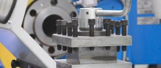
At the top of caliper 1, on the centering collar, there is a tetrahedral head. On one side there is a cone-shaped retainer 5 with a spring 4, on the reverse side there is a ball retainer 17 with a plug on the thread 12 and a spring 15.
A flange 5 is attached to the top of the head 13 with bolts. On the middle finger 16 inside the head there is a fist 11, which has end teeth, as well as a ratchet clutch 10, which is pressed against the end of the fist by a spring 8. The clutch easily moves along the slots of the sleeve 9, pressed into the handle 7.
Handle 7 is used to release, rotate, install and secure the head. Release is carried out by turning the handle along the thread counterclockwise. Together with the handle, the fist 11, connected to it through the teeth of the ratchet 10, also moves. When the head is released under the influence of the bevel of the fist 11, the latch itself is raised on the tab of the latch 3, the knuckle 11 turns the head, resting the wall of the cutout against the pin 14. The ball 17 is raised at the same time . In the final stage of reversal, the locking ball falls into the next socket, preliminarily securing the head.
When the handle 7 is turned in the opposite direction, the fist 11 releases the latch 3, while it falls into slot 2 and finally secures the head. The wall of the cutout rests against the pin and stops the fist 11. Subsequent rotation of the handle 7 leads to the pressing of the ratchet 10 upward with the beveled end teeth. After turning the handle, the head and cutting tool are finally secured.
Design Features
The chuck consists of a set of collets and a clamping nut. The collet can be clamping or feeding, as well as retractable or fixed, and other modifications.
So, the clamping collet has the following varieties:
- Feeding the workpiece;
- One-piece clamping;
- Separate clamping.
The first collet consists of a steel sleeve with 3 cuts, forming a kind of petal with the ends in the center and springy. The hole should be such that the workpiece is clamped tightly. The feed collet is screwed onto a rotating rod, which feeds the workpiece through a certain mechanism. Under the influence of elasticity, the petals sit tightly on the workpiece . Frictional force increases adhesion during processing.
A solid collet is a sleeve with springy petals when exposed to pressure. Three-lobe modifications are used for working parts with a diameter of less than 3 mm, four-lobe modifications are used for workpieces with diameters from 3 to 80 mm, then six-lobe modifications should be used. The grip increases by reducing the size of the slots as the collet is pulled into the chuck.
The split option should be used for parts of the smallest diameter. The cams are moved apart using springs. The kit may also include replacement inserts.
Conditional division of holders for cutters
Lathe holders are divided according to several parameters.
According to the type of execution, holders are:
- with replaceable blocks;
- with an axis of rotation.
According to the location of the axis, the latest models are divided into:
- horizontal (along the spindle);
- vertical (at an angle of 90° to the spindle).
By way of changing position:
- mechanical;
- electromechanical;
- hydraulic;
- with servo drive.
By the number of places for installing cutters:
- two-position, allowing you to simultaneously fix a pair of incisors;
- four-position, allowing the simultaneous installation of four units of cutting devices on the machine.
Fastening the tool in the tool holder can be done in several ways:
- through a wedge block;
- VDI – fastening with one wedge bolt from the edge of the holder disk;
- TDC – fixation in a hole at a remote diameter of the disk.
In addition, according to the type of construction, tool holders are divided into:
- simple (“soldier”);
- rotary;
- quick-change cassette tool holders;
- universal adapters.
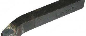
Simple tool holder
Tool holders for a lathe of a conventional “soldier” design are equipped with a special spherical gasket, which allows you to quickly install the required cutter. The cutting angle and height position are changed by rotating the gasket. The tool is secured in the tool holder with one bolt.
The advantage of this design is the ability to quickly install the cutter. The disadvantage is that the entire load is carried by a single bolt, so it must be tightened tightly and the degree of fastening must be constantly checked before turning on the machine.
When working with a machine with a tool holder of this type, you should avoid over-tightening the bolt, as there is a high probability of stripping the thread. To repair the holder, it is enough to replace the bolt, bore the holes to a different size, or install bushings with internal threads in the resulting gap.
To increase strength, bolts are made of high-strength steel, cemented to a depth of 0.6–0.8 and hardened. As a result, the bolt corresponds to a hardness grade of 50–60 HRC and is resistant to rupture.
Tool holders of the “soldier” design were often installed on Soviet-made machines. Now they have been transferred to the category of obsolete and are installed on models of light machine tools. Such tool holders hold a single tool that requires periodic change.
Rotary
The most common tool holders in lathes are those that allow you to place 4 cutters at once.
The machine is prepared in advance to perform several consecutive jobs without the need to replace the cutter. The maximum effect from installing a rotary tool holder in the machine is obtained when it is necessary to process parts of complex geometric shapes. Tool holders of this design look like a revolver. The main part is a disk with holes made through it, located at the same distance from each other. The holes contain slotted bushings in which the machine cutters are fixed. Thanks to the use of bushings, the cutters are installed without spacers - the cutting tool can be replaced quickly. Tool holders have spring devices that allow you to bore holes to great depths, cut internal threads, and use the machine for other work that requires high precision.
The machines currently produced also have rotary tool holders that carry up to 12 cutters. They are especially effective on CNC machines, where productivity increases significantly. Quick tool fixation and increased reliability are ensured by an electromechanical drive.
In some lathes, for example, the TC series, rotary tool holders have different design features. The tool is clamped using hardened bars or a lever-wedge device.
Quick change tool holder
If the machine is used at home for small volumes of various jobs, the cutters need to be changed frequently.
For minimal labor and time losses, it is recommended to install a quick-change tool holder with replaceable cassettes. The holders are secured in this way: an axle is screwed into the upper part of the caliper, which serves as a clamp for the tool holder. The holder is pressed on top with a nut. Included with such devices is a plate that allows you to raise the cutter higher if necessary.
The cassette is fastened using a wedge strip.
Universal adapter
Universal type cutter holders (adapters) allow you to install tools with larger dimensions on the machine than those provided for by the design.
When using small-sized machines, sometimes it becomes necessary to work with large cutters. The holder available on the machine does not allow the placement of tools of other sizes, which is why large cutters have to be ground down. To avoid boring, a special tool holder-adapter is installed on the machine, allowing you to work with tools of various sizes.
How to choose a collet chuck
The first thing to consider when choosing such a chuck is its attachment to the spindle. You can install it directly on the spindle, using a suitable adapter or by screwing it onto the thread.
Then we look at the dimensions of the flange. The diameter of the connection band or the parameters of the Morse taper will help here. If you do not know these indicators, then you will not be able to select the required cartridge, and therefore, there will be no opportunity for high-quality operation of your tools
And, finally, the number of jaws in the tool. Depending on the purpose of the tools, they can have from two to six jaws in a set. You can also choose a tool made of hard or soft alloy, for certain types of work, with different technical characteristics.
Recommendations for use
The tool holder belongs to the main blocks of the machine and is fixed to it by means of a bolted connection.
The use of the device is especially effective when high-precision boring is required. Their design must be reliable and highly durable. It is equally important to install the cutter correctly, because the accuracy of metalworking noticeably decreases when even a small backlash appears. The tool holder on the lathe is used to attach the cutter vertically and horizontally. Inaccurate fixation in height is considered the main cause of defects and processing defects. When turning, the cutter must be placed so that its working part is on top of the centers of the machine. When boring, the cutter should be installed at the bottom of the centering plane.
The tool holder on the universal machine is placed on the upper slide of the support. There are also rotary and transverse devices located there, and the support itself is placed on the longitudinal slide of the frame. All these units together allow you to move the cutter in all directions and rotate it along the axis, which makes it possible to use the maximum number of metalworking operations.
The holder for a heavy type roughing machine is placed on an auxiliary slide. This is explained by the too large dimensions of the cross slide: moving them manually is extremely difficult.
Types of chucks
Depending on the work to be done and the purpose of the machines, all clamping products can be classified into the following types:
- Lever;
- Collet;
- Drilling, also known as quick-clamping;
- Wedge and hydraulic chucks;
- Three- and four-cam;
- Thermal cartridges and membrane.
Self-clamping drill chucks are used on universal or special lathes . Their use allows the clamping force to be transferred with less torque compared to drill chucks.
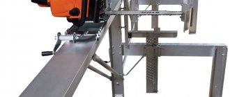
DIY holder design options
Despite the variety of designs, you can make a tool holder yourself from materials available in any garage or home workshop.
Homemade tool holders used for “garage” work are not subject to increased requirements for the accuracy of tool fastening, and you can save a significant amount for other needs. Video:
What tool holder is installed on your machine? Have you tried to make it yourself at home? Please share your opinion and experience in the comments.