Information about the manufacturer of the 6T12-1 cantilever milling machine
The manufacturer of the 6T12-1 series of universal milling machines is the Gorky Milling Machine Plant , founded in 1931.
The plant specializes in the production of a wide range of universal milling machines, as well as milling machines with DRO and CNC, and is one of the most famous machine-tool enterprises in Russia.
Since 1932, the Gorky Milling Machine Plant has been producing machine tools and is an expert in the development and production of various metal-cutting equipment.
Products of the Gorky Milling Machine Plant GZFS
- 6G605
double-spindle longitudinal milling machine, 500 x 1600 - 6M12P
vertical cantilever milling machine, 320 x 1250 - 6M13P
vertical cantilever milling machine, 400 x 1600 - 6M82
universal horizontal milling machine, 320 x 1250 - 6M82G
horizontal cantilever milling machine, 320 x 1250 - 6М82Ш
universal cantilever milling machine, 320 x 1250 - 6M83
universal horizontal milling machine, 400 x 1600 - 6M83G
horizontal cantilever milling machine, 400 x 1600 - 6М83Ш
horizontal cantilever milling machine, 400 x 1600 - 6N12
vertical cantilever milling machine, 320 x 1250 - 6N13P
vertical cantilever milling machine, 400 x 1600 - 6N82
horizontal cantilever milling machine, 320 x 1250 - 6N82G
horizontal cantilever milling machine, 320 x 1250 - 6Р12, 6Р12Б
vertical cantilever milling machine, 320 x 1250 - 6Р13, 6Р13Б
vertical cantilever milling machine, 400 x 1600 - 6Р13Ф3
vertical cantilever milling machine with CNC, 400 x 1600 - 6Р82
universal horizontal milling machine, 320 x 1250 - 6R82G
horizontal cantilever milling machine, 320 x 1250 - 6Р82Ш
universal cantilever milling machine, 320 x 1250 - 6Р83
universal horizontal milling machine, 400 x 1600 - 6R83G
horizontal cantilever milling machine, 400 x 1600 - 6Р83Ш
universal cantilever milling machine, 400 x 1600 - 6T12-1
vertical cantilever milling machine, 320 x 1250 - 6T12
vertical console-milling machine, vertical, 320 x 1250 - 6T12F20
vertical cantilever milling machine with CNC, 320 x 1250 - 6T13
vertical cantilever milling machine, 400 x 1600 - 6T13F20
vertical cantilever milling machine with CNC, 400 x 1600 - 6T13F3
vertical cantilever milling machine with CNC, 400 x 1600 - 6T82
universal horizontal milling machine, 320 x 1250 - 6T82-1
universal horizontal milling machine, 320 x 1250 - 6T82G
horizontal cantilever milling machine, 320 x 1250 - 6Т82Ш
universal cantilever milling machine, 320 x 1250 - 6T83
universal horizontal milling machine, 400 x 1600 - 6T83-1
universal horizontal milling machine, 400 x 1600 - 6T83G
universal horizontal milling machine, 400 x 1600 - 6Т83Ш
universal cantilever milling machine, 400 x 1600 - 6605
double-spindle longitudinal milling machine, 500 x 1600 - 6606
three-spindle longitudinal milling machine, 630 x 2000 - GF2171
vertical milling machine with CNC and ASI, 400 x 1600
6T12-1 vertical cantilever milling machine. Purpose and scope
6T12-1 vertical cantilever milling machine has been produced since 1985 and replaced the outdated 6P12 model in production.
In 1985, the Gorky Milling Machine Plant (GZFS) began production of cantilever milling machines of the 6t12-1 series. Machines of the 6t12-1 series are a further improvement of similar machines of the P series (6P12, 6P13).
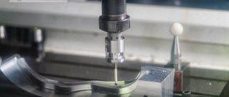
The vertical cantilever milling machine 6T12-1 is designed for milling all kinds of parts from various materials. It is used in single and serial production.
6T12-1 cantilever milling machine differs from the 6T13-1 machine in the installed power of the main movement and feed motors, the dimensions of the working surface of the table and the amount of table movement.
6T12-1 milling machine can process vertical and horizontal planes, grooves, corners, frames, gears, etc.
6T12-1 vertical cantilever milling machine can operate in three modes:
- Automatic - In automatic mode, the machine operates at various automatic cycles.
- Jog — In jog mode, adjustment movements of the table are made. Marking work is possible.
- Manual - In the manual universal mode, the machine operates using working feeds, rapid movements, as well as manual movements from the flywheels and handle.
Design features of the 6T12-1 milling machine
The technological capabilities of machines can be expanded through the use of overhead milling, dividing and slotting heads, and a round rotary table.
There is a device for limiting the gap in the screw pair for the longitudinal movement of the table, individual lubrication of the vertical movement screw, which increases its durability and reduces the lifting force of the console.
Additional devices have been introduced to protect against flying chips and emulsions .
The rigidity of the machine has been increased due to the rectangular guides of the bed and console.
There is automatic spindle braking in operating mode and during emergency shutdown.
Automated lubrication of components increases their durability and reduces maintenance time.
The rotating spindle head of the machine is equipped with a mechanism for manual axial movement of the spindle sleeve, which allows processing of holes whose axis is located at an angle of up to ±45° to the working surface of the table.
The drive power and high rigidity of the machines allow the use of cutters made of high-speed steel, as well as tools equipped with plates made of hard and super-hard synthetic materials.
Tool fastening is mechanized . The cross-feed screw is located along the axis of the cutter, which increases processing accuracy. The technological capabilities of the machine can be expanded with the use of a dividing head, a rotary round table and other devices.
The ability to configure the machine for various semi-automatic and automatic cycles allows you to organize multi-machine maintenance and use the machine to perform various jobs in continuous production.
The machine can be supplied to countries with temperate, cold and tropical climates.
Machine accuracy class - N according to GOST 8-82E
The main design advantages of the machines:
- mechanized tool fastening in the spindle;
- proportional feed deceleration mechanism;
- a device for periodically adjusting the size of the gap in the longitudinal feed screw pair;
- safety clutch protecting the feed drive from overloads;
- braking of the horizontal spindle when stopping using an electromagnetic clutch;
- protection device against flying chips.
Main technological advantages of the machines:
- various automatic machine operation cycles;
- wide range of spindle speeds and table feeds;
- high drive power;
- high rigidity;
- reliability and durability.
- The technological capabilities of machine tools can be expanded by using a dividing head, a round rotary table and other devices.
The machines are produced in various versions according to voltage and frequency of the supply network. Spare parts are supplied.
The main differences between the 6T12-1 (1985) and 6T12 (1991) milling machines
- Overhang (distance from the spindle axis to the bed guides): 6t12-1 - 350 mm, 6t12 - 380 mm
- Transverse movement of the table: 6t12-1 - 270 mm, 6t12 - 320 mm
- Distance from the edge of the table to the frame: 6t12-1 - 70..340 mm, 6t12 - 70..390 mm
The working space of the machine model 6t12 is 50 mm larger along the X, Y axes than that of the machine 6t12-1.
Modifications of console-milling machines of the “T” series
Various modifications and specialized machines have been developed based on the “T” series machines:
- 6T12 - 6T12-27, 6T12-29, 6T12-30
- 6Т13 - 6Т13-27, 6Т13-29, 6Т13-30
- 6T82G - 6T82G-27 (GF2793), 6T82G-29, 6T82G-30
- 6T83G - 6T83G-27 (GF2797), 6T83G-29, 6T83G-30
- 6T82 - 6T82-27 (GF2794), 6T82-29, 6T82-30
- 6T83 - 6T83-27 (GF2798), 6T83-29, 6T83-30
- 6T82Sh - 6T82Sh-27, 6T82Sh-29, 6T82Sh-30, 6T82Sh-35, 6T82Sh-36, 6T82Sh-37, 6T82Sh-38
- 6T83Sh - 6T83Sh-27, 6T83Sh-29, 6T83Sh-30, 6T83Sh-35, 6T83Sh-36, 6T83Sh-37, 6T83Sh-38
Modifications 6T...-27 have a 100 mm increased distance from the spindle axis (end) to the working surface of the table and a mechanism for proportional (2 times) slowdown of the working feed.
Russian and foreign analogues of the 6T12-1 (6T13-1) machine
FSS350MR, FSS450MR - 315 x 1250, 400 x 1250 - manufacturer Gomel Machine-Tool Plant
VM127M - (400 x 1600) - manufacturer Votkinsk Machine-Building Plant GPO, Federal State Unitary Enterprise
6D12, 6K12 - 320 x 1250 - manufacturer Dmitrov milling machine plant DZFS
X5032, X5040 - 320 x 1320 - manufacturer Shandong Weida Heavy Industries, China
FV321M, (FV401) - 320 x 1350 (400 x 1600) - manufacturer Arsenal JSCo. — Kazanlak, Arsenal AD, Bulgaria
History of production of machine tools by the Gorky plant, GZFS
In 1937
, the Gorky
Milling Machine Plant produced the first cantilever milling machines of the 6B series, models 6B12 and 6B82 , with a work table of 320 x 1250 mm (2nd standard size).
In 1951
6N of cantilever milling machines was launched into production 6N13PR machine received the “Grand Prix” at the world exhibition in Brussels in 1956.
In 1960
6M cantilever milling machines
was launched into production In 1972
6P of cantilever milling machines
was put into production In 1975
year, copying cantilever-milling machines were launched into production:
6Р13К .
In 1978
In 2009, copying cantilever-milling machines
6Р12К-1 , 6Р82К-1 .
In 1985
6T-1 of cantilever milling machines was put into production 6T13-1 , 6T82-1, 6T83-1 and GF2171.
In 1991
6T of cantilever milling machines was put into production
Main technical indicators and advantages
Despite the fact that the presented model has been produced in Russia for more than 30 years, this does not prevent the machine from still creating good competition with more modern models. There are several reasons for this.
For example, the minimum deviation in the location of the treated surface and its shape is explained by the fact that the load-bearing elements have higher rigidity. Also, to increase rigidity, scraped guides with a compatible profile are used.
The spindle supports used by the vertical milling machine are equipped with paired angular contact and double-row roller bearings, which are characterized by increased load capacity. This facilitates power cutting with high quality processing. If standard lubrication is used, and the structural elements themselves have the correct tension, the bearing life will be longer than the amount of time before a major overhaul. To determine the class of bearings, you must read the technical data sheet.
In a screw pair, backlash is eliminated using a specially designed movable nut, which is included in the axial play control mechanism. Bimetallic materials are used in the production of all running nuts. Parts subject to more accelerated wear in areas of friction are produced using steel that is surface hardened with high-frequency heat. Exactly the same heat treatment method is used to strengthen gears. As a result, the equipment operates for a long period of time without the need for maintenance. And when the time comes to complete it, the cost of spare parts will be minimal.
The composition of a centralized effective lubrication system includes two groups. The first includes lubricant for the mechanisms in the console, and the second includes an oil supply system for the mechanisms located in the frame. Each of them, accordingly, provides separate power from its own plunger-type pump.
If the 6t12 1 machine is used every day in two shifts, the overhaul cycle will be at least 11 years. But achieving such performance is only possible if the user complies with operational requirements and primarily mills steel.
Increased drive power reserves, a wide range of speeds and feeds, minimal system compliance - all this contributes to high-performance processing of metal workpieces, which include plates made of STM or high-strength materials.
Achieving additional time savings is made possible thanks to the electromechanical method of fixing the tool. The table itself moves in automatic cycles. The revolutions are switched without sequential passage of steps.
Components
Considering the main characteristics, the basic design advantages of this equipment model are the presence of the following components:
- a device for slowing down the feed speed (the machine uses a proportional circuit);
- a mechanism to protect against metal shavings falling on the operator and others;
- an electromagnetic clutch that effectively brakes the spindle assembly in the horizontal plane;
- clutch to protect the main feed electric motor from overload;
- a device that allows you to adjust the gap in the screw pair (when feeding in the longitudinal direction).
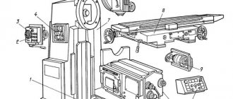
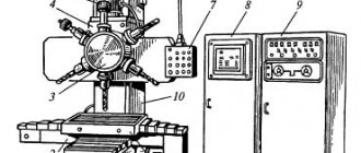
Location of components of the 6T12-1 cantilever milling machine
Location of components of the milling machine 6t12-1
List of components of the cantilever milling machine 6t12-1
- bed
- side remote control
- feed switch mechanism
- spindle gearbox
- rotating head
- electromechanical tool clamping devices
- control cabinet
- table and sled
- feed delay mechanism
- main remote control
- console
- gearbox
Certificate of vertical milling machine 6T12F20-1 with digital display LUMO-61
This instruction manual “Cantilever vertical milling machine with operational program control 6T12F20-1 ” contains information necessary both for the maintenance personnel of this machine and for the employee directly involved in working on this machine. This manual is an electronic version in PDF format of the original paper version. This documentation contains the Passport and Manual (instructions) for the operation of the universal screw-cutting lathe 6T12F20-1 . Contents of this documentation:
GENERAL INFORMATION
MAIN TECHNICAL DATA AND CHARACTERISTICS
Contents of delivery
SAFETY INSTRUCTIONS
COMPOSITION OF THE MACHINE
INSTALLATION PROCEDURE
DEVICE AND OPERATION OF THE MACHINE AND ITS COMPONENTS
Lubrication system
INSTALLATION PROCEDURE
Possible malfunctions and methods for eliminating them
FEATURES OF DISASSEMBLY AND ASSEMBLY DURING REPAIR
Maintenance and repair instructions
Spare parts materials
You can download the passport of the console vertical milling machine 6T12F20-1 (32 sheets) in good quality from the link below. Since this machine is built on the LUMO-61 digital display device, in addition to this passport, documentation on the LUMO-61 control unit is required.
Documentation on the OPU LUMO-61 system. Download for free. (Link is temporarily not working)
You can download the passport of the console vertical milling machine 6T12F20-1 (53 sheets) in good quality from the link below.
Control panels for milling machine 6T12-1
Control panels for milling machine 6T12-1: main -II, side -I
List of controls for the 6T12-1 cantilever milling machine
- Spindle speed indicator
- Button “Move table back, forward, down”
- Switch for selecting the direction of table movement
- Switch “Clamp-Release Tool”
- Button “Move table forward, left, up”
- Spindle Jog button (duplicate)
- Button “Stop table movement”
- Spindle start button
- “Spindle Stop” button (duplicate)
- Emergency Stop button
- Button “Fast table movement” (duplicate)
- Spindle speed shift knob
- —
- Hexagon head rotation
- Spindle sleeve clamp handle
- Key "Move table left"
- "Move table to the right" key
- Key "Stop longitudinal movement of the table"
- Spindle Stop button
- Spindle start button
- Table Clamps
- Switch for switching on the table operating mode “Manual - Mechanical”
- Flywheel for manual longitudinal movement of the table
- Vernier ring
- Limb of the table transverse movement mechanism
- Manual lateral movement of the table
- Manual vertical table movement
- Feed switch mushroom
- Emergency Stop button
- Machine operating mode selection switch
- Slow feed switch
- Button “Fast table movement and cycle start”
- “Stop vertical table movement” key
- "Move table down" key
- Slide Clamps
- "Move table up" key
- Flywheel for manual longitudinal movement of the table (duplicate)
- Key "Stop lateral movement of the table"
- "Move table forward" key
- "Move table back" key
- Spindle sleeve extension flywheel
- Clamping the head on the frame
- Input switch
- Spindle rotation direction switch “Left - Right”
- Cooling pump switch "On - Off"
- Control panel selection switch
- Auto cycle selection switch
- Console Clamp
- Removable handle for manual vertical and transverse movement of the table
- Zero head fixation pin
Automatic control mode
In automatic control mode, the electrical circuit ensures processing of the part in the following cycles:
- a) Simple to the left
- b) Simple to the right
- c) Simple to the left with reverse
- d) Simple to the right with reverse
- e) Pendulum
- f) Horizontal right frame
- g) Horizontal left frame
- i) Vertical right frame
- j) Vertical left frame
When installing additional cams acting on the limit switch SQ9, SQ10, cycles a, b, c, d are converted into jump cycles of the type: high speed, working stroke, high speed, working stroke and so on.
When the switch SA6 is turned on, all cycles are converted into cycles with a slowdown during cutting.
In order to set up the machine for any cycle, it is necessary to place cams on the workpiece, acting on the limit switches SQ3...SQ10. Depending on the processing cycle, move the table to its extreme position; the switch limiting the table travel must be pressed.
Set switch SAZ to automatic control mode, and switch SA7 to the position of the selected cycle. When the machine operates in frame cycles, switch SA7 is set to the “frame” position, and switch SA4 selects the required type of frame; in other cycles, SA4 is set to position “O”.
When setting up the machine for cycles “J” and “K” in the control station, it is necessary to make the following switches according to the modifications given in the circuit diagram:
- a) at terminal terminals 60,116, switch the jumpers connecting terminals 150, 151;
- b) at terminal clamps 68.75, switch the wires marked 152, 153, coming from relays K15 and K19;
- c) at terminal clamps 78, 85, switch the wires marked 154, 155, coming from relays K19 and K15.
To describe the operation of the machine’s electrical circuit in automatic control mode, let’s consider the “simple left with reverse” cycle.
The machine cycle begins with clamping the workpiece, after which the high speed button SB11 is pressed.
When you press the SB11 button, relay K15 is turned on through the normally open contact of the limit switch SQ4.2. Relay K15 with its closing contacts turns on relays K5, K11, K13 (see lines 48, 78, 82).
Relay K5 turns on clutch YC1, time relay KT1 becomes self-powered and prepares the circuits for turning on clutches YC7, YC8, YC9 (see lines 20, 46, 101, 112). Relay K11 turns on the YC7 clutch and becomes self-powered.
The K13 cycle relay with its closing contacts includes the automation relay - K20, relay K4 and KT4. Relays K4 and KT4 ensure that the table drives are turned on, after which the table begins to move at high speed to the left. Relay K20 provides the necessary interlocks in automatic control mode (see lines 35, 72, 80, 97).
When the table moves to the left, the travel switch SQ9 is pressed, which turns off relay K11 with its normally open contact. The YC7 clutch is turned off, and the YC8 clutch is turned on, as a result of which the table switches to the working feed mode. If switch SA6 is set to the “slow feed” mode, then the closing contact of switch SQ9 will turn on relay K12, which will provide a circuit for turning on the slow speed clutch YC9 for the duration of the action of the cam on switch SQ9. After switch SQ9 is released, the table continues to move to the left into cutting feed mode. With further movement of the table, the travel switch SQ3 is pressed, which limits the movement of the table to the left and turns on relay K14 (see lines 47, 84). Relay K14 will turn on the rapid movement of the table to the right (see lines 54, 77). The rapid travel is switched off by the limit switch SQ4, which limits movement to the right. After turning off the high speed, the table overtravels are slowed down and the main drive is turned off by relay contact KT4, after which the table drive is turned off and the main drive is braked. The cycle is over.
The “Simple right with reverse” cycle is similar to that described above.
To obtain jumping cycles, a set of cams is added, which act on switches SQ3 and SQ4, and the circuit works as follows.
When the table moves to the left at the feed speed, switch SQ10 is pressed, the contact of which will turn on relay K17. Relay K17 turns on relay K11, and relay K11 will turn off the feed clutch and turn on the high-speed clutch. The table will continue to move to the left at high speed. As you move to the left, switch SQ9 is pressed again, which will turn off the rapid feed and turn on the working feed. The following diagram is described above.
In the simple cycles “Simple Left” and “Simple Right”, the operation of the circuit fully corresponds to the first part of the reverse cycles. Since the reverse cycle relays K14 and K15 are disabled by switch SA7. then the end of the cycles and shutdown of the drives are carried out by limiting switches for the table travel of the left - SQ3, right - SQ4. Moreover, the shutdown can be made both after the working feed and after the high speed.
To ensure the operation of the machine before the pendulum cycle, the functions of the SQ10 switch have been changed in the circuit and the pendulum cycle relay K16 has been introduced.
The pendulum cycle is activated at any extreme position of the table. When the cycle with rapid movement to the left is turned on, switch SQ9.1 is bypassed by relay contact K5 (see lines 75, 73), and rapid movement turns off switch SQ10.1, after which the table movement switches to working feed mode. Deceleration during penetration is provided by relay contacts K16 and K17 (see line 76). Limitation of table movement in feed mode and reverse to fast speed to the right is provided by switch SQ3. During fast motion to the right, relay contact K6 bypasses switch SQ10.1; turning off high speed and turning on working feed is ensured by switch SQ9.1. Limitation of table movement in working feed mode and reverse to fast speed to the left is provided by switch SQ4. It is preferable to stop the cycle in the extreme positions of the table using buttons SB3 AND SB4.
To ensure the machine operates in frame cycles, relays K18, K19 and switch SA4 are introduced into the circuit.
The beginning of the cycle corresponds to the “Simple to the right with reverse” cycle.
When the working stroke is limited to the right by switch SQ4, relay K15 with its contacts (see lines 59, 68) turns on the working feed forward (down). The forward (down) feed is switched off using the travel limit switches SQ5 (SQ8). At the same time, switches SQ5 (SQ8) turn on the working feed to the left (see lines 48, 49, 50). When the table moves to the left in the feed mode, the travel switch SQ10 is pressed, which with its contact (see lines 91, 95) turns on the relay K19. Relay K19 with its contacts (see lines 47, 60, 67) turns off the feed to the left and turns on the feed back (up). The reverse (upward) feed is turned off by limiting limit switches SQ6 (SQ7), at the same time switches SQ6 (SQ7) turn on relay K18. Relay K18 with its contacts (see lines 93, 94, 95, 74) turns off relay K19, turns on fast movement to the left and provides self-power. The fast travel to the left is switched off using switch sQ3. The cycle is over.
It must be borne in mind that any frame cycle begins with the rapid movement of the table to the right.
Kinematic diagram of the 6T12-1 cantilever milling machine
Kinematic diagram of the 6T12-1 cantilever milling machine
The kinematic diagram is given to understand the connections and interactions of the main elements of the machine. The numbers of teeth (g) of the gears are indicated on the callouts (the asterisk indicates the number of starts of the worm).
The main movement is driven by a flange electric motor through an elastic coupling.
The spindle speed is changed by moving three toothed blocks along the splined shafts.
The gearbox provides the spindle with 18 different speeds.
The feed drive is carried out from a flange electric motor mounted in the console. By means of two three-crown blocks and a movable gear wheel with a cam clutch, the feed box provides 18 different feeds, which are transmitted through a ball safety clutch to the console and then, when the corresponding cam clutch is engaged, to the screws of longitudinal, transverse and vertical movements.
Accelerated movements are obtained when the high-speed clutch is turned on, the rotation of which is carried out through intermediate gears directly from the feed electric motor.
The clutch is interlocked with the working feed clutch, which eliminates the possibility of their simultaneous activation.
Graphs explaining the structure of the machine feed mechanism are shown in Fig. 6 and 7.
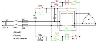
Cooling drive
The cutting tool is cooled by a centrifugal vertical pump with an asynchronous three-phase alternating current electric motor with a squirrel-cage rotor, designated M3. The pump type and electrical characteristics of the motor are given in Table 5.
The pump motor is protected from short circuit currents by fuses FU1, and from short-term overloads by thermal relay FR3. The type and technical characteristics of the FR3 relay are given in Table 7.
The pump is turned on by switch SA2 and the closing contacts of relay KM5 when the spindle drive is turned on.
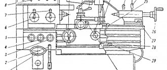
Design of the main components of the 6T12-1 cantilever milling machine
bed
The bed is the base unit on which the remaining components and mechanisms of the machine are mounted.
The frame is rigidly fixed to the base and fixed with pins.
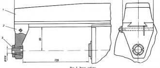
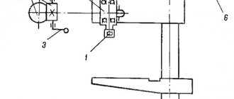
Rotating head of cantilever milling machine 6T12-1
The rotating head (Fig.) is centered in the annular recess of the bed neck and is attached to it with four bolts that fit into a single groove in the bed flange.
The spindle is a two-support shaft mounted in a retractable sleeve. The axial play in the spindle is adjusted by grinding rings 3 and 4. Increased play in the front bearing is eliminated by grinding half rings 5 and tightening the nut.
The adjustment is carried out in the following order:
- the spindle sleeve extends;
- flange 6 is dismantled;
- half rings are removed;
- a screw plug is removed from the right side of the head body;
- through the hole, unscrewing screw 2 unlocks nut 1;
- Nut 1 is locked with a steel rod. By turning the spindle by the nut, the nut is tightened and this moves the inner race of the bearing. After checking the play in the bearing, the spindle is run in at maximum speed. When operating for an hour, the heating of the bearings should not exceed 60° C;
- the size of the gap between the bearing and the spindle collar is measured, after which the half rings 5 are ground to the required amount;
- the half rings are put in place and secured;
- Flange 6 is screwed in.
To eliminate radial play of 0.01 mm, the half rings must be ground by approximately 0.12 mm.
Rotation is transmitted to the spindle from the gearbox through a pair of bevel and a pair of cylindrical gears mounted in the head.
The bearings and gears of the rotary head are lubricated from the frame pump, and the spindle bearings and the sleeve moving mechanism are lubricated by extrusion.
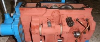
Gearbox
The gearbox is mounted directly in the frame body. The connection of the box to the electric motor shaft is carried out by an elastic coupling, which allows misalignment in the motor installation of up to 0.5-0.7 mm.
The gearbox can be inspected through the window on the right side.
The gearbox is lubricated by a plunger pump (Fig. 9), driven by an eccentric. Pump capacity is about 2 l/min. Oil is supplied to the pump through a filter. From the pump, the oil flows to the oil distributor, from which it is discharged through a copper tube to the pump control eye and through a flexible hose to the rotary head. The gearbox elements are lubricated by splashing oil coming from the holes in the oil distributor tube located above the gearbox.
Gearbox
The gearbox allows you to select the required speed without sequentially passing through intermediate stages.
Rack 19 (Fig. 10), moved by shift handle 18, through sector 15 through fork 22 (Fig. 11) moves the main roller 29 with shift disc 21 in the axial direction.
The shift disk can be turned by the speed indicator 23 through the bevel gears 28 and 30. The disk has several rows of holes of a certain size located against the pins of the racks 31 and 33.
The racks engage in pairs with gear 32. A shift fork is attached to one of each pair of racks. When moving the disk by pressing on the pin of one of the pair, reciprocating movement of the slats is ensured.
In this case, the forks at the end of the disk stroke occupy a position corresponding to the engagement of certain pairs of gears. To eliminate the possibility of hard stop of the gears when switching, the pins of 20 racks are spring-loaded.
Fixation of the dial when choosing a speed is ensured by ball 27, which slides into the groove of sprocket 24.
The spring 25 is adjusted by the plug 26, taking into account the clear fixation of the dial and the normal force when turning it.
Handle 18 (see Fig. 10) is held in the on position by spring 17 and ball 16. In this case, the handle tenon fits into the groove of the flange.
Correspondence of speeds to the values indicated on the indicator is achieved by a certain position of the bevel wheels along the mesh. Correct engagement is established by cores at the ends of the mating tooth and cavity or by setting the pointer to the speed position of 31.5 rpm and the disk with forks to the speed position of 31.5 rpm (for machine models 6T12B the corresponding speed is 50 rpm) . The gap in the engagement of the conical pair should not be more than 0.2 mm, since the disk can rotate up to 1 mm due to this.
The gearbox is lubricated from the gearbox lubrication system by splashing oil.
Main types of work of the vertical milling machine 6T12:
— vertical milling of flat, stepped, curved surfaces
— roughing and finishing operations, the rigidity of the structure allows you to install heavy parts without loss of accuracy and productivity
- milling and drilling work at various angles, due to tilting the head
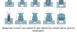
— processing of grooves, wheels, horizontal surfaces of parts
— drilling, boring work, with automatic tool feed, through drilling and against the stop
— thread cutting in semi-automatic mode, fine tuning of feed.
Technical characteristics of the cantilever milling machine 6T12-1
| Parameter name | 6Р12 | 6Р13 | 6Т12-1 | 6Т13-1 |
| Basic machine parameters | ||||
| Table surface dimensions, mm | 1250 x 320 | 1600 x 400 | 1250 x 320 | 1600 x 400 |
| Maximum mass of the workpiece, kg | 250 | 300 | 400 | 630 |
| Maximum longitudinal stroke of the table (X), mm | 800 | 1000 | 800 | 1000 |
| Maximum transverse travel of the table (Y), mm | 250 | 300 | 270 | 340 |
| Maximum vertical travel of the table (Z), mm | 420 | 420 | 420 | 430 |
| Distance from the end of the spindle to the table surface, mm | 30..450 | 30..500 | 30..450 | 70..500 |
| Distance from the spindle axis to the vertical guides of the bed (overhang), mm | 350 | 420 | 350 | 420 |
| Distance from the edge of the table to the vertical guides of the frame, mm | 70..340 | 60..400 | ||
| Spindle | ||||
| Main drive drive power, kW | 7,5 | 10 | 7,5 | 11 |
| Spindle speed, rpm | 40..2000 | 40..2000 | 31,5..1600 | 31,5..1600 |
| Number of spindle speeds | 18 | 18 | 18 | 18 |
| Spindle quill movement, mm | 70 | 80 | 70 | 80 |
| Movement of the spindle quill by one dial division, mm | 0,05 | 0,05 | 0,05 | 0,05 |
| Spindle head rotation angle, degrees | ±45° | ±45° | ±45° | ±45° |
| Spindle end GOST 836-62 | №3 | №3 | ||
| Spindle end GOST 24644-81, row 4, version 6 | 50 | 50 | ||
| Desktop. Submissions | ||||
| Limits of longitudinal and transverse table feeds (X, Y), mm/min | 12,5..1600 | 12,5..1600 | 12,5..1600 | 12,5..1600 |
| Limits of vertical table feeds (Z), mm/min | 4,1..530 | 4,1..530 | 4,1..530 | 4,1..530 |
| Number of table feeds (longitudinal, transverse, vertical) | 22 | 22 | 22 | 22 |
| Speed of fast movements (longitudinal, transverse/vertical) X, Y/ Z, m/min | 4/ 1,330 | 4/ 1,330 | 4/ 1,330 | 4/ 1,330 |
| Movement of the table by one dial division (longitudinal, transverse, vertical), mm | 0,05 | 0,05 | 0,05 | 0,05 |
| Table movement per one revolution of the dial (longitudinal, transverse/vertical), mm | 6/ 2 | 6/ 2 | 6/ 2 | 6/ 2 |
| Maximum permissible cutting force (longitudinal/transverse/vertical), kN | 15/ 12/ 5 | 20/ 12/ 8 | ||
| Machine mechanics | ||||
| Feed stops (longitudinal, transverse, vertical) | Eat | Eat | Eat | Eat |
| Blocking manual and mechanical feeds (longitudinal, transverse, vertical) | Eat | Eat | Eat | Eat |
| Blocking separate feed switching | Eat | Eat | Eat | Eat |
| Spindle braking | Eat | Eat | Eat | Eat |
| Overload safety clutch | Eat | Eat | Eat | Eat |
| Automatic intermittent feed | Eat | Eat | Eat | Eat |
| Electrical equipment and machine drives | ||||
| Number of electric motors on the machine | 4 | 4 | 4 | 4 |
| Main motion electric motor, kW | 7,5 | 10 | 7,5 | 11 |
| Feed drive electric motor, kW | 2,2 | 3,0 | 2,2 | 3,0 |
| Tool clamping motor, kW | 0,18 | 0,18 | ||
| Coolant pump electric motor, kW | 0,125 | 0,125 | 0,12 | 0,12 |
| Total power of all electric motors, kW | 10,0 | 14,3 | ||
| Dimensions and weight of the machine | ||||
| Machine dimensions (length width height), mm | 2305 x 1950 x 2020 | 2560 x 2260 x 2120 | 2280 x 1965 x 2265 | 2570 x 2252 x 2430 |
| Machine weight, kg | 3120 | 4200 | 3400 | 4250 |
- Vertical cantilever milling machines 6T12-1, 6T13-1. Operating manual 6T12-1.00.000 RE,
- Vertical console-milling machines 6T12, 6T13. Operating manual 6T12.00.000 RE,
- Vertical cantilever milling machines 6T12-29, 6T13-29. Operating manual 6T12-29.00.000 RE, 1992
- Cantilever milling machines 6T82G-1, 6T82-1, 6T12-1, 6T82SH-1, 6T83G-1, 6T83-1, 6T13-1, 6T83SH-1. Operating manual for electrical equipment 6T82G.00.000 RE1
- Avrutin S.V. Fundamentals of Milling, 1962
- Avrutin S.V. Milling, 1963
- Acherkan N.S. Metal-cutting machines, Volume 1, 1965
- Barbashov F.A. Milling 1973
- Barbashov F.A. Milling work (Vocational education), 1986
- Blumberg V.A. Milling machine handbook, 1984
- Grigoriev S.P. Practice of coordinate boring and milling work, 1980
- Kopylov Work on milling machines, 1971
- Kosovsky V.L. Handbook of a young milling operator, 1992
- Kuvshinsky V.V. Milling, 1977
- Nichkov A.G. Milling machines (Machinist's Library), 1977
- Pikus M.Yu. A mechanic's guide to repairing metal-cutting machines, 1987
- Plotitsyn V.G. Calculations of settings and adjustments of milling machines, 1969
- Plotitsyn V.G. Setting up milling machines, 1975
- Ryabov S.A. Modern milling machines and their equipment, 2006
- Skhirtladze A.G., Novikov V.Yu. Technological equipment for machine-building industries, 1980
- Tepinkichiev V.K. Metal cutting machines, 1973
- Chernov N.N. Metal cutting machines, 1988
- Frenkel S.Sh. Handbook of a young milling operator (3rd ed.) (Vocational education), 1978
Bibliography:
Related Links. Additional Information
- Milling machines: general information, classification, designation
- Comparative characteristics of cantilever milling machines of the 6N, 6M, 6R, 6T
- Feed box for console milling machines of the 6M : 6M12P, 6M13P, 6M82, 6M83, 6M82Sh, 6M83Sh
- Feed box for console milling machines of the 6P : 6P12, 6P13, 6P82, 6P83, 6P82Sh, 6P83Sh
- Feed box for console milling machines 6T : 6T12, 6T13, 6T82, 6T83, 6T82Sh, 6T83Sh
- Milling machine repair technology
- Adjustment of milling machines
- Friction clutch. Friction shaft. Friction clutches in metal-cutting machines
- Automatic cycles of milling machines (6P12)
- Testing and checking metal-cutting machines for accuracy
- Directory of universal milling machines
- Manufacturers of metal-cutting machines in Russia
- Manufacturers of milling machines in Russia
- Electrical equipment of milling machines 6T12, 6T13, 6T82, 6T82G, 6T82Sh, 6T83, 6T83G, 6T83Sh
- Electrical equipment of milling machines 6P12, 6P13, 6Р82, 6Р82Г, 6Р82Ш, 6Р83, 6Р83Г, 6Р83Ш, 6Р12Б, 6Р13Б
- Electrical equipment of milling machines 6M12P, 6M12PB, 6M13P, 6M13PB, 6M82, 6M82Sh, 6M82GB, 6M83, 6M83Sh
- Electrical equipment of milling machines 6T10, 6T80, 6T80G, 6T80Sh
- Electrical equipment of milling machines 6Р10, 6Р80, 6Р80Г, 6Р80Ш
- Electrical equipment of milling machines 6N10, 6N80, 6N80G, 6N80Sh