At the design stage of power lines, information and control networks, the choice of material and cross-sectional area of the conductor becomes essential. The right engineering solution helps reduce losses, reduce the likelihood of emergency situations, and solve other problems. The relatively low electrical resistance of copper wire explains the popularity of this option. Additional benefits and alternatives are discussed in this publication.
Increasing the cross-section increases the resistance of the conductor to current loads
What does the resistance of a metal depend on?
Electric current, according to the classical definition, is the directed movement of charged particles. Electrons move in metals if a potential difference is created between two points of connection of a power source. This process is hindered by impurities, so conductivity is better in a homogeneous material.
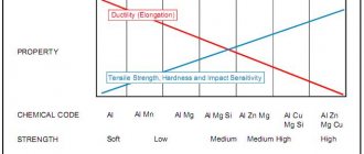
For your information. High-quality current conductors are made from electrical copper, which contains no more than 0.01% of foreign impurities. A slight addition of aluminum (0.02-0.03%) reduces conductivity by 10-11%. With a large route length, energy transmission losses increase significantly.
Vibrational processes of the atoms of the crystal lattice have a negative impact. As the temperature rises, the amplitude of these movements increases, which creates additional obstacles to the movement of charges. To compensate for this phenomenon, resistors are made from special alloys. Properly selected proportions of materials ensure stability of electrical resistance in the designed temperature range.
Calculation of voltage drop on a wire for direct current
Now, using formula (2), we calculate the voltage drop on the wire:
U = ((ρ l) / S) I, (4)
That is, this is the voltage that will drop on a wire of a given cross-section and length at a certain current.
These are the tabular data for a length of 1 m and a current of 1A:
Table 1. Voltage drop on a 1 m copper wire of different cross-sections and a current of 1A:
| S, mm² | 0,5 | 0,75 | 1 | 1,5 | 2,5 | 4 | 6 | 8 | 10 |
| U, B | 0,0350 | 0,0233 | 0,0175 | 0,0117 | 0,0070 | 0,0044 | 0,0029 | 0,0022 | 0,0018 |
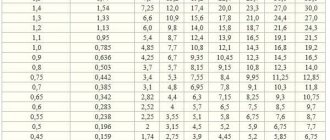
This table is not very informative; it is more convenient to know the voltage drop for different currents and cross sections. Let me remind you that calculations for choosing the wire cross-section for direct current are carried out according to formula (4).
Table 2. Voltage drop for different wire cross-sections (top row) and current (left column). Length = 1 meter
| S,mm² I,A | 1 | 1,5 | 2,5 | 4 | 6 | 10 | 16 | 25 |
| 1 | 0,0175 | 0,0117 | 0,0070 | 0,0044 | 0,0029 | 0,0018 | 0,0011 | 0,0007 |
| 2 | 0,0350 | 0,0233 | 0,0140 | 0,0088 | 0,0058 | 0,0035 | 0,0022 | 0,0014 |
| 3 | 0,0525 | 0,0350 | 0,0210 | 0,0131 | 0,0088 | 0,0053 | 0,0033 | 0,0021 |
| 4 | 0,0700 | 0,0467 | 0,0280 | 0,0175 | 0,0117 | 0,0070 | 0,0044 | 0,0028 |
| 5 | 0,0875 | 0,0583 | 0,0350 | 0,0219 | 0,0146 | 0,0088 | 0,0055 | 0,0035 |
| 6 | 0,1050 | 0,0700 | 0,0420 | 0,0263 | 0,0175 | 0,0105 | 0,0066 | 0,0042 |
| 7 | 0,1225 | 0,0817 | 0,0490 | 0,0306 | 0,0204 | 0,0123 | 0,0077 | 0,0049 |
| 8 | 0,1400 | 0,0933 | 0,0560 | 0,0350 | 0,0233 | 0,0140 | 0,0088 | 0,0056 |
| 9 | 0,1575 | 0,1050 | 0,0630 | 0,0394 | 0,0263 | 0,0158 | 0,0098 | 0,0063 |
| 10 | 0,1750 | 0,1167 | 0,0700 | 0,0438 | 0,0292 | 0,0175 | 0,0109 | 0,0070 |
| 15 | 0,2625 | 0,1750 | 0,1050 | 0,0656 | 0,0438 | 0,0263 | 0,0164 | 0,0105 |
| 20 | 0,3500 | 0,2333 | 0,1400 | 0,0875 | 0,0583 | 0,0350 | 0,0219 | 0,0140 |
| 25 | 0,4375 | 0,2917 | 0,1750 | 0,1094 | 0,0729 | 0,0438 | 0,0273 | 0,0175 |
| 30 | 0,5250 | 0,3500 | 0,2100 | 0,1313 | 0,0875 | 0,0525 | 0,0328 | 0,0210 |
| 35 | 0,6125 | 0,4083 | 0,2450 | 0,1531 | 0,1021 | 0,0613 | 0,0383 | 0,0245 |
| 50 | 0,8750 | 0,5833 | 0,3500 | 0,2188 | 0,1458 | 0,0875 | 0,0547 | 0,0350 |
| 100 | 1,7500 | 1,1667 | 0,7000 | 0,4375 | 0,2917 | 0,1750 | 0,1094 | 0,0700 |
What explanations can be made for this table?
1. in red those cases when the wire will overheat, that is, the current will be higher than the maximum permissible for a given cross-section. I used the table given on SamElektrika: Selecting the cross-sectional area of the wire.
2. Blue color - when the use of too thick wire is economically and technically impractical and expensive. The threshold was taken to be a drop of less than 1 V over a length of 100 m.
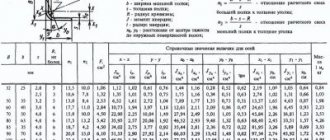
Resistivity of various metals
Table: wire diameter - wire cross-section
To calculate the losses that a certain length of conductor provides, it is convenient to operate with specific parameters. Basic formula for calculating electrical resistance:
R = p*(L/S),
Where:
- L – length in meters;
- S – cross-sectional area, mm2;
- p – specific resistance of a cable made of a certain material, (Ohm*mm sq.)/m.
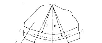
If necessary, the cross-section can be calculated from the diameter ( D ) using the well-known formula from geometry:
S = (π * D2)/4.
If a micrometer is not available, wind the wire around a cylindrical tool (screwdriver, pencil). Next, measure the length of the created coil with a regular ruler and divide the resulting value by the number of turns.
Measuring diameter using improvised means
Copper and aluminum
A minimal amount of impurities is sufficient to significantly change the wire resistance. However, even with a high degree of purification, copper conducts electricity much better than aluminum. Below are the resistivity values of the corresponding materials. Using reference information, it is easy to check losses when choosing cable products to form a route of a certain length:
- pm = 0.0175;
- pa = 0.028.
Other metals
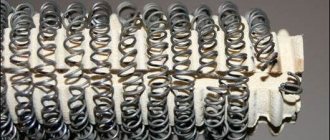
The resistivity of nichrome ranges from 1.04 to 1.42 (Ohm*mm sq.)/meter. The large scatter of parameters is explained by a proportional change in the components of the alloy. Such materials are used to create heating elements, since the integrity of the products is maintained at high temperatures. Given the high resistance of nichrome wire per unit length, this cable is ideal for creating a “warm floor”.
Features of other materials (resistivity Ohm*mm sq.)/m):
- gold (0.023) provides good conductivity and oxidation resistance, but is expensive;
- the limited use of silver (0.015) is also explained by the high price;
- the high melting point (+3,422°C) of tungsten (0.05) allows it to be used for the manufacture of spirals of classic incandescent lamps;
- constantan (0.5) is used to create resistors.
Theory and practice
So, if a person is even a little familiar with the basics of electrical engineering, he should know that the thicker the wire, the lower the resistance.
- Theoretically, this can be compared to a water pipe through which water flows. If the diameter of the pipe is sufficient, then the liquid flows through it without experiencing any hydraulic resistance, and vice versa, a small hole increases the pressure in the pipe, the throughput drops, and the hydraulic resistance increases.
- Also, the flow of electrons can be represented as water trying to flow inside the wire. However, electricity is a completely different nature, and accordingly its physical properties are different.
- What can cause too high resistance? The most common thing is a voltage drop, as a result of which some incandescent lamp will burn dimmer, and some electrical appliance will not be able to start.
- A direct consequence of the passage of a powerful current through a conductor with a sufficiently high resistance will be its overheating.
From the author! One day we connected the welding machine to, well, a very bad extension cord, and after a few minutes of work the wire literally caught fire. Fortunately, a short circuit did not occur, but it was very likely. As is clear, such situations are unacceptable in a residential area.
We recommend proceeding in the following sequence:
- First of all, find out exactly how much load both of your devices create when operating at maximum power. We are interested in current strength, measured in Amperes, or power - Watts.
- You can easily find these parameters in the product data sheets.
- If both devices are powered from the same line, then sum the resulting values.
- Next, use the table, which will allow you to accurately determine the wire cross-section.
The photo shows a table for selecting conductor cross-sections
- As can be seen from the table above, the maximum current for a copper wire with an area of 0.5 should not exceed 11 Amperes.
Advice! Today the use of aluminum wires is not allowed in residential premises. Only copper ones are used.
- In principle, one could limit ourselves to these data, adding some margin, but such tables do not show what the maximum resistance of the wire should be, that is, the length of the conductor is not taken into account. Therefore, for greater accuracy, calculations are indispensable.
Selecting cable cross-sections
For large calculations, you can use a specialized calculator on the help site or appropriate software. The following algorithm is used to sequentially calculate operating parameters using the formulas:
- when transmitting power P = 1,600 W to a connected load in a line with a voltage U = 220 V, direct current (I) is determined as follows: I = P/U ≈ 7.27 A;
- resistance of a copper conductor (in both directions) with a length of 800 m and a cross-section of 2.5 mm square: R = (2*I*p)/S = (2*800*0.0175)/2.5 = 11.2 Ohm ;
- voltage losses in this path: ΔU = (2*L*I)/((1/p)*S) = (2*800*7.27)/((1/0.0175)*2.5) = 11,520/ 142.86 = 80.63 V.
What is electrical resistance
If necessary, the last expression can be easily converted mathematically to select the cross-sectional area of the conductor based on the total value of the connected load:
S = (2*I*L)/((1/p)*ΔU.
In the example considered, the voltage loss is more than 36%. This result indicates the need to adjust the calculation of conductor resistance. According to current standards, it is permissible to reduce the control parameter by no more than 5%. By increasing the diameter of the wire, you can get the desired result. With a cross section of 19 mm square. the voltage will decrease to 209.41 V (4.81%).
Taking into account the increased resistance of the aluminum wire, proportional changes in losses are assumed. By performing a similar calculation, you can get a recommended cross-section of 31 mm square. The use of such a conductor under similar conditions will reduce the voltage to 209.2 V, which will ensure compliance with the standards - 4.92%.
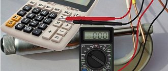
For your information. You can use a multimeter to check the calculated data. Measurements are performed in the appropriate range, taking into account the amplitude of the signal, alternating (direct) current.
Measuring cable resistance with a multimeter
When connecting an AC power source, the calculation algorithm becomes more complicated. For such initial conditions, use the formula:
ΔU = ((Pa * Ra + Pр * Ri) *L)/ U,
Where:
- Pa (Pр) – active (reactive) power;
- Ra (Ri) – relative active (inductive) resistance of the line in Ohms per kilometer.
For certain conductor materials, the initial data is taken from the reference book. By analogy with the mentioned standards, the voltage reduction should generally not be more than 5%. Additional restrictions are applied taking into account the characteristics of electrical networks and connected consumers (from 1% to 12%). The current rules are clarified according to the text of the latest edition of the PUE.
The above calculation results convincingly confirm the advantages of lower resistivity of copper wire. When using an aluminum analogue, the amount of material for transmitting electricity with standard losses increases significantly. For a comprehensive analysis, the best indicators of copper in terms of strength and flexibility should be taken into account.
Aluminum is less expensive and lightweight. But when working with this material, vibration effects and movements during operation should be excluded. Bends are designed with particular care to maintain the integrity of the conductor. Electrical contact is disrupted by the formation of oxides on the surface of products made from this metal.
For your information. In certain situations, free space for laying the route will mean a lot. In terms of space saving, copper has the advantageous parameters.
Selection of conductor cross-section based on permissible heating
As the current increases, the temperature of the conducting metal increases. At a certain level, the protective insulation layer made of polymers is damaged. This causes short circuits and flame formation. Dangerous situations are prevented by correct calculation of the cross-sectional area. The method of laying (joint/separate) has a certain significance.
Selection of cable products taking into account heating
Selection of cross section based on voltage loss
As shown in the calculations, with a long route length it is necessary to take into account the voltage reduction and the corresponding energy losses. In large projects, the entire current circuit with switchgear and connected loads is considered.
Selection based on acceptable losses
To accurately determine suitable cable products, the characteristics of the operating process are considered. They make the necessary reserves to prevent emergency situations when connecting new consumers and voltage surges in the power supply network.
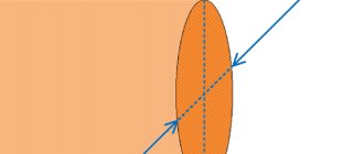
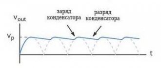
Voltage drop on the wire
The article will be specific, with theoretical calculations and formulas. For those who are not interested in what comes from and why, I advise you to go straight to Table 2 - Selecting the wire cross-section depending on the current and voltage drop.
And also - calculation of voltage losses on a long powerful three-phase cable line. An example of calculating a real line.
So, if we take the power constant, then as the voltage decreases, the current should increase, according to the formula:
P = I U. (1)
In this case, the voltage drop on the wire (losses in the wires) due to resistance is calculated based on Ohm’s law:
U = R I. (2)
From these two formulas it is clear that as the supply voltage decreases, the losses on the wire increase. Therefore, the lower the supply voltage, the larger the cross-section of the wire must be used to transmit the same power.
For direct current, where low voltage is used, you have to carefully approach the issue of cross-section and length, since these two parameters determine how many volts will be wasted.