Published on Sep 21, 2014 Category: Mechanics |
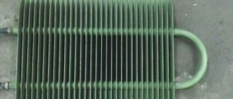
When designing and manufacturing bent parts from pipes and rods, the task of determining the length of the development - the length of a straight workpiece before the start of the bending process - always arises.
Continuing the topic...
...calculating the length of the development of parts bent from sheet metal of rectangular section, I present the calculation in Excel of the length of the development of parts made of rods and pipes of round cross-section.
The calculation program is written according to the classic strength of strength formula! Practical results will differ slightly from calculated values due to a number of factors, which were already mentioned in the article on sheet metal bending (link to this article in the previous paragraph). However, the program presented below will ensure accuracy when bending a pipe for the manufacture of a prototype.
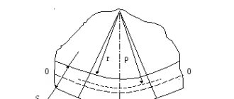
Below this text the figure shows the calculation diagram.
The radii of the neutral layers of each of the curved sections are calculated using the formula:
rni =((4* Ri 2 - D 2 )0.5+(4* Ri 2 - d 2 )0.5)/4
The neutral layer is the surface closer to which, closer to the center of the bending radius, the pipe material is compressed during bending, and further from the center of the bending radius, it is stretched.
The length of curved sections when bending a pipe is determined by the formula:
li=π*αi/180*rni
Here the angle αi must be in degrees.
The total length of the development is calculated by summing the lengths of straight and curved sections:
L = ∑( Li + li )
Program for calculating the length of development in Excel when bending pipes.
To perform calculations we use MS Excel. You can use the Calc spreadsheet processor from the free Apache OpenOffice or LibreOffice .
Initial data:
Let's assume that in the example under consideration, the part consists of three straight and two curved sections (as in the diagram above).
1. Write down the outer diameter of the pipe D in millimeters
to cell D4: 57,0
2. the value of the internal diameter of the pipe d in millimeters
to cell D5: 50,0
Attention!!! If the development length of a solid round bar is calculated, then d =0!
3. the length of the first straight section L1 in millimeters
to cell D6: 200,0
4. the axial bend radius of the first curved section R1 in millimeters
to cell D7: 300,0
5. the bending angle of the first curved section α1 in degrees
to cell D8: 90,0
6. the length of the second straight section of the part L2 in millimeters
to cell D9: 100,0
7. the axial bend radius of the second curved section R2 in millimeters
to cell D10: 200,0
8. the bending angle of the second curved section α2 in degrees
to cell D11: 135,0
9. the length of the third straight section of part L3 in millimeters
to cell D12: 300,0
10-15. Entering the initial data into Excel for our example is complete. We leave cells D13…D18 empty.
The program allows you to calculate the development of parts containing up to five straight sections and up to four curved ones. Bending a pipe with a large number of sections requires a slight modernization of the program to calculate the development.
Calculation results:
16. the length of the first curved section L1 in millimeters
in cell D20: =IF(D7=0;0;PI()*D8/180*((4*D7^2-$D$4^2)^0.5+(4*D7^2-$D$5 ^2)^0.5)/4) =469,4
17. the length of the second curved section L2 in millimeters
in cell D21: =IF(D10=0;0;PI()*D11/180*((4*D10^2-$D$4^2)^0.5+(4*D10^2-$D$5 ^2)^0.5)/4)=467,0
18-19.Since in the example under consideration there are no third and fourth curved sections, then
in cell D22: =IF(D13=0;0;PI()*D14/180*((4*D13^2-$D$4^2)^0.5+(4*D13^2-$D$5 ^2)^0.5)/4)=0,0
in cell D23: =IF(D16=0;0;PI()*D17/180*((4*D16^2-$D$4^2)^0.5+(4*D16^2-$D$5 ^2)^0.5)/4)=0,0
20. The total length of the part development L in millimeters is summed up
in cell D24: =D6+D9+D12+D15+D18+D20+D21+D22+D23=1536,3
The development length of the curved pipe was calculated using MS Excel.
CALCULATOR AND GENERATOR OF A CYLINDRICAL SHELL DRAWING
Using this calculator you can calculate the development (cutting) for rolling a cylindrical shell. When bending sheet material, the inner side is compressed and the outer side is stretched. There is a place on the sheet whose fibers do not compress or stretch. This place is called the "neutral line". It is along this neutral line that the calculation must be made. Metal shells are widely used in the manufacture of containers, pipelines, air ducts, drains, bunkers for bulk materials, etc.
When calculating, the following letter designations are used:
- R internal — inner radius of the shell;
- S—thickness of the shell wall (blank sheet);
- D is the outer diameter of the shell;
- h—shell height;
- β is the sweep angle;
- H - one of the sides of the scan;
- L is the second side of the scan.
K-factor is a coefficient indicating the displacement of the neutral layer during bending depending on R internal.
and S. When constructing a development in engineering graphics, the K-factor is not taken into account. The diameter for development calculations is assumed to be external. Form for calculating the dimensions of the reamer shell dimensions D
S
h
When calculating shells for elliptical bottoms according to GOST 6533-78, the base outer diameter should be taken into account: 133, 159, 168, 219, 273, 325, 377, 426, 480, 530, 630, 720, 820, 920, 1020, 1120, 1220, 1320, 1420. Or base internal diameter from: 250, 300, 350, 400, 450, 500, 550, 600, 650, 700, 800, 900, 1000, 1100, 1200, 1300, 1400, 1500, 16 00, 1700, 1750, 1800, 1900, 1950, 2000, 2200, 2400, 2500, 2600, 2800, 3000, 3200, 3400, 3600, 3800, 4000, 4500. The outer diameter is included in the calculations, so the inner diameter should be add 2 thicknesses walls (leaf).
development dimensions K-factor
L
H
H and L are important when planning material purchases. These parameters are indicated without allowances. DON'T FORGET TO POST THEM AT YOUR OWN DISCRETION!!!
It is possible that this drawing cannot be taken into production (it is not ideal), but it can be used at the cost calculation stage for approval with the customer.
Drawing generation form (dated 08/31/21)
To generate a drawing, it is necessary to make a calculation. If the values change, you must click on the drawing generation button again.
X and Y centering X cone Y cone
X sweep
Y sweep
To move the cone image, change the X and Y values of the cone.
To move the scan image, change the X and Y values of the scan. CONE SCALE :
To scale the cone image, change the scale cells in the desired direction.
SCAN SCALE :
To scale the scan image, change the scale cells in the desired direction.
code (max 28 characters) name (max 18 characters) sheet thickness steel grade
Development using the example of a truncated cone
The development of a cone can be obtained automatically using the Equipment: Developments application, or you can construct a cone using a sheet body and develop it. Let's consider both methods.
Construction of a development of a truncated cone made of a sheet body
- Let’s create a sketch on the XY plane (left-click on the XY plane and select the “Create sketch” command from the pop-up menu);
- Let's construct a circle of arbitrary diameter in the sketch with the center at the origin of coordinates
- Let's exit the sketch by clicking on the mode indicator and create a plane offset from the XY. Let’s choose any distance. The “Displaced Plane” command is located on the “Auxiliary Objects” toolbar (the location of the command is shown in the figure). After calling the command, you need to click on the XY plane and set the distance in the Options Bar, and then confirm the creation of the plane with the “Create Object” command.
- We create a sketch on the offset plane, in the sketch we construct a circle of arbitrary diameter with the center tied to the origin of coordinates (similar to points 1-2). Exit the sketch by left-clicking on the mode indicator. As a result, the part should look like this:
- We build a truncated cone with the “Ruled shell” command, which is located on the “Sheet body elements” panel in the “Sheet modeling” set. By running the command, we indicate Sketch1 and Sketch2, you can specify them in the tree, you can simply click on the circles in the model window. You also need to set the wall thickness of the truncated cone in the Options Bar. To confirm the creation of the body, click the “Create object” button
- The truncated cone has been created, now you need to unwrap it. To do this, use the “Expand” command from the Quick Access Toolbar. After calling the command, click on the conical face and click “Create object”. You can switch from a scan to a truncated cone by pressing the scan mode
- All that remains is to transfer this development from 3D to the drawing. To do this, create a new drawing document. We go along the path: Main text menu - Insert - View from model - View from model... Specify a part with a flat pattern (be sure to save the file with the part, otherwise it will not appear in the list). Check the “Sweep” checkbox on the Options Bar. As a result, a sweep view will be created.
Constructing a development of a truncated cone using the application
Application Equipment: Reamers allows you to build a development of parts having the form:
- truncated cylinder;
- straight circular cone;
- truncated right circular cone;
- a circular cone, truncated not parallel to the base;
- an inclined circular cone truncated parallel to the base;
- tees;
- transition from rectangular to round;
- pipes of rectangular and polygonal cross-section;
- bends
Construct developments of surfaces having a shape like:
- cylinder;
- cone;
- Torah;
- spheres.
Appendix Equipment: Reamers are included in the KOMPAS Mechanical Engineering configuration and are purchased separately from the basic KOMPAS. If the Mechanical Engineering Configuration is installed on your computer, you need to connect the Application. To do this, go to the following path: Main text menu - Applications - Configurator - expand the Equipment section in the list - select the line Equipment: Reams and click on the "Connect" link
Once connected, the Application will appear in a set of dashboards. You will need to select the Equipment: Developments panel and in the panel select the type of object whose development we want to obtain.
Let's construct a development of a truncated cone, just like in the first example. Select the command “Conical pipe type 1”. On the Parameters Panel, set the data for the truncated cone: 2 diameters and height and click “Create object”
A file recording window will open in which you need to specify the document name
We get a development drawing with dimensions:
Constructing a pipe development
Constructing a development of a pipe can be done by analogy with constructing a development of a truncated cone:
- by constructing a pipe with a sheet body;
- by constructing a development with the Application Equipment: Developments
If we use the first method, then we built the truncated cone using the “Ruled shell” command, and the pipe needs to be built with the “Shell” command
Otherwise everything is very similar. A sketch is also created on any of the system planes, such as XY. A circle is being built. The “Shell” command is launched, the pipe length and wall thickness are indicated. The development drawing is again obtained by analogy with the step-by-step description of obtaining the development of a truncated cone.
If you use the method with the Application Equipment: Reamers, but there you will need the command “Cylindrical pipe type 3”. The pipe parameters are indicated and a scan is obtained automatically.