05.06.2020
The machine allows you to process parts for a wide variety of purposes. Modern universal models have many parameters, with the help of which work with products is carried out without difficulties. But this tool also has a vulnerable aspect - interaction with objects of inappropriate shape. A lathe chuck faceplate is an easy solution in situations like this.
Large products do not fit into the machine itself, so it is impossible to secure them in the required position. As for non-standard shapes, usually the clamping device, which acts as a fastening element, damages them. Squeezing is not very good for flat materials, the edges may crack or bend. It is especially unpleasant when various fittings are located in these places. And the object itself is quite capable of being damaged in such a situation. Accordingly, it is strictly not recommended to start processing without a specialized adapter.
Why do you need a faceplate on a lathe: purpose
When you have to work with metal products, the first thing you need to do is securely secure the workpiece so as not to damage the surface and also not to injure yourself. Each equipment has its own locking devices, but they have significant limitations on their use. Turners using standard equipment can only process certain blanks that have a small diameter and a regular shape. But if for some reason it cannot be placed in the cartridge, then fastening is done using a special washer. This is usually required when the workpiece:
Jig boring machines
The main feature of jig boring machines (Fig. 3) is the high precision of processing parts.
Figure 3. Jig boring machine.
Increased processing accuracy is achieved through the use of various high-precision mechanisms for calculating the coordinates along which the cutter moves. There are several main methods for calculating coordinates implemented on jig boring machines:
The spindle on the machines of this subgroup is located vertically. But sometimes there are models with a horizontal spindle. The spindle head, in addition to changing the speed and direction of rotation, also carries out a working feed, increasing or decreasing the depth of penetration of the cutter into the part.
The table has two degrees of freedom. A part fixed on a table can move in the longitudinal and transverse directions. Moreover, the magnitude of these movements is controlled with high accuracy by the coordinate system.
Also, on jig boring machines, in addition to performing the entire range of operations characteristic of boring group machines, marking operations are performed.
Operating rules
Let's briefly go through the main nuances of how to install and work with such an element, depending on the equipment.
On universal
In principle, what is a faceplate for a metal lathe chuck? It is an adapter with a special type of clamps. But at the same time, he himself is placed on the base according to different laws.
- An uneven surface, asymmetrical, always implies mounting on a clamp.
- To straighten the axle, you need to use lifting bars.
- Use a counterweight (usually included) to avoid vibration.
On rotary turning machines
There are fundamental differences here. If we constantly mentioned above that the washer is simply an additional adapter designed to simplify work with unusual workpieces, in this case it is the main element of the fastener. After all, the machine itself is a round table, on top of which a disk with several bushings is placed. Objects are mounted on them. What’s interesting is that even if the bushings themselves break or become unusable, they are replaced separately. And it becomes a kind of working surface that cannot be changed.
Design
It makes no difference which machine is used: metal or wood. This device for securing objects is suitable in both situations. The most common discs are made of steel and cast iron. Grooves and recesses are made on them. The main goal is reliable fixation of the object. Depending on which grooves are located on the surface, there is a certain list of shapes with which a given fastener is allowed to interact.
In addition, the equipment itself is often connected to the spindle using hubs. But the models that are mounted on the cartridge are easy to distinguish. The hubs do not look like cones, they are strict cylinders.
In many variations, the size of the faceplate allows you to install additional clamps on it. Usually clamp type. Then the future product is clamped according to the principle of a vice if it has protruding parts that ignore the mechanical compression pressure.
Do not forget that atypical processing is always a certain risk. The manufacturer did not intend such an action, which means there is a possibility of destruction of the product upon startup. And also the scattering of fragments over a large area. Accordingly, the main weapon in this case is a thorough balance check, calculation, and test run. Theoretically, a danger also arises for the equipment; it can be damaged if the fasteners are set inaccurately.
Attention and caution are the main rules that must be followed.
Types and purpose of washers
This is not a universal device. Hence the large number of varieties, each of which is used for fastening packages of different shapes. In some cases, several types are used at once.
T-slot disc
From the name it becomes clear that the device has grooves cut out in the shape of the letter “T”. Exactly the same ones are present on the tables of milling machines. On different devices, the grooves are located at different frequencies, hence the variety in their number.
It is into these grooves that the fastening nuts are inserted so that they do not interfere with the contact of the workpiece and the faceplate. At the bolted location, special stops can be used. They are also located in grooves.
Read also: Accused of something you didn’t do
With through grooves
There are also grooves here. But they are cross-cutting. Therefore, the part is fastened with threaded clamps. Often the workpiece is simply screwed onto the back of the disk with screws or bolts.
Two types of groove configurations are used:
- radial;
- around the circumference.
Other turning devices can be installed in such a faceplate.
With holes
In the design of this type, through holes are made in accordance with the dimensions of the workpiece. There is also a large hole in the middle of the disk. It has a thread with which the washer is attached to the shaft.
As for fastening the workpiece, it is connected to the fixture using screws or threaded clamps. If wood is provided for processing, then ordinary screws are used as fasteners.
Leashes
This type of faceplate for a lathe is used to transmit rotation to workpieces that have an internal cavity. It is into this that the hub, which is part of the washer, is inserted.
To fasten the device and the workpiece, an additional element is used - a clamp. It connects two positions, transmitting rotation.
There is another variety in which, instead of a hub, slots are made around the circle on the plane of the disk. The package to be processed is inserted into them.
With a square
This version of the device is used if it is necessary to process parts with low rigidity. To do this, the workpiece is placed on a special base, which is a square. The latter is attached to the faceplate on one side, and to the package on the other. That is, it performs the functions of an intermediate device.
Attention! The square must be attached to the washer at several points. The larger the contact area, the more reliable the connection.
Types of faceplates
Today, there are several classifications that divide existing faceplates into groups according to different criteria. So, among the common faceplates on the market, the following types are distinguished:
- Smooth;
- With regular threaded holes;
- With radial or classic, circular, threaded holes (grooves);
- Faceplates with a leash.
Since each type has its own characteristics, it makes sense to dwell in a little more detail on each type.
According to the regulatory document GOST 4082-69, special requirements are imposed on faceplates made of steel, for example, their tensile strength must be at least 4.9 MPa.
This approach to manufacturing materials is easily explained:
- Cast iron is little susceptible to thermal changes;
- This material is easy to process;
- The cost of cast iron is very low compared to other materials of similar quality.
Smooth faceplates
The most common type of faceplate is smooth; in the vast majority of cases it is used when it is necessary to process a part in the form of a regular or stepped ring . Thus, the faceplate, already installed in the structure of the lathe, is necessarily centered using a surrounding element located on the flange.
The workpiece being processed is secured using special clamps or through a central clamp , which ensures reliable installation of the part and its immobility. Clamps are usually used with the simplest possible design in order to eliminate any risks, because they consist of a screw, two washers and a nut, which, when connected, provide an excellent level of fastening.
If fastening must be done using squares or special racks , and only a smooth faceplate is available, then the fastening procedure is slightly different: after centering the faceplate, the square is installed directly on it .
It should be noted that centering should be carried out as responsibly as possible, since otherwise the imbalance will negatively affect the service life of the spindle.
Faceplates with threaded holes
The fundamental difference between such faceplates and the previous type is the presence in the hole, which is located in the middle of the faceplate, and a thread, which is intended for mounting it on the shaft of a lathe . Accordingly, in this case, the faceplate acts as a kind of substitute for the flange, since fastening to the upper end of the spindle is carried out directly without any intermediaries.
Moreover, such faceplates are often equipped with several holes (usually three), into which clamps (which are sometimes called “cams”) are screwed, necessary for additional fastening of smaller workpieces.
Sometimes faceplates can be put on threaded bushings made independently by employees of certain enterprises. Such bushings can either be welded onto the shaft or soldered. Similar parts are produced to increase the reliability of fasteners, but the vast majority of experts agree that faceplates with existing threads are more reliable.
Faceplates with radial and circular grooves
The faceplate with radial grooves is radically different from those listed above:
- firstly, threaded through grooves are connected into groups , which are separated from each other by special grooves,
- secondly, the faceplate can be either threaded or without .
The number of threaded grooves can vary, and there are also faceplates in which their number varies sharply (for example, three in one group and six in another). The grooves can also be located in the grooves themselves, but it is not at all necessary that all of them be through, some can only reach half of the part.
The main purpose of radial grooves is to fix a non-standard-shaped workpiece using screws during processing. Stiffening ribs can be additionally screwed onto the rear side.
Stiffening ribs are installed to increase the potential impact on the part: since classic, factory faceplates are devoid of them, representing a solid piece of metal or alloy, their strength and “durability” is achieved by increasing weight.
There is even a special requirement for cast iron faceplates - their thickness must be at least 5 mm).
Drive faceplates
Drive faceplates (which are sometimes called gear plates) differ from those described above in design: for example, in the body of the part there is a straight T-shaped profile cut where the drive is located (in it, by the way, there is another T-shaped groove, which is parallel to the first and where the clamps).
The clamping elements, which can be adjusted with the appropriate screws, also have T-shaped grooves, where the cams are already located, providing direct fastening (they are able to move freely along the groove, therefore they are already installed on the surface of the workpiece).
The principle of operation is quite simple: the workpiece is installed in the center, after which the clamping elements moved towards it from several sides and the cams are additionally placed on its surface , their task is to additionally cover the workpiece.
additional reliability in use is ensured by the presence of T-shaped grooves located in the clamping elements. This makes it possible to process even multi-stage workpieces.
Improvement of technical parameters
Tuning to increase power
The design of the motorcycle engine allows for tuning to increase its power. One option is to re-press the engine crankshaft and change the support bearings. Usually, secondary shaft bearings from a Java motorcycle were installed as new bearings. This restoration made it possible to achieve an increase in engine power of the IZH Planet - 5 by 10-15%.
The next option for adding power was to increase the cylinder volume. For this purpose, its upper part was cut off and the sleeve was bored to 76 mm. Then the appropriate piston was installed, usually a piston from a Planet Sport motorcycle was used.
Increasing motorcycle speed
After this operation, the speed of the motorcycle increased, according to some sources, to 160 km per hour. Therefore, work to increase engine capacity was carried out by owners who planned to operate their vehicle mainly on highways.
The most difficult technical tuning option for adding power to the IZH Planet - 5 is the installation of supercharging. For this purpose, an exhaust valve is installed, the device of which corresponds to the analogues on the sports versions.
Then an exhaust resonator is installed, which has sharply directed parameters. Its task is to create a wave backpressure of the fuel mixture. Next, a spool valve is installed to obtain asymmetrical phases of engine operation, which avoids the direct release of the spent mixture.
Performing supercharging on the engine of the Fifth Planet is a rather complex process and therefore is not widely used.
Improved grip
As engine power increases, it is necessary to carry out work to improve the clutch. Under standard conditions, the standard clutch works reliably.
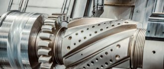
Boring machines
One of the most common groups of equipment in the metalworking industry is boring machines. This group of machines is widely used both in individual and large-scale production. A distinctive feature that makes boring machines stand out as a separate group is the ability to perform metal-cutting operations in hard-to-reach places on the workpieces.
The following metal-cutting operations are performed on boring machines:
Classification of boring machines is carried out according to several criteria. Let's look at the main ones.
1. Main feed direction:
2. Control method:
3. Maximum linear dimensions of the workpiece.
4. Power of drive motors.
5. Processing precision.
Let's look at the main subtypes of boring machines.
Varieties
Due to the widespread use of faceplates, it has a large number of modifications, mounting options, etc., therefore, a large number of types.
Universal and special
Typically, such faceplates are a mixture of several of the above types. Such faceplates are created for working with more complex parts, but even they are not always suitable for them, which is why it is modified to the required parameters.
Part with squares
When processing products with low rigidity, modifications with squares are used. The workpiece in such devices is mounted on a separate flat or prismatic base.
The base is made in the form of an angle, its second edge is attached to the surface of the washer. To ensure the integrity of the workpiece, fastening is provided at several points over a large area.
Leashes
Such faceplates have two T-shaped holes, in one of which there is a leash, and in the other there are clamps. The part is attached to the surface with screws in the center. In addition, T-shaped grooves are responsible for fastening.
With holes
This faceplate has a special design in the center for threaded connection to the spindle. The part has 3 holes for clamps.
Sometimes washers are attached to homemade bushings by welding. This is done for a more durable fixation; however, models with an already modified design are sold.
T-slots
On the surface of such equipment, T-shaped grooves are made, similar to those used on tables of milling machines. Special stops or fastening nuts are inserted into the grooves. During processing, the product is pressed to the plane with screws.
The design of the device makes it possible to fasten almost any product. The grooves on the surface of the disk are usually located orthogonally. Depending on the purpose, the number and frequency of grooves change.
With through grooves
Basically, these faceplates are needed for fastening irregularly shaped parts. There are several holes on it, some of them are through, and some are not.
This type does not have a certain number of recesses. Some of them are in grooves. The disk also has stiffening ribs that are mounted.
What kind of node is this, what is it for?
A lathe chuck is a device designed for mounting a workpiece on lathes, special, and universal machines. The chuck itself is rigidly connected to the spindle and transmits torque to the parts.
To produce surfaces of the correct round shape, the part must be aligned exactly in the axis of rotation of the spindle and have no runout. It is most convenient to mount round workpieces, hexagons, into a self-centering chuck. The best option for such a chuck is a three-jaw chuck. Compressed from three sides, the workpiece itself takes the desired position.
In mass and small-scale production for the manufacture of small and medium-sized parts such as shafts, a chuck with a body diameter of 160 mm is used. The Archimedes spiral installed inside converts the weak muscular force when turning the gear with a key into a strong force that presses the cams to the part. As a result, the workpiece is manually firmly secured in the chuck and can withstand the stress of processing.
Important!
The three-jaw chuck allows for quick installation and removal of parts, increasing worker and equipment productivity.
Fastening the part to the faceplate
The part is fastened to the faceplate using various auxiliary elements, which are designed to additionally hold the part. If it is possible to install the part symmetrically, use a “corner”, which is placed in the middle of the faceplate, and the workpiece is already attached to it. It should be remembered that the more symmetrical and balanced the part is located on the faceplate, the better its processing will be performed . An example of such an installation is shown in the figure below.
As you can see, just above the spindle with the tip there is a round part - a counterweight , which is necessary when working with:
- Weighty workpieces;
- Workpieces center of gravity is greatly shifted relative to the central axis;
- Severely irregularly shaped workpieces.
installation of the counterweight is carried out for each specific part; its mass and position on the faceplate are first calculated.[/warnin]
Asymmetrical parts are attached to the faceplate in several stages:
- Firstly, it is necessary to install racks that will “hold” the part from several sides at the same time. The racks must be parallel to the axis of the faceplate, otherwise the workpiece may fall out.
- Secondly, the clamping elements are placed as close to the workpiece as possible . Finally, the correct installation is ensured using a surface planer.
Installation and use rules
There are three most common mounting options. They depend on what equipment is used for fixation.
For universal lathes
For fastening, strips and bolts (pressed or screwed into the chuck jaws) are used. Parts that are symmetrical to the axis are secured using a central element or clamps. But asymmetrical elements have to be handled a little more difficult. To do this, use various linings and stands, with the help of which you can achieve an increase in level. The clamping bars must be pulled as tightly as possible to the part itself, and their location must be strictly parallel so that they do not jump out during rotation. To ensure correct installation, use a thickness planer. When using, it should be taken into account that the workpieces being processed very often have a displaced center of gravity due to their asymmetrical, non-cylindrical shape. Therefore, before turning on the machine, you need to install counterweights, which, by their mass and location, will completely compensate for the difference in weight of the blank. If this is not done, the following will happen:
- Spindle runout will increase.
- The vibrations will increase.
- The service life of the equipment will be reduced.
- The precision of metalworking will be significantly affected.
To balance the product, it is enough to manually turn it. If you can’t move it with your hands, then the counterweights are doing an excellent job.
How to make a homemade mini wood lathe with your own hands
A simple homemade lathe can be made from scrap lumber and a few old parts. Making a woodworking machine will not be difficult, and you need the most common tools; these can be found in any household. And how many pleasant little things will come out of the incisor!
Small machine for home
almost finished machine and faceplate We present a mini-lathe with dimensions of 800 x 400 x 350 mm. On it, they process parts with their own hands up to 25 cm in diameter and up to 40 cm in length.
Design elements:
- electric motor from the pump;
- front pillar - high-power electric sharpener for a couple of stones;
- caliper with support and adjustment;
- the frame is welded from a metal profile;
- the rear pillar is an element of a drill.
You will need plumbing equipment:
- electric drill;
- angle grinder;
- file;
- welding machine.
It is necessary to purchase additional materials:
- metal corner and channel;
- piece of block, plywood 10 mm;
- two pipes with such diameters that they are placed coaxially;
- metal strips 20 and 40 mm;
- fasteners;
- drive belt (from the car).
Assembling a homemade lathe:
- Choose a sharpener with your own hands so that you can use it without modifications. The axle must be placed high, with sealed bearings and washers to secure the discs. We install disks for adjusting the speed of movement on one of the axis outputs, and a faceplate for the workpiece on the second.
- The bed consists of two parallel channels, between which there is a gap - a guide. The length of the guide is equal to the length of the workpieces. At one end we weld a channel in the shape of a P, on which the headstock will be installed. The second end can be closed with a corner.
- The machine support is a stand of two pipes inserted into one another to adjust the height. At the desired height, the structure is fixed with a bolt. A horizontal bar is welded as a stop. Weld the stand with your own hands to the base using two corners secured to the guide using a pressure plate and a bolt with a nut. To correctly select the rotation speed of the part, use the drawing. It is most convenient to take a pair of intersecting values. For smaller jobs on particularly hard wood, you can remove the belt and use just the sharpener motor. That is, it is possible to work with several rotation speeds.
- The drive pulley is made from an old drill chuck. The driven pulleys are cut out of thick plywood, glued in two layers. We also make the faceplate from plywood; we pre-cut holes in it for the self-tapping screws that will hold the part. The faceplate is screwed onto the front pillar axle with the part already attached.
- We install the metal base on two supports. On the side of the headstock we make a platform of thick plywood on which the electric motor will be placed. To be able to change the belt tension, the motor is attached to a small plate, which can be moved around the site and secured in the right place.
caliper and tailstock relationship between rotation speed, part diameter and material hardness
Simple tabletop mini machine
very simple, but gets the job done. The second homemade mini-structure consists almost entirely of wood, so the following is used in its manufacture:
- screwdriver;
- hacksaw;
- sandpaper;
- jigsaw;
- pliers.
And materials:
- board No. 5 is better than oak;
- two dies for parquet;
- screws No. 45, about 10 pieces;
- construction dowel;
- aluminum plate;
- electric motor (can be from an old VCR);
- shaft from an old cassette player;
- thick bicycle spoke or pin;
- bolt and nut.
Assembling a lathe with your own hands.
- We saw off a piece of board 30 x 15 cm to create a base.
- We cut out two sections lengthwise from the parquet blocks: one with an outer groove, the second with an inner one. We drill one hole for self-tapping screws 5 cm from the ends. The length of the die will be equal to the future workpiece.
- We screw the parquet slats to the base with the grooves inward, and we get guides. There should be a whole parquet floor between them.
- We will make the tailstock from parquet, about 10 cm high, choosing a notch in the middle. In the lower part we cut out a wide hole into which we glue the nut. Subsequently, a bolt will be screwed into the nut to secure the rear strut.
- We attach a block to the tailstock, onto which we fix the dowel using a metal plate.
- The support for the cutter will be made from a knitting needle bent into the shape of a long bracket located along the bed. We fasten it with a couple of screws.
- The headstock is a block of wood onto which an electric motor is screwed using a metal bracket. When fastening, use thin rubber gaskets that reduce vibration. Before final fixation, you need to align the front and rear centers.
- You can make a faceplate with your own hands from a plastic washer, which we glue onto the shaft with hot-melt adhesive. We fuse several sharpened pins into the faceplate to secure the workpiece.
The mini-machine is ready to use. The electric motor needs to be taken at 12 W and connected through the computer power supply, then the power is enough to process small wooden parts.
Thus, making a simple lathe with your own hands will not be difficult. Video about a homemade machine with a 125 W washing machine motor:
Horizontal boring machines
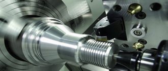
The main distinctive feature of a horizontal boring machine (Fig. 1) is the horizontal arrangement of the spindle. This type of machine is somewhat reminiscent of a conventional screw-cutting lathe. But there are several key differences in a horizontal boring machine. Firstly, the tailstock is missing. Instead of the tailstock, a movable rest is installed. Secondly, the faceplate with which the spindle is equipped has the ability to shift the cutter relative to the axis of rotation, which is not typical for a lathe. Thirdly, there is a table on which the part can be fixed.
Figure 1. Horizontal boring machine
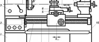
Let's look at the main components and elements that make up a standard horizontal boring machine.
Figure 2. Boring machine faceplate.
Today, horizontal boring machines that are equipped with a numerical control module are becoming increasingly common.
Can I do it myself?
With basic equipment and some lathe and engineer skills, home fabrication is possible. But the question remains about the necessity of such actions. After all, only the simplest variations can be made at home, and they are not difficult to find on sale, and they are cheap. But the economic feasibility of homemade equipment remains unproven.
Sometimes you need complex designs that cannot be found in stores. But usually their design is very complex, and manufacturing will take a lot of time.
However, if you decide to make it yourself, we will give some recommendations and show you how to do it.
Blank
We take a flat beam. On its surface we mark the necessary parameters with a pencil. For accuracy we use a compass. We take into account that you need to take 1-2 mm of margin. After all, there will be a gluing stage, which often steals a couple of millimeters. We use hot glue. When we coat the material, it is necessary to retreat 1 cm from the edge, otherwise the excess will flow out. You should hold the elements to be glued under pressure for some time.
Now we take the body washer and weld half of the nut, which stands on its edge, to its center. After cooling, the element can be placed on the spindle. You can drill several holes on the surface for mounting tools.
Be sure to paint the steel to prevent it from rusting. The manufacturing process is presented in more detail in the video:
In the article we talked about faceplates for a lathe chuck. Choose your equipment carefully to achieve the best results.
Criterias of choice
Before buying a device, you need to understand exactly what it is needed for and where it will be installed.
Important selection criteria:
- Measuring range. Rule: the working pressure in the pipeline should be no more than 2/3 of the maximum of the measurement scale, but not less than 1/3. If the pressure in the pipe is 5 atm, then you need to buy a pressure gauge with a scale of 0...10 atm.
- The accuracy class varies from 0.15 to 3. The lower, the more accurate. For a cold or hot water supply system, an accuracy of 1.5% is sufficient.
- The location of the fitting can be radial or end when it is from below; and axial or frontal, when he is behind.
- Operating temperature range.
- Temperature operating conditions.
- Working medium (water, steam, oil and so on);
- Diameter. It should be such that the device fits in the chosen location and the dial is clearly visible.
It is also necessary to pay attention to the connecting thread of the fitting. It can be metric - its parameters are measured in mm, denoted by the letter M, for example M20/1.5, which means the outer diameter is 19.9 mm, the inner diameter is 18.7 mm, pitch 1.5. Domestic manufacturers use it by default
Domestic manufacturers use it by default.
Pipe thread is designated by the letter G. G1/2" means an outer diameter of 20.9 mm, an inner diameter of 18.6, a pitch of 1.8 mm or 14 threads per inch.
The technical passport of a new device must contain a factory verification mark. A verification period of less than a year confirms that the device gives correct readings.
Diamond boring machines
Diamond boring machines (Fig. 4) are designed for final (fine) processing of parts.
Figure 4. Diamond boring machine.
The diamond boring machine consists of the following main components.
In addition to good processing accuracy, the diamond cutter provides a high class of surface finish. These machines are used where high purity and precision of processing are required, for example, in automobile and aircraft engines, machine tool parts, and control and measuring equipment.
Source