Not many enterprises provide services for the production of various metal products to order according to customer drawings. If you need to perform turning work in Novosibirsk, it is best to contact the SibPromDetal company, where you will be offered not only mechanical methods for manufacturing parts from steel, but also cast iron.
The technology for producing products of complex shapes from metals by turning is quite complex. With computer-controlled machines, the task is simplified, but the equipment is quite expensive and requires specialized knowledge when setting up and operating.
Screw-cutting lathes are more affordable and can be purchased, if necessary, even for a home workshop. Therefore, in the future we will talk about them, namely, how to turn a ball on a lathe.
Among the most accessible for home craftsmen, there are two main methods of turning an ideal spherical surface - using a copier and using various devices. Let's consider each of the options in more detail.
Is it possible to do this?
Creating a spherical part on turning equipment is a simpler process than it seems at first glance. In this case, you can use both auxiliary equipment, if the production of a small batch is planned, and standard equipment of the machine in the case of piece production. The most affordable way is turning using a previously prepared template.
For metal
Working with metal is an order of magnitude more difficult compared to other materials due to its higher hardness, but it is more familiar and does not have unusual features. Turning a ball will take at least two passes and will require working at high speeds to obtain a satisfactory result. In general, the process is little different from other turning operations and has no specific specifics.
On wood
Compared to a metal workpiece, a wooden workpiece is more amenable to processing, which is why it is possible to carry out processing not only with a lathe cutter, but also with hand chisels and crowns intended for this operation.
When turning, instead of the usual shavings, wood dust remains, so you need to work strictly in a respirator, turning on the hood. It would be a good idea to remove oil spills on the machine in advance and install a vacuum cleaner on the tool holder, which will simplify cleaning after work.
Which cutting tool to use
The production of parts on such machines is carried out using special turning tools. They must provide the following:
Turning cutters are classified according to different parameters. Depending on the type of work performed, they can be cutting, passing, shaped, scoring, etc. Cutters are made from various materials - diamonds, tungsten, titanium-tungsten and others. Depending on the design, these tools can be one-piece, prefabricated or combined.
The choice of a specific type of tool is carried out taking into account the modes of the work operations being carried out, the hardness of the workpiece, the geometric parameters of the cutting part and other characteristics.
Related video: Metal turning
Source
Alternative methods for making a topiary base
Polyurethane foam
We squeeze the polyethylene foam into a plastic bag to get a blank - a figure close to the shape of a sphere, but definitely larger than the required diameter of the ball. We wait until the sealant has completely hardened, remove the bag, and use a utility knife to give the mass the desired shape - not just a ball.
DIY foam ball
Instead of polyurethane foam, you can use a foam blank, for example, packaging from household appliances, or glue several sheets together to obtain the required thickness.
But the foam is non-uniform and crumbles a lot: making a topiary ball of the correct shape is difficult, and a lot of debris remains. You can also cut a base for a flat topiary from a foam sheet.
Papier-mâché technique
We inflate the balloon to the desired size, coat the surface with PVA, glue sheets of paper (you can use toilet paper), fragments of old newspapers or napkins. We continue to increase the mass, generously coating each layer with glue, gaining a thickness of at least 7-10 mm.
After the workpiece has completely dried, carefully deflate and pull out the balloon; the frame remains. The result was a fragile but original ball for topiary using the papier-mâché technique. The method is labor-intensive, the base takes a long time to dry.
Knitting thread
The method exactly imitates the papier-mâché technique, but instead of paper, knitting threads are used: the result is a frame suitable for a light crown. We do not recommend using twine instead of yarn: the material is expensive and strongly absorbs glue.
Copier turning
To obtain the simplest copying device, you will not need much at all - a spherical template of a suitable diameter and two identical cutters installed in a cutter holder on one side with the same offset. Particular attention should be paid to the correct setting of the copying device - set the cutting tool at the same distance.
It is very convenient to do this using any part that has a cylindrical shape - a sample of a pipe or a steel rod. To set up, it is enough to secure one of the cutters with bolts, and install the second without fastening. Smoothly move the tool holder with the cross-feed handle, wait until both cutting edges touch the mandrel and fix the loose tool.
As a mandrel, you can use a ball on a rod pre-machined on a CNC machine or a ball from a bearing of a suitable diameter. To make it easier to secure the latter, it is necessary to weld a round rod of suitable diameter strictly in the center.
Turning technology is not particularly difficult. Initially, using a working cutter, usually a cutting cutter with a rounded cutting edge, rough grinding is performed. In this case, the copier (second cutter) moves touching the spherical template fixed in the tailstock quill through an adapter.
After preliminary giving the workpiece a shape close to the desired one, finishing turning is performed with a small thickness of the cut layer and feed. Final processing, if necessary, can be done with fine-grain sandpaper. The technology is demonstrated in more detail in the video below:
Ready-made balls for the tree of happiness
Purchased blanks and improvised bases for topiary:
- Styrofoam ball. For the tree of happiness, it is advisable to use ready-made foam balls with a diameter of 7 to 30 cm.
- Hanging rattan. Ready-made rattan balls are available at decor stores. In addition, you can make them yourself (rattan is wrapped around a balloon).
- Rubber ball. Limited selection of trunks for topiary: only a cable is suitable, which must be attached to the outside of the ball.
- A ball of knitting thread.
- Chipboard is a die-cut made of thick cardboard. Blank for flat topiary on a magnet, thickness 1-3 mm.
- Tennis ball. For miniature trees.
- Ostrich egg. An original base for Easter topiary. Ostrich eggs are very durable and decor sticks well to the surface.
- Foam ball. Multi-colored products are used by magicians to perform tricks, but are also great for our purposes!
- Wooden ball. They are rarely used, but for a certain design a wooden base is optimal.
Designation of taper in the drawing
When creating technical documentation, all established standards must be taken into account, otherwise it cannot be used in the future
When considering the taper designation in the drawings, attention should be paid to the following points:
- The diameter of the large base is displayed. The figure under consideration is formed by a body of rotation, which is characterized by a diametrical indicator. In the case of a cone, there may be several of them, and the change in the indicator occurs smoothly, not stepwise. As a rule, such a figure has a larger diameter, as well as an intermediate one if there is a step.
- The diameter of the smaller base is applied. The smaller base is responsible for forming the required angle.
- The length of the cone is calculated. The distance between the smaller and larger bases is an indicator of length.
- Based on the constructed image, the angle is determined. As a rule, appropriate calculations are carried out for this. In the case of determining the size from a printed image, using a special measuring device, the accuracy is significantly reduced. The second method is used when creating a drawing for the production of non-critical parts.
The simplest designation of taper also provides for displaying additional dimensions, for example, reference. In some cases, a taper sign is used, which makes it immediately clear about the difference in diameters.
There are quite a large number of different standards that relate to the designation of taper. The features include the following:
- The angle can be specified in degrees as a fraction or as a percentage. The choice is made depending on the area of application of the drawing. An example is that in the mechanical engineering field the value of a degree is indicated.
- In the mechanical engineering field, the concept of normal taper is included in a special group. It varies within a certain range and can be 30, 45, 60, 75, 90, 120°. Similar indicators are characteristic of most products that are used in the assembly of various mechanisms. At the same time, it is much easier to maintain such values when using turning equipment. However, if necessary, inaccurate angles can be maintained, it all depends on the specific case.
- When drawing the main dimensions, a drawing font is used. It is characterized by quite a large number of features that must be taken into account. Tabular information is used for correct display.
- To begin with, the taper icon is indicated from which the arrow is drawn and the value is displayed. The display features largely depend on what kind of drawing. In some cases, a large number of different sizes are applied, making taper application much more difficult. That is why it is possible to use several different methods for displaying such information.
In the drawing, the indicator in question is indicated in the form of a triangle. This requires a digital value that can be calculated using various formulas.
Read also: Not an integral part of a metal plane
How to turn a cone on a lathe: diagrams, methods
How to turn a cone on a lathe
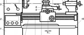
Lathes are used to turn workpieces during turning by using special cutters. If you have some experience, you can turn not only parts of a regular shape, but also, for example, a conical surface. To create a cone, you must have certain skills on a lathe.
Rotating the upper caliper slide
You can carry out the cone turning process using the following recommendation:
- We take the workpiece and secure it in the spindle, as well as the tailstock. Considering that the cone is manufactured with high precision, the diametrical size and angle may have slight deviations. If the workpiece is made of hard material, carbide cutters should be selected.
- Processing can only be carried out in compliance with safety precautions through the use of personal protective equipment.
- Selecting the cutting speed on the lathe. Machining of conical surfaces can be carried out at a speed that is selected depending on the durability of the cutting edge and the hardness of the material. If there is no exact data that allows you to calculate the cutting speed, you should follow the test path - from lower to higher values.
- The installed workpiece must be given a cylindrical shape. For this, a through cutter is used, first roughing is carried out to remove a large amount of unnecessary metal. Processing near the cams is carried out with a bent cutter.
- The production of precision parts occurs in two passes: roughing and finishing. On a lathe, finishing turning is carried out with a special cutting tool at a certain speed and feed.
- To create small conical surfaces, the top of the caliper is rotated at a certain angle, which should be equal to half the angle of the cone at the apex.
In a similar way, you can create conical surfaces without using a special device.
Method of displacement relative to the axis of centers
Shifting the centers also makes it possible to obtain a Morse taper on a lathe. However, in this case, turning can only be done on external conical surfaces. The advantages of the method under consideration include:
- It is possible to make a long Morse taper.
- A mechanical support feed is used, which makes it possible to use conventional models of lathes.
Center axis offset
Significant disadvantages include:
- Low precision with which the part can be made.
- In the process of obtaining a cone, the center holes become skewed.
The amount of displacement of the tailstock during the creation of conical surfaces is determined using a right triangle.
Cone ruler
Some lathes are equipped with special tapered rulers. Such a device allows you to process external and internal surfaces when the angle of inclination does not exceed 12 degrees. In this case, a cone shape can be made by combining longitudinal and transverse transmission.
When using a ruler, you can select the angle that will be created by simultaneously moving the caliper in the longitudinal and transverse directions. A special ruler allows you to maintain the correct angle throughout.
Using a wide angle cutter
A fairly simple way to obtain a tapered surface on a lathe is to use a corner cutter. With its help, you can create a cone of short length; the cutting edge should be straight. The angle of the taper can be adjusted by sharpening the edge or setting it at a specific angle to the workpiece.
Turning a cone with a cutter
All of the above methods require certain skills in operating a lathe. In some cases, for large-scale production, special copiers are made. For small-scale production, a method that uses a ruler or turning the lathe slide or shifting the headstock is suitable.
Features of determining cutting modes during turning
First of all, you need to select the processing depth, then the feed and speed. It is important to follow exactly this sequence - in order of increasing degree of impact on the instrument. First, those characteristics are calculated that can only minimally change the wear of the cutter, and finally those that affect the service life to the maximum.
Parameters should be determined for the maximum capabilities of the equipment, necessarily taking into account the dimensions, metal, and design of the tool.
An important point is to find a suitable roughness. Plus, it’s best to choose a blade for a specific material, because cast iron has one strength and hardness, while aluminum has a completely different one. Do not forget also that during the process the part heats up and the risk of its deformation increases.
The choice of cutting mode when turning on a lathe continues by establishing the type of processing. What will it be, rough or fine? The first is rough; tools made of hard steel and capable of withstanding the high intensity of the technical process are suitable for it. The second is thin, carried out at low speeds, with the removal of a minimal layer of metal.
The depth is determined by the number of passes during which the allowance is removed. Feed is the distance covered by the edge during rotation of the workpiece, and can be one of three types:
The speed largely depends on what kind of operation is being performed, for example, when facing it should be high.
Turner services
Finding someone who will provide turner services in Moscow is not very easy. There are fewer and fewer good turning specialists left, as young people do not go to study for blue-collar jobs. Turning works photo. We are proud that we have excellent turners in our team. Before answering your question about the cost of turning services, we need to know from you:
- drawing or drawing with exact dimensions (or sample part) (can be sent by email
- type of material processed and type of work required
- required quantity
- material for work, yours or ours
- other recommendations and wishes.
We try to fulfill all orders on time and with high quality. Our prices are quite affordable. Turning works in Moscow.
metal turning works master turning works price
TURNING SERVICES. Turning work photo
Despite the presence of many methods of forming processes (casting, powder metallurgy, etc.), cold metal working is widespread in the engineering industry.
Very often it is simply unprofitable to produce special casting molds and purchase equipment. Or the only way to make a part is from a piece of metal (plate, rod, profile).
What it is
Cutting mode most often refers to characteristics that are found by calculation. These are depth, speed and serve. These values are very important. Without them, it is simply impossible to qualitatively turn any part.
When calculating operating modes, other characteristics of the work manipulations performed are also taken into account:
If necessary, many other characteristics of those elements that affect the processing of parts are taken into account.
Turning with fixture
A more complex way is to turn a ball on a machine using a pre-fabricated fixture. Due to the ideality of the spherical surface, the manufacturing accuracy of the mechanism must be maximum. In the following proposed video, the device is manual, and the processing is partially performed after preliminary turning with cutters to a shape close to a ball:
A special feature of this method of turning spheres is that it can only be used when processing soft metals. But this task is quite common, and with a large number of orders, such a device can always help the turner.
Cutting modes for turning and turning: formula tables, feed calculation and speed
Let's prepare for one of the most common operations. Let's consider the calculation of feed and cutting modes during turning. Its importance is difficult to overestimate, because if it is carried out correctly, it helps to make the technical process efficient, reduce production costs, and improve the quality of part surfaces. When it is optimally selected, it has the most positive effect on the operating life and integrity of the tools, which is especially important in the long term operation of machine tools while maintaining their dynamic and kinematic characteristics. And vice versa, if you choose it incorrectly and take the wrong initial indicators, you won’t have to talk about any high level of product performance, and you may even be faced with a defect.
Step-by-step instruction
This manufacturing method is suitable for both metal and wood. Additional machine equipment and non-standard designs are not required. All you need is a sample. As such, you can use a machine-turned ball with a rod or a ball from a bearing of the required diameter.
To be able to install the latter, you need to rigidly attach a shank rod of the required diameter exactly in the center to it. This can be done by welding or threaded connection.
Workpiece selection
In both cases, the workpiece must have a cylindrical shape with a margin (approximately 1/10) of length for fastening in the chuck and a small allowance for processing along the width. If steel rod is a standardized material in metallurgy, then for carpentry work most often the raw material is supplied in the form of timber. Before starting work, you need to give the material the shape of a cylinder, secure it in a driving chuck and grind it.
Important!
Before starting work, visually check the workpiece for curvature by rotating it in the jaw chuck.
Create a groove
The diameter of the ball is equal to the diameter of the grooves and the distance between them. Clamping the workpiece in a three-jaw chuck, machine the future part at a given distance from the end. The created groove will serve as a kind of mark when processing using cross feed. It is also necessary to countersink the hole for subsequent fixation in a rigid center when processing the workpiece with abrasive.
Carry out fixation
Now, using a rigid center installed in the tailstock and a chuck, we fix it. Having loosened the chuck with a key, we place the workpiece in it. Now you need to make an indent from the groove and securely secure the part in the chuck. The template must be secured in the tailstock. Having verified the required distance and position of the workpiece relative to the sample, you can proceed to the next step.
Turn using front feed
To give the workpiece a ball shape, it is necessary to use two identical cutting tools, usually with a rounded cutting edge. Attach the cutters to the caliper holder on one side with the same offset.
The essence of the method is to guide the copy cutter touching the circumference of the spherical sample, while the mirror-mounted cutter grinds the workpiece, repeating the vector of movement of the second one.
Turning is carried out by direct and transverse feed, as a result of which a surface in the form of a ladder is formed. After shaping the material into a ball, a finishing pass is made with a small thickness of the layer being removed and feed. Removal of layers of material is carried out within the groove. After which it must be removed, combining the transverse and front feed.
Make a shape using a file
After processing with a cutter, a stepped surface is formed, which must be processed with a file. For metal, you should choose a file with a cut number 0 or 1. For wood, with a simple single cut. A tool with a semicircular working part will greatly simplify the process, but is not a prerequisite. It is advisable to use a support without a cutter as a stop; it will serve as a reliable support and reduce the likelihood of injury.
We install the caliper platform at the level of the part before the operation. Having removed the sample, we bring the rigid center to the hole previously created with a countersink, moving the headstock forward and fixing it. We start the machine at minimum speed, waiting for the spindle to pick up speed. We rest the shank or handle of the file against the support and, with a smooth movement from top to bottom, lower the working part of the file to the workpiece.
In this case, you need to hold it firmly with both hands on both ends of the tool to prevent the tool from hitting. If you are using a flat file, you must move it smoothly from edge to edge for uniform processing.
Important!
Move the file opposite to the movement of the spindle to prevent the tool from kicking back.
Clean with sandpaper
When finishing, use sandpaper. Each material will require a different grit of abrasive. For metal in the region of P800-P1000, for wood P400-P600. There are two ways to polish a surface using an abrasive belt. In the first case, the canvas is stretched with both hands and pulled onto the surface to be treated; in the second, the sandpaper is attached to a special block.
The raw ends used for fastening are removed by hand. As you can see, manufacturing a part in the form of a ball is a completely easy and feasible task, without requiring highly complex add-ons on current equipment.
Calculation scheme
Before performing calculations for a cutting operation, it is necessary to determine what type of cutting tool will be used in this case. When turning or abrasively machining fragile materials, equipment with minimal performance is selected. It should be remembered that during operation the part usually gets quite hot. If the processing speed is very high, it may become deformed, rendering it unusable.
It is necessary to take into account what kind of processing will be carried out - finishing or roughing. In the first case, operating parameters are selected that will ensure maximum accuracy. Experts also pay attention to the thickness of the cut layer. Depending on this characteristic, the number of penetrations is selected to perform trimming using special equipment.
Depth
Depth is one of the most important parameters to ensure the quality of manufactured workpieces. It determines the thickness of the cut layer in one pass. When trimming the end, the diameter of the part is taken as the depth.
The number of passes is taken into account, which is determined by processing allowances:
To determine the cutting depth of cylindrical workpieces, the following formula is used:
k=(Dd)/2 , where k is the cutting depth, D is the initial diameter, d is the resulting diameter.
When determining cutting conditions when working with flat parts, length is used instead of diameters. It is generally accepted that during roughing the depth should be more than 2 mm, semi-finishing - 1-2 mm, finishing - less than 1 mm. This parameter depends on the quality requirements of the parts. The lower the accuracy class, the more passes must be performed to achieve the required properties of the products.
Innings
Feed refers to the amount of movement of the cutter per revolution of the workpiece. When performing roughing, this parameter can have the maximum possible values. At the final stage of work, the feed value is determined taking into account the roughness quality. This characteristic depends on the cutting depth and dimensions of the workpiece. The smaller the size, the lower it is. If the thickness of the cut layer is large, the minimum feed parameters are selected.
To make the work easier for specialists, special tables have been developed. Feed values are indicated there under different cutting conditions. To make accurate calculations, it is sometimes necessary to know the size of the cutter holder.
If cutting is performed with significant impact loads, the values from the table must be multiplied by a factor of 0.85. When working with heat-resistant structural steel, the feed should not exceed 1 mm/rev.
Speed
Cutting speed is one of the most important indicators, which is determined at the calculation stage before performing the main work. Its values depend on the operations performed. Typically, end cutting occurs at the highest possible speed. Drilling or turning have completely different requirements for this operating parameter. Therefore, to perform the assigned tasks efficiently, you need to know the following:
In traditional turning, the speed is determined by multiplying the diameter of the workpiece by its number of revolutions per minute and by π. The resulting value must be divided by 1000. Also, the cutting speed can be determined using standard tables for cutting modes.
Checking selected performance characteristics
Once the depth, feed and speed are determined, they need to be checked. The obtained operating parameters should not exceed the standard values indicated in the passport of the operating lathe.
It is imperative to determine the power of the equipment. To do this, the cutting force is multiplied by its speed and divided by 1000. The resulting value is compared with what is indicated in the machine passport. If the parameters calculated by the formulas are larger, it is necessary to adjust the depth, feed and speed to avoid damage to equipment and tools.
Is it possible to do this?
Creating a spherical part on turning equipment is a simpler process than it seems at first glance. In this case, you can use both auxiliary equipment, if the production of a small batch is planned, and standard equipment of the machine in the case of piece production. The most affordable way is turning using a previously prepared template.
For metal
Working with metal is an order of magnitude more difficult compared to other materials due to its higher hardness, but it is more familiar and does not have unusual features. Turning a ball will take at least two passes and will require working at high speeds to obtain a satisfactory result. In general, the process is little different from other turning operations and has no specific specifics.
On wood
Compared to a metal workpiece, a wooden workpiece is more amenable to processing, which is why it is possible to carry out processing not only with a lathe cutter, but also with hand chisels and crowns intended for this operation.
When turning, instead of the usual shavings, wood dust remains, so you need to work strictly in a respirator, turning on the hood. It would be a good idea to remove oil spills on the machine in advance and install a vacuum cleaner on the tool holder, which will simplify cleaning after work.
Calculation scheme
Before performing calculations for a cutting operation, it is necessary to determine what type of cutting tool will be used in this case. When turning or abrasively machining fragile materials, equipment with minimal performance is selected. It should be remembered that during operation the part usually gets quite hot. If the processing speed is very high, it may become deformed, rendering it unusable.
Metal cutting process
It is necessary to take into account what kind of processing will be carried out - finishing or roughing. In the first case, operating parameters are selected that will ensure maximum accuracy. Experts also pay attention to the thickness of the cut layer. Depending on this characteristic, the number of penetrations is selected to perform trimming using special equipment.
Depth
Depth is one of the most important parameters to ensure the quality of manufactured workpieces. It determines the thickness of the cut layer in one pass. When trimming the end, the diameter of the part is taken as the depth.
The number of passes is taken into account, which is determined by processing allowances:
Changing the processed diameter
To determine the cutting depth of cylindrical workpieces, the following formula is used:
k=(Dd)/2 , where k is the cutting depth, D is the initial diameter, d is the resulting diameter.
When determining cutting conditions when working with flat parts, length is used instead of diameters. It is generally accepted that during roughing the depth should be more than 2 mm, semi-finishing - 1-2 mm, finishing - less than 1 mm. This parameter depends on the quality requirements of the parts. The lower the accuracy class, the more passes must be performed to achieve the required properties of the products.
Metal roughing scheme
Innings
An example of constructing a cutter trajectory
Feed refers to the amount of movement of the cutter per revolution of the workpiece. When performing roughing, this parameter can have the maximum possible values. At the final stage of work, the feed value is determined taking into account the roughness quality. This characteristic depends on the cutting depth and dimensions of the workpiece. The smaller the size, the lower it is. If the thickness of the cut layer is large, the minimum feed parameters are selected.
To make the work easier for specialists, special tables have been developed. Feed values are indicated there under different cutting conditions. To make accurate calculations, it is sometimes necessary to know the size of the cutter holder.
If cutting is performed with significant impact loads, the values from the table must be multiplied by a factor of 0.85. When working with heat-resistant structural steel, the feed should not exceed 1 mm/rev.
Feeds for rough external turning
Speed
Cutting speed is one of the most important indicators, which is determined at the calculation stage before performing the main work. Its values depend on the operations performed. Typically, end cutting occurs at the highest possible speed. Drilling or turning have completely different requirements for this operating parameter. Therefore, to perform the assigned tasks efficiently, you need to know the following:
Table for calculating cutting conditions
In traditional turning, the speed is determined by multiplying the diameter of the workpiece by its number of revolutions per minute and by π. The resulting value must be divided by 1000. Also, the cutting speed can be determined using standard tables for cutting modes.
Checking selected performance characteristics
Once the depth, feed and speed are determined, they need to be checked. The obtained operating parameters should not exceed the standard values indicated in the passport of the operating lathe.
It is imperative to determine the power of the equipment. To do this, the cutting force is multiplied by its speed and divided by 1000. The resulting value is compared with what is indicated in the machine passport. If the parameters calculated by the formulas are larger, it is necessary to adjust the depth, feed and speed to avoid damage to equipment and tools.
Selecting cutter material for turning
How to turn a cone on a lathe
Lathes are used to turn workpieces during turning by using special cutters. If you have some experience, you can turn not only parts of a regular shape, but also, for example, a conical surface. To create a cone, you must have certain skills on a lathe.
Taper turning
Rotating the upper caliper slide
You can carry out the cone turning process using the following recommendation:
- We take the workpiece and secure it in the spindle, as well as the tailstock. Considering that the cone is manufactured with high precision, the diametrical size and angle may have slight deviations. If the workpiece is made of hard material, carbide cutters should be selected.
- Processing can only be carried out in compliance with safety precautions through the use of personal protective equipment.
- Selecting the cutting speed on the lathe. Machining of conical surfaces can be carried out at a speed that is selected depending on the durability of the cutting edge and the hardness of the material. If there is no exact data that allows you to calculate the cutting speed, you should follow the test path - from lower to higher values.
- The installed workpiece must be given a cylindrical shape. For this, a through cutter is used, first roughing is carried out to remove a large amount of unnecessary metal. Processing near the cams is carried out with a bent cutter.
- The production of precision parts occurs in two passes: roughing and finishing. On a lathe, finishing turning is carried out with a special cutting tool at a certain speed and feed.
- To create small conical surfaces, the top of the caliper is rotated at a certain angle, which should be equal to half the angle of the cone at the apex.
In a similar way, you can create conical surfaces without using a special device.
Method of displacement relative to the axis of centers
Shifting the centers also makes it possible to obtain a Morse taper on a lathe. However, in this case, turning can only be done on external conical surfaces. The advantages of the method under consideration include:
- It is possible to make a long Morse taper.
- A mechanical support feed is used, which makes it possible to use conventional models of lathes.
Center axis offset
Significant disadvantages include:
- Low precision with which the part can be made.
- In the process of obtaining a cone, the center holes become skewed.
The amount of displacement of the tailstock during the creation of conical surfaces is determined using a right triangle.
Cone ruler
Some lathes are equipped with special tapered rulers. Such a device allows you to process external and internal surfaces when the angle of inclination does not exceed 12 degrees. In this case, a cone shape can be made by combining longitudinal and transverse transmission.
https://youtube.com/watch?v=HysW_hx6pZ0
When using a ruler, you can select the angle that will be created by simultaneously moving the caliper in the longitudinal and transverse directions. A special ruler allows you to maintain the correct angle throughout.
Using a wide angle cutter
A fairly simple way to obtain a tapered surface on a lathe is to use a corner cutter. With its help, you can create a cone of short length; the cutting edge should be straight. The angle of the taper can be adjusted by sharpening the edge or setting it at a specific angle to the workpiece.
Turning a cone with a cutter
All of the above methods require certain skills in operating a lathe. In some cases, for large-scale production, special copiers are made. For small-scale production, a method that uses a ruler or turning the lathe slide or shifting the headstock is suitable.
If you find an error, please select a piece of text and press Ctrl+Enter.
Characteristics of cutting conditions
Before we consider all the main parameters in detail, let’s say a few more words about calculation methods. More precisely, about how they moved from graphics to analytics and computerization.
As production improved, even the most detailed tables turned out to be less and less convenient: columns, columns, ratios - it took a huge amount of time to study this and find the right value. And this despite the fact that the main indicators are interconnected, and a decrease/increase in one of them provoked changes in the others.
Having established such an obvious dependence, engineers began to use the analytical method, that is, they thought through empirical formulas, and began to substitute spindle speed, power of the power unit and feed into them and find the necessary characteristics. Well, the development of computers and the emergence of computing software seriously simplified the task and protected the final results from human errors.
Using a special design
The process can be significantly simplified by using a special design. The device with which the work in question can be carried out allows you to rotate the cutter along a given circle. In this case, the following nuances can be noted:
- The structure must be rigidly fixed, for which you will have to make holes in the frame for its fastening.
- The metal is also pre-processed in a standard way using longitudinal-transverse feed.
- The design features of the design limit the minimum and maximum diameter of the resulting ball.
- In this case, you will also have to use emery to remove metal at the attachment point.
- The entire surface, except for the attachment point, is processed at one time. Pre-treatment for metal removal is necessary because in this case the cross feed is not adjustable (the diameter of the part is adjusted by the distance at which the cutting edge is located from the attachment point).
- The correct shape is achieved without the need for special processing skills.
- You can get a batch of spherical parts that will have the same dimensions.
In conclusion, we note that such a device is often created by hand. Lathes of older models are not suitable for automating the production process of producing spherical bodies.
If you find an error, please select a piece of text and press Ctrl+Enter.
What it is
Cutting mode most often refers to characteristics that are found by calculation. These are depth, speed and serve. These values are very important. Without them, it is simply impossible to qualitatively turn any part.
When calculating operating modes, other characteristics of the work manipulations performed are also taken into account:
If necessary, many other characteristics of those elements that affect the processing of parts are taken into account.
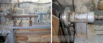
DIY lathe headstock
The headstock for a lathe can be made independently without any problems.
For this purpose you will need:
- Wooden plank.
- Plywood, ten millimeters thick.
- A thin sheet of metal that is cut with special scissors.
It is much easier to make a headstock with your own hands if the basis of this device is an ordinary unnecessary drill. After this, it will only be necessary to make a stand, which will subsequently be the mounting platform for the drill, which has a strict horizontal axis.
The middle of the front and middle of the tailstock must be securely fastened, this is extremely necessary. For the tailstock, it is necessary to establish in advance the limits of the possibilities of wrapping along the axis and rigidly securing it in place.
The power of the electric motor should be selected independently, based on the purpose of the turning device. Although the engine power does not need to be less than 250 W. Otherwise, it will not be possible to turn out any necessary parts.
Which cutting tool to use
The production of parts on such machines is carried out using special turning tools. They must provide the following:
Types and purposes of turning tools
Turning cutters are classified according to different parameters. Depending on the type of work performed, they can be cutting, passing, shaped, scoring, etc. Cutters are made from various materials - diamonds, tungsten, titanium-tungsten and others. Depending on the design, these tools can be one-piece, prefabricated or combined.
The choice of a specific type of tool is carried out taking into account the modes of the work operations being carried out, the hardness of the workpiece, the geometric parameters of the cutting part and other characteristics.
Related video: Metal turning
Do-it-yourself ball for a lathe
Here is one of the links to the balloon that I liked. » >
Damn, this is even more interesting than proxon, here you just need to make equipment for replaceable plates
Aspirant wrote: Damn, this is even more interesting than proxon,
Much more interesting. That's where else to find time to make it.
I have a designer part-time. While he is busy, how he will free himself (by the end of September from the gardens) is a mystery. then at the factory or I’ll create it myself
Aspirant wrote: I have a designer part-time
It’s good for you, but I’m my own Petlyura. And a designer, and a draftsman, and a mechanic, and a turner, etc.
Yes, I’m just like that, I just realized that I can’t do everything myself, so I’m turning to pensioners because they are an order of magnitude more experienced, wiser and smarter than us young people in everything. only we are nimble and that’s what makes us different
I can’t say this about myself.
Aspirant wrote: On Wednesday I received a little ball I’m thinking of adapting it to a Corvette or making an analogue for a large machine, I’m bragging
If possible, give the dimensions of this device. Here's a video about the spherotochka Here's more
At the request of the workers, I am developing the topic and posting drawings of the balloon I bought. Request to comrades who are at the chipmaker - make links to this topic, I want to encourage people to benefit the cause
and this is a photo of the glands themselves
And here is the assembled ball in position for turning external spheres
And now the main thing is that without a rectangular support, the cutting point coincides with the axis of rotation of the workpiece on the Corvette 400 when installing the equipment instead of a tool holder
Devices for processing spheres
Ball turning
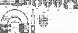
When people talk about spherical surfaces, they usually think of a ball. In reality, we will talk about spheres, which are sections of the general surface of a part. Such parts having spheres (spherical and torus surfaces) include: dies, punches, ball joints, footplates, taps, lenses, tips, fittings, nipples, supports, hubs, ball joints, valves, rollers, rolls, flywheels, press -shapes, worm gears, etc.
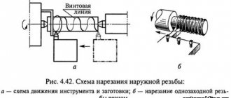
Let us divide all spheres into convex and concave and classify them based on their location on the surface of the part. In Fig. 49 shows convex ones, and in Fig. 50 concave spheres. Some spheres, by their location, have a common axis of symmetry with the part (Fig. 49, b - her Fig. 50, a - c), others do not have a common axis of symmetry with the part (Fig. 49, a, g, h and Fig. 50 , d - h).
Rice. 49. Convex spheres
Processing the spheres represents the definition of difficulty. Devices for processing and measuring precision spheres of large and small radii (1 ... 200 mm), having a 6th grade and a surface roughness of 0.32 ... 0.04 microns, have been introduced into production. The technological process of processing spheres is reduced to turning, grinding, polishing and diamond smoothing.
Rice. 50. Concave spheres
In order to understand the variety of devices and better know which devices to use in which case, we classify them according to the nature of the movement of the cutter: devices with translational movement of the cutter (Fig. 51, a, b) and with rotational movement (Fig. 51, c).
Rice. 51. Devices for translational (a, b) and rotational (c) movement of the cutter
Devices with a translational movement of the cutter are less versatile and have more disadvantages compared to devices with a rotary movement. Continuous changes in the plan angles of the cutter during its translational movement along the curved surface of the part and wear of the cutting edges lead to distortion of the geometry of the sphere and an increase in surface roughness. In addition, the size of the sphere surface that can be processed without turning the cutter is limited. For example, with a plan angle of 60°, you can machine the surface of the sphere at no more than an angle of 120° (Fig. 51, a).
To reduce these disadvantages, in devices with translational movement of the cutter, a roller or a spherical tip is used instead of a probe, and a circular cutting edge of a certain radius is sharpened on the cutter (Fig. 51, b). In this case, the radius ratio is maintained according to the formula
R1 + R2 = R3+ R4, where, respectively, the radii are: R1 - roller; R2 - copier; R3 - incisor; R4 - spheres.
Replacing the stylus with a roller or spherical tip introduces additional difficulties associated with the manufacture of cutters. At the same time, the general disadvantage of such devices is not eliminated due to the presence of gaps in the device mechanisms. There remains a distortion of the geometry of the sphere in the zone of the O - O axis (Fig. 51, a, b). These gaps manifest themselves when the direction of movement of the mechanism carrying the cutter changes, and when the direction of pressure on the roller or probe changes when sliding along the copier.
In addition, when processing a sphere with devices with translational movement of the cutter, it is difficult to control its shape. To do this, it would seem that it is enough to grind the sphere first and, by measuring, make sure that its geometric shape is correct. But this technique does not give the desired results, since during preliminary grooving the sphere turns out to be distorted. Measurements without distortion can be made only when the sphere is machined to the required size.
Devices with translational movement of the tool are not suitable for performing diamond smoothing, since the convex working part of the diamond in the form of a sphere or cylinder is limited in size and it can smooth only with a constant orientation relative to the surface being processed.
Devices with rotational movement of the cutter (Fig. 51, c) do not have these disadvantages. The cutting angles remain unchanged. Wear of the cutter does not cause distortion of the shape of the sphere and can only affect the change in the size of the sphere, which is easily eliminated by adjusting the machine. Such devices are convenient for the use of diamond burnishing and are becoming increasingly used.
We make a wood milling machine for a home workshop
Milling machines are necessary for working with shaped wood parts. They are used for flat milling and profile processing. Professional equipment is multifunctional and costs a lot of money, so more and more “homemade” people are assembling such equipment for workshops and garages on their own.
Small DIY milling machine
The set of homemade wood milling machines includes:
- Drive mechanism. This is an engine whose power ranges from 1-2 kW. With such a motor, you can use various tools to work with wood without fear of failure.
- Lift for adjustment. Typically, it includes a body, sliding skids, carriages, a fixing screw and a threaded axle. During operation, the carriage moves up and down, and a screw is needed to fix it at the required level.
- Support. The table is made from solid wood.
Before assembly, be sure to draw up a detailed drawing with all dimensions. For manual wood milling machines, you need to think through everything in advance down to the smallest detail.
3D model of a table for a manual machine Equipment components Dimensions of the working element Cutting on a milling machine
The sequence of self-assembly of a convenient and practical wood milling machine for a home workshop is described in the video instructions:
If you are thinking about buying your own equipment rather than assembling it yourself, then to understand how much a manual wood router costs, look at the table with models and prices:
| Model name | Specifications | |
| Milling table Kraton MT-20-01 | site size | 64 by 36 cm |
| possibility of vertical work | There is | |
| equipment weight | 15.7 kg | |
| Milling table Kraton MT-20-01 | ||
| Milling machine Corvette-83 90830 | engine power | 750 W |
| transmission type | belt | |
| spindle speed | 11,000 rpm | |
| vertical stroke | 2.2 cm | |
| spindle diameter | 12.7mm | |
| Milling machine Corvette-83 90830 |
Making a CNC milling machine with your own hands
You can make your own numerical control equipment with your own hands. To do this, select suitable drawings of a CNC wood milling machine. You will need to assemble the model with your own hands strictly according to them.
Ready-made machine for a home workshop Equipment components Detailed assembly diagram Model of multifunctional equipment
Wood milling machines must have great strength, so it is better to take a rectangular beam mounted on guides as a basis. The lifespan of home equipment and its performance depend on proper assembly. Watch the video instructions for making such a device:
Below are photos of finished models of CNC woodworking machines with your own hands from professional “homemade” ones:
Cutting modes: what are they?
This is a whole complex of characteristics that determine the conditions for carrying out a turning operation. According to the technological routes, the processing of any element (especially complex in shape) is carried out in several transitions, each of which requires its own drawings, dimensions and tolerances, equipment and accessories. Having calculated and/or selected all these parameters once for the first workpiece, in the future you will be able to substitute them by default - when producing the second, fifth, hundredth part - and thus minimize the time for preparing the machine and simplify quality control, that is, optimize the production process .
The main indicators include depth, speed, feed, the list of additional ones includes the mass of the object, allowances, the frequency with which the spindle rotates, and, in principle, any characteristic that affects the result of processing. And it is important to choose those that will provide the best final accuracy, roughness and economic feasibility.
There are several ways to calculate cutting conditions when turning:
The first is quite accurate and, before the advent of powerful computer technology, was considered the most convenient. According to it, all calculations were carried out on the basis of the equipment’s passport data: engine power, spindle speed and other indicators were substituted into already verified empirical expressions and the required characteristics were obtained.
With the development of specialized software, the calculation task has been significantly simplified - all operations are performed by a machine, faster than a person and with a much lower probability of making mistakes.
When you don’t have a computer or formulas at hand, but you do have experience, you can determine the appropriate criteria based on normative and reference data from the tables. But for this it is necessary to take into account all changes in values, even the slightest, which is not always convenient in production conditions.
Turn a ball Ø72mm for current. Is it real on a CNC machine?
I thought at home, there is no Internet there, so I wrote from memory and the dimensions do not correspond a little, but I think the meaning should be clear.
Ball preparation technology.
You need to make a ball, one piece.
1. Take a blank with a diameter of 80mm and a length of 80mm. We press it into the cams (the first cam/installation) and sharpen it with a 35* cutter. Afterwards, an allowance remains, clamped in the fists. Approximately 13mm (highlighted in pink).
2. We install a stop in the spindle of the machine, if this is possible. The end of the stop must be flat without centering, as well as without bulges or bulges. Knowing the coordinates of the stop, it is not difficult to calculate the center of the ball, as well as Z0.
We sharpen the second setting in the cams.
If the option with a stop is not possible, you can do it in a more sophisticated way. To do this, we clamp a ring with a diameter of approximately 70 mm into the jaws and sharpen the radius groove (groove) with the required cutter. The groove should be in such a way that the ball is grasped as accurately as possible. Those. groove radius 74/2=37mm, and maximum diameter 74mm. We subsequently clamp our hemisphere into this groove.
We know the dimensions and position of the groove; it will not be difficult to calculate Z0.
In general, we work at approximately this rhythm. Everything should work out.
PS
The drawing schematically indicated how everything should happen. Please don't criticize me for sloppy lines.
I was interested in hardening for a reason. Why the complexity of processing in the centers if there are no thermals?
What is the batch size of these products?
Spherotochka for a lathe – Machine tools, welding, metalworking
To expand the functionality of the lathe, it is recommended to use special milling parts. They are manufactured in a variety of variants, which makes it possible to perform a variety of tasks in the field of parts processing. Milling fixtures for a lathe come in several types; the complexity of their design depends on the characteristics of the task at hand.
Modern equipment is head and shoulders above Soviet analogues; the metal used in the construction is of high quality, strength and durability. The fasteners of the unit have quality certificates and are also durable.
To carry out work on such a unit, craftsmen require a specialized medical examination; the equipment requires attentiveness, scrupulousness, and good vision from the specialist. The finishing process of any metal fragment takes place in several stages.
The device for a metal lathe is manufactured in three varieties:
- The first option is special. With its help, the operational capabilities of the unit are increased.
- The second option of additional parts is used to fix the tool.
- Thanks to the use of the third option of equipment, parts that are to be processed on a lathe are fixed.
Using various equipment, a wide range of work performed by the turning unit is provided:
- metal fragments are fixed qualitatively;
- the accuracy of processing metal workpieces increases;
- it becomes possible to perform milling operations correctly;
- The process of processing metal parts is accelerated.
The milling fixture for a lathe is manufactured in factories. It is characterized by a high level of strength, this feature ensures its long-term use.
Thanks to the use of high quality materials for the manufacture of equipment, its service life is significantly extended. At home, it is easy to use a homemade device for a metal lathe. Most often, a special attachment is used, thanks to which craftsmen can perform the following operations:
- mill planes;
- select grooves and grooves;
- process the base using face and end mills;
- contour processing of various products.
Milling attachment for lathe
An attachment for a lathe makes it possible not only to expand the scope of application of the equipment, but also to carry out metalworking work with maximum precision.
What equipment should I use?
It is necessary to select a device for a lathe in accordance with the tasks assigned to the operator. Most often, specialists use several parts.
Vibration mounts - ideal for metal lathes and grinding equipment. With its help, the quality of part processing is increased. Thanks to such a product, vibration is significantly reduced; this operating principle has a positive effect on the life of the machine.
Centers. Lathe units have a universal design, but it forces the master to use special equipment. Thanks to the centers, the highest quality setting of precision parameters is ensured.
Ammo. The device is most often used in woodworking units. Using such equipment, the most reliable fixation of the fragment is ensured. The cartridge is secured using a bolt through a clamp.
Fists. This type of part is characterized by the presence of several design options. With their help, reliable fixation of the part on the outside of the shaft is ensured.
Cam for lathe
Jaw lathe chucks - parts are used for fixing workpieces that have a rectangular, cylindrical or shaped shape. There are several types of chucks - two-jaw, three-jaw and four-jaw. The use of products with various types of turning installations is allowed.
The selection of equipment must take place after studying all the advantages of the unit, as well as analyzing the conditions of the room where the equipment will be installed. Additionally, you should determine where the cabinet with metal fragments and finished products will be placed.
Additional details
The unit has minor, but quite important details in its design.
Lunetov. They are used in structures that process metal and wood. The scope of application of such units are milling, turning and grinding locks. The installations support long workpieces.
Tool holders. The units are used in metal lathes. Thanks to these devices, the cutters are secured to the caliper. The device has transverse and longitudinal movement in relation to the metal fragment.
Accessories for metal-cutting machines are produced in a wide range; this feature makes it possible for turners to select the most appropriate option in accordance with the tasks assigned.
The individual equipment passport always specifies the technical characteristics and departmental requirements for the operation of the installation on the territory of the enterprise. It is necessary to strictly comply with all conditions when installing the unit.
Failure to comply with safety precautions, as well as technical specifications, can lead to disruption of the technological process, as well as injuries to working personnel.
Features of using jaw chucks
The most commonly used chucks in metalworking machines are jaw chucks. In such a case, it is recommended to use two-jaw lathe devices. They are the best option if there is no need for the most precise centering.
With their use, small parts, castings, and forgings are fixed. Jaw chucks fix parts that have strictly defined geometric parameters. If it is necessary to process workpieces of arbitrary configuration, this requires the use of four-jaw chucks.
Homemade devices are characterized by the appearance of an individual drive; this design allows for the simplest possible centering.
When using chucks with such a drive, there is a chance to machine rectangular and asymmetrical parts. Square bars are processed using self-centering fixtures, which are equipped with four jaws.
Three-jaw chucks are often used in metalworking machines.
Three jaw chuck for lathe
With their help, high-quality work with rods with a large cross-section is ensured.
If three-jaw chucks are actively used, this will lead to a loss of accuracy, which is their only drawback.
Advice from the experts
For large cross-sections of workpieces, it is recommended to use rotating and thrust centers. With their help, efficient work on metal is ensured; the workpiece is placed in the center only after it has been centered.
For this purpose, it is necessary to make special holes at the ends of the workpiece shaft. Thanks to the use of a clamp, the part receives rotating torque from the spindle.
Milling equipment is distinguished by scrupulousness and jewellery, the work takes place in a uniform rhythm, and the master is required to constantly monitor the movement of the shaft.
The cartridges, which are made of the drive type, are characterized by a small body. It is installed on the spindle of lathes.
The end part of the unit is equipped with a pressed pin, which is used to send the required torque to the clamp. The clamp is fixed to the part being processed using a bolt.
The use of a driving chuck is not carried out when the center hole of the workpiece is large. In this case, it becomes necessary to use a rotating center with a special design.
The working part of the additional parts is characterized by a pronounced corrugated surface. If, when processing a workpiece, it is necessary to cut off a layer of large thickness, then it is necessary to install a rotating rear center on the machine. It allows the equipment to operate at high speed.
Accessories for machine tools can significantly simplify the process of processing metal workpieces. To ensure quality work, it is recommended to select the product correctly. To this end, the turner must follow certain rules. He can buy a ready-made device or make it himself.
on topic: Useful accessory for a lathe
Turning for Beginners | Machines and tools
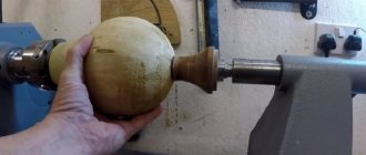
How to carve a ball from wood
I was looking for information on home lathes and came across this video. I was truly fascinated by the beauty and simplicity of execution.
No duplicates found
It's beautiful, but he hasn't heard about safety precautions
Works for a long time, experienced. The fear is already disappearing. Several people in our workshop have already lost their fingers. Some on a band saw, some on a milling cutter, some decided to clean the edger without turning off the machine. What about the machine, the photocells saw something, a milling cutter.
They don’t think that during work they can put something in the gap other than the edge. Over the course of 7 years, 5 people cut their fingers like this. One was not afraid of the forklift. He sat down with the load on the forks and didn’t even hold on. The load fell. loader too. The legs were collected in parts, he will no longer walk, the boy is about 25 years old.
Oh, this is a disregard for safety precautions.
The guy was talking. At the plant he worked as an electrician in the stamping shop. It is necessary to shake off the garbage from the press; many workers sweep it away with their hands. They don’t use special brushes, don’t turn off the press first, and don’t remove their foot from the pedal. Just click and that's it. There will be no hand. A couple of hundred tons will be flattened. Half of them don’t have at least one finger. And they continue to climb.
We need to introduce protection from idiots everywhere. It doesn't work anymore if you're a fool) Here's a good example: https://.com/watch?v=dFYAt_1E-Vo
and don’t underestimate idiots, they will remove this mechanism so that it doesn’t accidentally break)
The fact of the matter is that no. Multi-ton drums stop instantly, and such saws are just fluff for them.
I also thought that this was useful know-how, until smart people convinced me otherwise. That everything was invented a long time ago and is not disposable
For example, on my CNC router, a cutter with 24k revolutions stops instantly if something happens. Although I don't think it's good for her.
But this is if the machine, for example, has lost connection with the servos or with the pantograph itself. It assumes that something has fallen off and needs to be blocked at any cost.
And if you just enter the work area, the photocells will work and the stop will be set for 4 seconds. Although it can be reduced.
Inside there are brake discs and pads on springs. When the engine is turned on, the electromagnets remove the brake; if there is an emergency, the electromagnets are turned off and the springs press the pads onto the disc. But this is simplified, there is something more complicated. I don’t remember brake couplings or whatever they are called correctly.
This Master has so much experience working on machines that he knows how and where it is dangerous, and where it is just a piece of wood spinning. his name is Alexander Kutuzov. Find it on the net before discussing his skills.
All his knowledge of where it is dangerous and where it is not has nothing to do with it. The photo clearly shows that it's complete crap. Long cuffs near the rotating drum.
I'm not judging his skills, I'm judging his adherence to safety.
As an experienced cabinetmaker with all his fingers (tfu-tfu) with 17 years of experience, as well as a woodworking process engineer, knowing this master personally, I declare! There is no safety violation in the video.
I advise you to take a new safety course. And the fact that all the fingers are intact is good; it would be good if it remained that way. But failure to comply with safety regulations is no joke. I don't intend to argue anymore.
I advise you not to advise people who know and can do a lot in their element. We look at 2.20 and see that the sleeves are fastened as they should be, so that chips do not get in. I know TV by heart and at one time I taught school in TV. It’s bad that amateurs try to talk about something they don’t understand.
How many times have I seen professionals neglect safety precautions? 12 years ago I was working at a factory and a man did not button up his overalls. It’s hot, and he’s been working for so many years, he’s a pro. The edge of the clothes got caught under the conveyor belt, it was wrapped up in an instant, only the legs were sticking out.
Fatal accident. The other one is also a pro, the fences interfere with cleaning the workplace, screw them. He fell into the debarking drum, within seconds there was a bag of bones, there was no chance of survival. The welder worked for about 30 years, a professional, dismantled an old conveyor, 5 meters high.
I got distracted, got lost in thought, and cut off the fittings on which the disabled man was sitting. Vanya also worked in a pilot for 30 years, he has a lot of experience, he removed the limit switch on the folding visor, it’s in the way, there’s not enough space with it, but he’s a pro. It bit the knife and, like a guillotine on the finger, tore out a piece right down to the bone.
The finger was saved, but it hardly bends.
At the new job, as I wrote above, they mostly left fingers, broken legs, and one finger pressed under pneumatic clamps. And all because they fucked all TB, they're pros.
The photo clearly shows the sleeve cuffs and the drum, this is a violation. As I understand it, you are simply shielding him because you know him. It would be better to advise him to be more attentive, so that he could continue to please with beautiful crafts.
The degree of accuracy and quality of the processed surface depend on the skill of the master to work on a lathe, which does not have a Numerical Program Control system.
However, some types of parts are almost impossible to create by turning with a cutter without auxiliary equipment.
If there is a need to establish mass production with high processing accuracy, you cannot do without auxiliary equipment. How to make a ball on a lathe, and what equipment is used?
Method of turning on a lathe with a standard support
For large-scale production, a special fixture is created or a CNC system is used. If there is a need to create just a few balls by turning, then the work can be done on a lathe that has a tailstock.