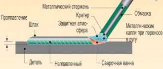
Over the past couple of decades, there have been major changes in the development of welding technologies. The most popular equipment has become the inverter - a technologically advanced and modern device that has many advantages compared to classic welding. In addition to more advanced technical solutions from transformers and rectifiers, it also compares favorably in cost.
At the center of the technical solution is a microcircuit. It was these small elements that gave manufacturers the opportunity to pack equipment with extensive functionality and radically reduce the weight and size of the installation. But there is also another side to the coin. It lies in the fact that technically more complex devices fail more often. So, the main faults and repairs of inverter welding machines with your own hands.
The welding machine welds intermittently
But at the same time, the welding inverter also has a more complex design, compared to previous models of welding equipment, which increases the chance of a malfunction occurring during its operation.
As a rule, all malfunctions of the welding inverter can be divided into two groups:
- malfunctions associated with improper operation of the electronic “stuffing” of the device
- malfunctions associated with incorrect choice of operating mode.
The second type of malfunction occurs most often, therefore, before contacting a specialized workshop or starting to disassemble the device yourself in order to identify a breakdown, you need to check whether all operating mode settings are set correctly, and in addition, you should read the operating instructions for this device again, to determine if you are making any mistakes while working. Most manufacturers, when drawing up instructions, indicate the causes of welding inverter malfunctions that may occur during operation, and also describe how these malfunctions can be eliminated independently.
Causes of breakdowns of welding inverters and options for eliminating them.
There are a number of typical faults that occur when it comes to welding inverters:
- instability of the welding arc and strong spattering of metal;
- welding electrode sticking;
- lack of welding process when the machine is turned on;
- lack of response from the device when it is turned on.
Let us consider in more detail why this or that situation may arise, and what can be done in the event of any malfunction of welding inverters.
- Instability of the welding arc and strong spattering of metal.
This malfunction can occur if you select the wrong current when welding. As a rule, the welding current is selected in accordance with the type and size of the electrode used for welding. But here it is necessary to remember one more important rule: the selected current must correspond to the speed at which welding is carried out. If the welding speed decreases during operation, then the welding current must be reduced.
- Welding electrode sticking.
In fact, there may be several reasons for this type of malfunction. It is quite possible that during welding the voltage in the network suddenly decreased, which led to severe sticking of the welding electrode. It can also “stick” if the inverter is connected to the network with a cable with too small a cross-section. Another reason for this “behavior” of the electrode may be poor contact of the electrode with the surface to be welded due to the fact that the surface has undergone oxidation due to exposure to atmospheric oxygen. In this case, welding must be stopped and the surface of the part must be cleaned of film.
- Lack of welding process when the machine is turned on.
In the vast majority of cases, this behavior of the welding inverter can be explained by the lack of mass on the surface of the part being welded. In addition, it would be useful to check the condition of the welding cable - it may be damaged. This situation occurs quite often if the part being welded is heavy, as a result of which the part falling onto the wire can damage its integrity.
- The device does not respond when turned on.
If nothing happens when you turn on the welding inverter, then the cause of such a malfunction should be sought, in many cases, not in the inverter itself, but in the electrical network to which it is connected. The mains voltage may be too low and therefore the device cannot operate. Another reason that the device does not turn on may be an incorrectly selected circuit breaker installed in the panel. A weak switch can turn off when the inverter is turned on. In addition, turning off the device can lead to a loss of electricity throughout the house.
In addition to the indicated malfunctions, there are also interruptions in the operation of the welding inverter, which are not related to the breakdown of the device, but are a consequence of the fairly high-quality and timely operation of the protection systems with which the inverter is equipped. For example, during prolonged continuous operation, the inverter may turn off spontaneously. This happens if the device overheats and the temperature protection trips. In this case, you should stop the welding process for about 20-30 minutes, allow the device to cool, after which work can be continued.
Repair and diagnostics of welding machine malfunctions
When a welding machine breaks down, work plans are disrupted. It is necessary to find the cause of the breakdown and eliminate it. If the equipment is no longer under warranty, it is not necessary to contact the service center. Some problems can be recognized and repaired on your own. In this article we will look at possible malfunctions in different inverter devices, diagnostic methods and repair techniques. We’ll also touch on which welding machines are best to buy in order to be less likely to experience breakdowns.
In this article:
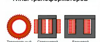
To increase the chances of success when repairing a welding machine, you need to understand a little about its structure. All types of equipment for MMA, TIG and MIG welding have a common inverter unit, only in the case of manual arc welding the process is carried out with a consumable electrode in a coating, and the argon torch has a non-consumable tungsten electrode and a channel for supplying shielding gas. Semi-automatic machines additionally have a drum and a feed mechanism.
The inverter unit, which produces converted direct current for welding, consists of the following elements:
- Primary rectifier
. It is a diode bridge that rectifies the current flowing from the socket into the device. To prevent the bridge from overheating, it has a temperature sensor that cuts off the circuit when it reaches 90 degrees. Air cooling is implemented in the form of a supply fan. - Capacitor filter
. It has a parallel connection to the bridge and smooths out pulses from alternating voltage. - Noise filter
. During operation of the inverter device, electromagnetic waves are created that can interfere with the operation of other equipment connected to the common network. The filter eliminates the negative impact. - High frequency transformer
. Increases the frequency of alternating current, lowering the voltage. - Secondary rectifier
. Installed at the exit. The diode bridge has a high opening/closing speed. Radiators are provided to remove heat. Two terminals for connecting welding cables extend from it.
The main element is the control board with keys. These are transistor switches of the Mosfet type or more modern ones - IGBT. They contain 2 or 4 keys, respectively divided into half-bridge and bridge. Provide economical power consumption, load and fine settings of welding current.
The essence of the inverter's operation is to receive alternating current from the mains with a frequency of 50 Hz, rectify it, and convert it back into alternating current, but with a frequency that has already been increased many times. At the output, the current is rectified again and welding is carried out with direct current.
Diagnosis of breakdowns of inverter welding machines
When the welding machine does not work, smoke comes out of it, a burning smell is felt, diagnostics are necessary. At home this is done like this:
- Disconnect the device from the network
- Unscrew the side cover screws
- Inspect boards, capacitors, transistors, terminals
- Tug the wires with your hand
You need to look for black marks (if something is burned) or a weak, loose contact. Most often, inverters stop working due to burnout of one of the elements. Then the device does not turn on completely or hums, but does not cook. The task is to find the problematic module and replace it or restore contact.
If a visual inspection does not yield anything, the diagnosis continues using a multimeter. A non-specialist should not climb into an inverter that is energized. Checking the resistance and declared parameters for voltage and current is the job of specialists. An amateur can only ring an electrical circuit that is disconnected from power.
To do this, set the switch in the multimeter to ringing mode. This is often indicated by a bell or continuity check icon. Depending on the radio component that you plan to check, various testing methods are used, as well as selecting parameters on a multimeter. In a general sense, it is necessary to lean one contact of the part in one probe, and the other - against the other. A unit should light up on the multimeter screen (there is a contact or another designation). If the display shows zeros, you have found a burnt-out element (depending on the type of radio component).
It needs to be unsoldered and replaced with a new one with a similar marking. It is better to perform soldering using a station with a desoldering pump, so as not to fill the adjacent contacts with solder, creating a path for a short circuit after switching on:
- Heat the legs of the burnt element and stir it in the printed circuit board, remove it out
- Degrease the joint with rosin
- Insert the new element into the holes on the PCB
- Apply solder and wait until it hardens
To test diode bridges with a tester, as a rule, they will first need to be removed from the general circuit, because sometimes they are paralleled, which makes it impossible to correctly identify a faulty bridge.
These are the general principles of diagnosis and repair. Next, we will consider breakdowns of varying degrees of complexity, possible causes and solutions.
Specific symptoms of malfunction and repair methods
Welding inverter breakdowns can be divided according to the degree of complexity. Some can be easily eliminated with your own hands at home.
The welding inverter sparks, but does not weld HideRead more
The problem is characterized by the absence of a welding arc, but slight contact appears when the electrode is passed over the workpiece. This is a simple failure due to a weak connection. Check the rigidity of the connection of the welding cable and ground to the sockets in the machine. If they are loose, secure them. Check the ground connection to the product. If it is a homemade hook, it is better to grab it by welding. Even if you use a crocodile, move it to improve contact.
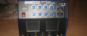
The electrode can spark due to incorrectly selected current strength. Sometimes the “twist” accidentally gets knocked down when rearranging the device if it gets touched by clothing. To prevent this from happening, use inverters with a protective shield covering the control panel. This is available, for example, in the EWM PICO 160 CEL PULS MMA welding machine
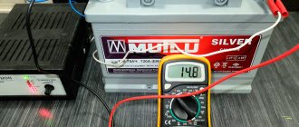
The inverter may spark but not cook due to low input voltage. Check the readings at the outlet with a tester. If they are below 220 V, then a voltage stabilizer or welding machines designed to work with a reduced incoming current will help. For example, the RESANTA SAI-220 welding inverter welds at an input voltage of 140 V. Of course, it does not produce 220 A with low input current parameters, but it will be possible to weld sheets of iron to gates, weld a tank for a summer house, etc.
The greater the voltage drop, the lower the welding current. Here is a table of voltage per board when welding with an inverter with a limit of 160 A, showing the interdependence of the parameters.
| Mains voltage, V | Resistance, Ohm | Welding current, A |
| 220 | 0 | 160 |
| 210 | 1 | 150 |
| 197 | 2 | 145 |
| 180 | 3 | 115 |
| 165 | 4 | 105 |
A long power cord leads to increased resistance and reduces the incoming current. Reconnecting to a closer outlet with a short wire or using inverters designed for lower voltage will help here.
Long welding cables of the workpiece and the electrode holder also act as increased resistance, reducing the current strength. Try connecting short cables of 3-4 m and repeat arcing.
The electrode sticks to the metal HideRead More
The electrode can stick for the same reasons as sparking: low welding current, long power cord and welding cables, low voltage in the network. But sometimes this happens when welding thin metal. A welding current of 60-80 A burns through the metal, and a low current of 30-50 A causes the electrode to stick.
Then choose a welding inverter with an anti-stick function. For example, ESAB BUDDY ARC has a special mode that, at reduced operating currents, “feels” the moment of electrode sticking and briefly supplies an increased current. The action lasts a second, after which the current strength drops to the one set by the welder. This is enough to prevent the electrode from sticking and from burning the metal.
The current is not regulated HideRead more
When it is impossible to change the current, the problem is in the switch itself. It is mechanically or electrically faulty. Remove the plastic “twist” and try turning the rod with pliers.
If the regulator does not respond, then you need to ring its contacts with a multimeter. In the event of a break, the regulator is replaced entirely by unsoldering the terminals and unscrewing it from the housing. Install a new regulator and check the operation of the device.
Why does the welding machine turn on but not weld? HideRead More
If the “Power” light is on and the fan is humming, but the welding machine is not welding, it is most likely overheated. Each inverter has its own on-duration (PO) or load duration (LO). It is indicated in % and means how many of 10 minutes the equipment can operate continuously at a certain current.
Household models most often have a PV indicator of 30-40%, so after boiling for 5-10 minutes in a row, the device goes into protection so as not to burn out. Wait 20-30 minutes until the device has cooled down and try cooking again. If long-term regular welding work is required, use devices with a duty cycle of 60-100%, such as the BARSVELD Profi ARC-507 D inverter for a three-phase network or the TORUS-250 Extra welder for a two-phase network. Among semi-automatic machines, the Aurora PRO OVERMAN 200 has proven itself well in terms of load duration.
The welding inverter does not turn on/does not work HideRead More
If the lights on the inverter do not light up, the power cord may be broken. Disassemble the case and check the reliability of the network cable contacts. The second probable reason is a large layer of dust on the board; the device went into protection to avoid a short circuit. Disassemble the housing and blow out the device with compressed air from the compressor. If you don't have a compressor, use a soft brush.
When the inverter does not turn on, check the input diode bridge and power capacitors.
Welding Tips
To prevent welding machines from breaking, it is important to follow a number of simple tips:
- Select the correct welding modes
- Periodically check the tightness of the contacts of the welding cables and the power cable
- At low voltage, use devices designed for sag
- Do not overload the inverter beyond its rated capacity. Let the equipment cool down
- Make sure that the body is not covered on top with work clothes or other materials that retard heat transfer
- Do not place the inverter in dusty areas
If you regularly weld in difficult construction conditions, use welding machines with body protection with rubber pads, such as the argon model Svarog REAL TIG 200 or MMA semi-automatic ESAB Rebel EMP
You can choose reliable semi-automatic machines, TIG inverters and RDS devices from trusted brands EWM, Fronius, Lincoln Electric, ESAB. Or pay attention to the “professional” and “semi-professional” categories, where models are initially designed for longer work. Then you will have to deal with breakdowns and repair them less often.
Answers to questions: how to repair a welding machine with your own hands?
How often should the inverter be blown out of dust? HideMore details
This depends on the degree of dust in the room where it is located. If abrasive cutting of metal, grinding, or polishing of stainless steel is carried out nearby, then it is recommended to clean it weekly. Blowing is necessary every month, or better yet every week. In normal garage conditions, preventive blowing is sufficient once every 6 months.
What to do if the inverter cooks poorly? HideMore details
Check the voltage in the outlet, it must comply with GOST. If it is low, try brewing at a different time of day. If the voltage is normal, try to connect the device to a network with a minimum wire length (220 V network wires create additional resistance).
What and how to remove dust from the inverter? HideMore details
Any compressor will do this. Most models do not require any disassembly. There is perforation on the front side for ventilation. Place the hose on it and turn on the air supply. Dust will come out from the back side behind the fan.
What to do if the welding machine rattles a lot when welding? HideMore details
For transformers, this is a normal operating sound. Nothing can be done. If the inverter begins to rattle, check the tightness of the housing. Often the screws become loose due to vibration and the body begins to resonate.
What to do if the ground cable/holder socket becomes loose? HideMore details
If the connector is loose, it will create poor contact, which will lead to damage to the device. The connector needs to be replaced. interferes with cooking. The connector can be replaced by accessing the back side. Buy exactly the same one for your inverter model.
There are still questions
Leave your contact details and we will contact you shortly
Feedback
Return to list
There is not enough voltage for the welding machine
Probably, many people are familiar with the situation when, when welding metal with a household machine, the electrode “sticks” and a welding arc does not form. This happens due to insufficient voltage in the network, because you can cook with an electrode with a diameter of 3 mm only at a voltage of at least 200 V, and 2 mm - 180 V. But sometimes when measuring the voltage in the outlet you can find much lower values - up to 160-150 B. The problem of low voltage in the network in many localities can be associated with various reasons:
- wear of distribution wires, which leads to zero burnout and voltage imbalance across phases;
- the presence of a low-power transformer substation that cannot cope with the increased load or increase in the number of consumers;
- phase imbalance on the transformer and others.
Why does the electrode stick when welding?
Electrodes are the main consumables for welding. They are produced in a wide variety, since each model is designed for its own type of metal and special conditions of use. Correctly selected surfacing material and the mode of its use protects against many negative phenomena that lead to defects during welding. This requires not only adherence to the technical part, but also the skill of a master. After all, the reasons why the electrode sticks during welding can be completely different.
Electrode sticking when welding with an inverter
The consumables themselves undergo various degrees of control during production, so that customers are often supplied with high-quality, proven items. In the future, all that remains is to choose them correctly and apply them to achieve the desired result. Selecting reliable products with quality certificates will help solve many problems, but the electrodes may be damaged due to improper storage or transportation, so this factor should also be taken into account before starting work. Sticking of electrodes when welding with an inverter is extremely undesirable when it comes to critical structures, as this spoils the structure of the seam and harms the welding machine itself.
One of the reasons for filler material sticking to the base metal is insufficient coating of the welding electrode. The end, as a rule, is the most vulnerable point and the coating is often sprinkled here. Without it, the arc is quite unstable and unprotected, so sticking in this case will be quite common. Even increasing the welding current will not help here. Problems with the coating can also arise in another way, since it often accumulates moisture whenever possible. In addition to the fact that you should not weld with wet electrodes due to the potentially high hydrogen content in the weld, which will lead to the formation of cracks, it will also provoke sticking. One of the reasons why an electrode sticks is that it is damp. If the coating has absorbed a large amount of moisture, then it is quite difficult for the electric arc to ignite. Increasing the welding current also does not help here, therefore, it is better to choose other materials for the process.
Lack of welding electrode coating
One of the most common reasons why an electrode sticks when welding with an inverter is an incorrectly selected mode. Many craftsmen are afraid to burn out the base metal, so they try to choose a setting that is a little weaker than it should be. Insufficient current means there is not enough energy to ignite the arc. Even if it lights up for a while, it quickly disappears and the electrode sticks again. It is for this reason that it is worth paying attention to precise welding modes and using techniques with precise adjustment of parameters, especially when the thinnest electrodes are used.
Selecting the correct mode when welding with an inverter
Lack of experience very often becomes the reason why electrodes stick when welding, since even with correctly selected parameters nothing may come of it. This requires experience in igniting a specific electrode diameter, as well as knowledge of the nuances of operation in various positions. Here you need to confidently catch the arc and its position. Otherwise, it will either be interrupted if the electrode is too high, or stick if it is too low. The height of the arc depends on the specific brand and its diameter. Considering that experts recommend keeping the arc as low as possible, beginners often reduce the whole situation to the fact that the electrode is constantly sticking.
The most common reason why the electrode sticks when welding with an inverter is the low quality of the consumables. Brands that are too cheap often do not perform well and can carry with them a whole range of negative aspects.
Recommendations
One of the easiest ways to overcome this problem is the additional “anti-stick electrode” function, which is available on modern welding machines. Naturally, it will not help in the most difficult cases, but it will make their use much simpler and easier.
You also need to pay attention to the correct selection of the electrodes themselves and the modes of their use. This is the main way to avoid sticking. After all, sometimes it is enough just to raise the current to the required level and the arc will stabilize.
Before using consumables, they should be dried and calcined to remove moisture. Even if these are new consumables, these procedures should be carried out, since during transportation and storage they could absorb liquid from the air.
It is necessary to check the end of the electrode, both during the first ignition and during subsequent ignitions. Since at the very beginning the coating may crumble. And then slag may stick to the end, which will interfere with welding.
svarkaipayka.ru
Welding inverter malfunctions - causes and solutions
This option is quite expensive, because the generator needs very high power, which should be enough for welding. Otherwise, there is a high risk of destroying an expensive generator with a constant peak load.
Secondly, you can purchase a voltage stabilizer for the welding inverter. This device will help equalize both low and high voltage to ensure a normal welding process and protect the inverter from failure. Most inverters are capable of operating in a voltage range of +/- 30% of the rated voltage, that is, 160-280 V, which is sufficient in most cases. But even if your voltage is 140-150 V, it is possible to use a stabilizer after installing a step-up transformer. The latter will raise the voltage by a given fixed value, and the stabilizer will level it to the required parameters.
The popular solution among “traditional craftsmen” of installing only a transformer without a stabilizer is categorically not recommended. This is because the voltage drop in the network may be a temporary phenomenon, and after correcting the problem, it may suddenly return to normal. In this case, the transformer will still increase the voltage, as a result of which it can even reach 300 V. This leads not only to damage to household appliances, but also to burnout of thin old wiring, fires, etc. If you install a stabilizer after the transformer, then it will equalize the increased voltage or shut down the system if it cannot cope with too large a surge.
Therefore, it is worth thinking about buying not only a voltage stabilizer for a welding inverter, but also a large stabilizer for installation on the entire household network. Such a solution, although it will be significantly more expensive, will help get rid of problems with power surges forever, preserve your equipment and extend its service life, and can also protect your home from fire.
Welding cast iron with metal Popular brands of Electrodes Electrodes with blue coating
It is well known that the repair of welding machines in the vast majority of cases can be organized and carried out independently. The only exception is the restoration of the electronic inverter, the complexity of the circuitry of which does not allow for a full repair at home.
Just trying to disable the inverter protection can baffle even an electrical specialist. So in this case, it is best to seek help from a specialized workshop.
Holder repair and cable replacement
To repair the holder, simply unscrew the clamping bolts. After this, you need to get rid of the old piece of cable, strip the end of the new one and securely tighten it with bolts.
By the way, many people immediately want to change their old welding cables, but do not know which ones to choose. The cable for the welding machine must be durable to withstand shock and mechanical damage. It must also be resistant to aggressive chemical environments.
It is better to choose welding cables that will be able to withstand repeated winding and unwinding. In addition, the cable cross-section must be selected correctly to withstand the current load of the welding inverter.
The welding cable is marked with letters and numbers. KS - welding cable. T - resistant to elevated temperatures. KH - to the cold. You can work with this cable at a temperature of -60 degrees.
In addition, the cross-section of welding cables must be selected in such a way that the cables can withstand the load:
- For 100A welding inverters, the cable cross-section must be at least 6 mm²;
- For welding inverters over 100A, the cable cross-section must be at least 10 mm².
The most popular cross-section of welding cables is 16-25 mm. Such a cable can withstand welding currents of more than 180-200 Amps.
Frequent malfunctions
The main manifestations of problems with electric arc welding machines are:
- the device does not turn on when connected to the mains and started;
- sticking of the electrode with a simultaneous hum in the area of the converter;
- spontaneous shutdown of the welding machine in case of overheating.
Repairs always begin with an inspection of the welding machine and checking the supply voltage. Repairing transformer welding machines is not difficult, and they are not picky about maintenance. With inverter devices, it is more difficult to determine a breakdown, and repairs at home are often impossible.
However, if handled properly, inverters last a long time and do not break down. It is necessary to protect from dust, high humidity, frost, and store in a dry place. There are the most typical malfunctions of welding machines that you can fix yourself.
The device does not start
In this case, first of all, you need to make sure that there is voltage in the network and the integrity of the fuses installed in the transformer windings. If they are in good condition, you should use a tester to ring the current windings and each of the rectifier diodes, thereby checking their performance.
If one of the current windings breaks, it will need to be rewinded, and if both are faulty, it is easier to replace the entire transformer. The damaged or “suspicious” diode is replaced with a new one. After repair, the welding machine is turned on again and checked for serviceability.
Sometimes the filter capacitor fails. In this case, the repair will consist of checking it and replacing it with a new part.
If all elements of the circuit are in working order, it is necessary to deal with the mains voltage, which can be greatly underestimated and is simply not enough for the normal functioning of the welding machine.
Spontaneous shutdown
In some cases, repairs can be carried out independently if the device begins to turn off spontaneously. Most models of welding machines are equipped with a protective circuit (automatic) that is triggered in a critical situation, accompanied by a deviation from normal operation. One of the options for such protection involves blocking the operation of the device when the ventilation module is turned off.
After spontaneous shutdown of the welding machine, first of all, you should check the state of the protection and try to return this element to working condition.
If the protective unit is triggered again, it is necessary to proceed to troubleshooting using one of the methods described above related to short circuits or malfunctions of individual parts.
In this situation, first of all, you should make sure that the cooling unit of the unit is working normally and that overheating of the internal spaces is excluded.
It also happens that the cooling unit does not cope with its functions due to the fact that the welding machine was under a load for a long time that exceeded the permissible norm. The only correct solution in this case is to let it “rest” for about 30-40 minutes, and then try to turn it on again.
In the absence of internal protection, a circuit breaker can be installed in the electrical panel. To maintain normal functioning of the welding unit, its settings must correspond to the selected modes.
Thus, some models of such devices (welding inverter, in particular), in accordance with the instructions, must work according to a schedule that requires a break of 3-4 minutes after 7-8 minutes of continuous welding.
Malfunctions of inverter devices
Before repairing an inverter welding machine with your own hands, it is advisable to familiarize yourself with the principle of operation, as well as its electronic circuit. Knowing them will allow you to quickly identify the causes of breakdowns and try to eliminate them in a timely manner.
Electrical diagram
The operation of this device is based on the principle of double conversion of the input voltage and obtaining a direct welding current at the output by rectifying the high-frequency signal.
The use of an intermediate high-frequency signal makes it possible to obtain a compact pulse device that has the ability to effectively regulate the output current.
Failures of all welding inverters can be divided into the following types:
- malfunctions associated with errors in choosing the welding mode;
- operational failures caused by failure of the electronic (converter) module or other parts of the device.
The method for identifying inverter malfunctions associated with disturbances in the operation of the circuit involves sequential execution of operations carried out according to the principle “from simple damage to more complex damage.” The nature and cause of breakdowns, as well as repair methods, can be found in more detail in the summary table.
It also provides data on the main welding parameters, ensuring trouble-free (without turning off the inverter) operation of the device.
Features of operation
Maintenance and repair of inverter-type welding machines differs in a number of features related to the complexity of the circuitry of these electronic units. Repairing them will require certain knowledge, as well as the ability to handle measuring instruments such as a digital multimeter, oscilloscope and the like.
In the process of repairing an electronic circuit, a visual inspection of the circuit boards is first carried out in order to identify burnt or “suspicious” elements within individual functional modules.
If during the inspection no violations can be detected, the troubleshooting continues by identifying violations in the operation of the electronic circuit (checking voltage levels and the presence of a signal at its control points).
To do this, you will need an oscilloscope and a multimeter, which you should start working with only if you have complete confidence in your abilities. If you have any doubts about your qualifications, the only right decision is to take (take) the device to a specialized workshop.
Specialists in the repair of complex pulse devices will quickly find and eliminate the malfunction, and at the same time carry out maintenance of this unit.
Self-repair procedure
If you decide to repair the board yourself, we recommend using the following advice from experienced specialists.
If burnt wires and parts are discovered during a visual inspection, you should replace them with new ones, and at the same time reconnect all connectors, which will eliminate the possibility of loss of contact in them.
If such repairs do not lead to the desired result, you will have to begin a block-by-block examination of the electronic signal conversion circuits.
To do this, it is necessary to find sources that provide voltage and current diagrams intended for a more complete understanding of the operation of this unit.
Focusing on these diagrams using an oscilloscope, you can sequentially check all electronic chains and identify a node in which the normal signal conversion pattern is disrupted.
One of the most complex components of an inverter welding machine is the electronic key control board, the serviceability of which can be checked using the same oscilloscope.
If you have doubts about the functionality of this board, you can try replacing it with a working one (from another, working inverter) and try to start the welding machine again.
Are there any weaknesses in welding inverters?
The appearance of inverters was a real breakthrough in the field of welding technology. They differ from classic machines in their compactness, light weight, noiselessness and the ability to produce high-quality seams even with minimal welding experience. Today, inverters are considered the best purchase for both domestic and professional use. However, despite all its advantages, even such equipment periodically breaks down.
Operating principle and main components of welding inverters
Welding inverters, unlike classic machines, are classified not as electrical, but as electronic devices. They implement a different principle of converting an electrical signal (and the signal changes its characteristics several times). First, the alternating electric current is rectified using semiconductors and becomes constant. It is then passed through a filter for additional smoothing. At the next stage, the signal enters a transistor inverter (its other name is a modulator) and is again converted into an alternating current with a frequency of about 100 kHz. After this, it passes through a transformer, which lowers the voltage and increases the current. Next, the signal goes to a high-pass filter and, at the last stage, to a rectifier.
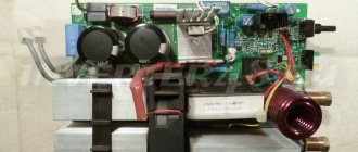
The use of high-frequency converters has made it possible to reduce the weight and size of welding machines. The electronic “filling” makes it possible to regulate and maintain the parameters of the electric arc with high precision and maintain them at the required level. The main elements of inverters are diode bridges, transistors (MOSFET or IGBT) and control boards. They make the design of the devices quite complex, but convenient to use. To maintain high performance characteristics of the devices, electronic control systems are used to monitor the operation of powerful transistors, power supply parameters and output current.
Compact welding inverter Semiconductor devices began to be used in electronic devices back in the 60s of the twentieth century. A little later, a thyristor pulse voltage converter was developed and tested in practice, intended for welding work. In fact, it was the first welding inverter.
Why do inverters break down?
All breakdowns of welding inverters can occur for three reasons:
- Due to violation of welding technology. In this case, the estimated time of continuous operation of the device specified in its passport (PV) is exceeded. As a result, the device overheats and the risk of failure of its transformer or electronic components increases.
- Due to the wrong choice of work location. In this case, moisture or a large amount of construction dust with metal inclusions can get inside the inverter, to which devices of this type are very sensitive (this is the main one of the few weak points of inverters). The result is highly likely to be failure of the electronic boards.
- Due to a broken cooling fan. Its cause, in turn, may be a manufacturing defect or improper operating conditions of the inverter.
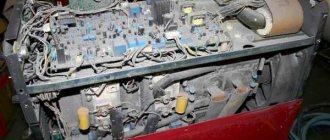
Electronic “filling” of the welding inverter
Main types of breakdowns of welding inverters
There are several most common types of breakdowns of inverter welding machines:
- Spontaneous shutdown of the device. Its cause is most often a breakdown of capacitors, short circuit of turns of transformer coils or wires. The device is saved from permanent failure by a timely triggered protection that turns it off. It should be noted that spontaneous shutdown is not necessarily a consequence of a breakdown. The protection may trigger if the inverter overheats and simply needs timely rest.
- No arc when the device is turned on. In this case, the cables may be damaged or their connection may be unreliable.
- Electrode sticking. There may be several reasons for this: low voltage in the network, unsatisfactory preparation (cleaning) of the surfaces to be welded, the use of a long extension cord (more than 40 m) or a small cross-section (less than 2.5 mm2).
- Unstable arc combustion and increased metal spattering. Most often, the reason for this is the incorrect choice of welding current.
- Increased power consumption when there is no load. This is possible as a result of the short circuit of the turns of the transformer coils. In this case, it needs to be restored, rewinded or replaced.
- Breakage of the welding arc and the impossibility of its re-ignition. The reason may be a short circuit in the wires or a breakdown of the high voltage winding of the transformer.
- Violation of the accuracy of welding current adjustment. This may occur due to deterioration in the mobility of the secondary coils of the transformer due to the accumulation of dust or debris in it, or a malfunction of the adjusting screw.
- Increased noise during operation of the transformer and heating of the latter. There may be several reasons for this situation: failure of the transformer core fastening, loosening of the bolts holding the magnetic core sheets together, or overload of the transformer.
Welding inverter repair
Conclusion
Inverters are rightfully considered reliable and functional welding equipment, but they still have several weak points. One of them can be called their electronic components. They make the devices extremely convenient and efficient, but at the same time vulnerable to water and construction dust. To ensure a long service life, inverter devices must be protected from moisture and dust.
The second weak point of the devices is the cooling fans. If they break down, the inverters will overheat with subsequent possible failure.
Share with your friends:
vistek-weld.ru
Content:
A welding inverter is modern equipment, the use of which in the welding process allows one to achieve very high quality work and provides the welder with the opportunity to work in comfortable conditions. But at the same time, the welding inverter also has a more complex design, compared to previous models of welding equipment, which increases the chance of a malfunction occurring during its operation.
As a rule, all malfunctions of the welding inverter can be divided into two groups:
- malfunctions associated with improper operation of the electronic “stuffing” of the device
- malfunctions associated with incorrect choice of operating mode.
The second type of malfunction occurs most often, therefore, before contacting a specialized workshop or starting to disassemble the device yourself in order to identify a breakdown, you need to check whether all operating mode settings are set correctly, and in addition, you should read the operating instructions for this device again, to determine if you are making any mistakes while working. Most manufacturers, when drawing up instructions, indicate the causes of welding inverter malfunctions that may occur during operation, and also describe how these malfunctions can be eliminated independently.
Causes of breakdowns of welding inverters and options for eliminating them.
There are a number of typical faults that occur when it comes to welding inverters:
- instability of the welding arc and strong spattering of metal;
- welding electrode sticking;
- lack of welding process when the machine is turned on;
- lack of response from the device when it is turned on.
Let us consider in more detail why this or that situation may arise, and what can be done in the event of any malfunction of welding inverters.
- Instability of the welding arc and strong spattering of metal.
This malfunction can occur if you select the wrong current when welding. As a rule, the welding current is selected in accordance with the type and size of the electrode used for welding. But here it is necessary to remember one more important rule: the selected current must correspond to the speed at which welding is carried out. If the welding speed decreases during operation, then the welding current must be reduced.
- Welding electrode sticking.
In fact, there may be several reasons for this type of malfunction. It is quite possible that during welding the voltage in the network suddenly decreased, which led to severe sticking of the welding electrode. It can also “stick” if the inverter is connected to the network with a cable with too small a cross-section. Another reason for this “behavior” of the electrode may be poor contact of the electrode with the surface to be welded due to the fact that the surface has undergone oxidation due to exposure to atmospheric oxygen. In this case, welding must be stopped and the surface of the part must be cleaned of film.
- Lack of welding process when the machine is turned on.
In the vast majority of cases, this behavior of the welding inverter can be explained by the lack of mass on the surface of the part being welded. In addition, it would be useful to check the condition of the welding cable - it may be damaged. This situation occurs quite often if the part being welded is heavy, as a result of which the part falling onto the wire can damage its integrity.
- The device does not respond when turned on.
If nothing happens when you turn on the welding inverter, then the cause of such a malfunction should be sought, in many cases, not in the inverter itself, but in the electrical network to which it is connected. The mains voltage may be too low and therefore the device cannot operate. Another reason that the device does not turn on may be an incorrectly selected circuit breaker installed in the panel. A weak switch can turn off when the inverter is turned on. In addition, turning off the device can lead to a loss of electricity throughout the house.
In addition to the indicated malfunctions, there are also interruptions in the operation of the welding inverter, which are not related to the breakdown of the device, but are a consequence of the fairly high-quality and timely operation of the protection systems with which the inverter is equipped. For example, during prolonged continuous operation, the inverter may turn off spontaneously. This happens if the device overheats and the temperature protection trips. In this case, you should stop the welding process for about 20-30 minutes, allow the device to cool, after which work can be continued.
Common breakdowns
Inverter sparks
One of the most common malfunctions in a budget inverter. Often, under such circumstances, the device sparks but does not cook. That is, the arc is ignited for a split second and then goes out again. There can be many reasons for this breakdown. But first things first.
Start by carefully inspecting the welding cables you use in your welding. Often they are the problem. Even if you do not see any noticeable defects, connect other (preferably new) cables to the holder and ground, and try to strike the arc again. Also check that all connectors are secure.
If the inverter continues to spark, then the problem may lie in the electrolytic capacitors in the inverter. Replace them if you have sufficient skills. If this does not help, then look at the wires on the package. They may be burnt and need to be replaced.
If unsuccessful, it is better to take the device to a service center. Because there may be a dozen reasons for this problem. The service center will give you a full diagnosis and be able to find out the true cause.
The inverter does not cook
The inverter welding machine may be turned on, all indicator lights may be normal, but no welding is taking place. The most common cause of such a breakdown is overheating of the device. We will talk about how to eliminate overheating below.
Also check the condition of the welding cables, they may be damaged or simply need to be replaced. Connect new welding cables and try again to check the operation of the machine.
The inverter is overheating
One of the main reasons why a welding machine welds poorly or does not weld at all. If you cook for more than 10 minutes without a break, the appliance may overheat. Many inverters are equipped with overheat protection, but sometimes it does not work. Then the inverter simply stops working, but remains turned on.
The problem can be solved very simply. Stop welding for half an hour. Leave the inverter to rest. In half an hour it will return to normal and you can continue working.
The inverter does not work, does not turn on
Another one of the most common problems. You plug the device into the outlet, but it shows no signs of life. There may be several reasons. It's usually all about your mains voltage. It may not be enough to turn on the welding machine. If you cook at the dacha, then the probability of low voltage at the output is very high. The problem is solved by purchasing a voltage stabilizer and connecting it to the device.
Another reason is a problem with the network cable with which the device is connected to the outlet. Check the integrity of the cable and plug. You can remove the body of the device and see if everything is in order with the rest of the network cable, hidden from view.
If everything is fine with the cable, but the stabilizer did not help, then the cause of the malfunction is probably in the power supply of the inverter itself. In this case, we recommend contacting a service center. There is a high probability that you will not be able to repair the welding inverter at home without outside help.
Current is not adjustable
You turn the current control, but nothing happens. Most likely, the problem lies in the regulator itself. It is necessary to replace either the regulator or check the reliability of its connection to the wires. Remove the body of the device and check everything carefully. Use a multimeter to diagnose the regulator.
If the regulator is working, but the current is not regulated, then the reason may be a shorted inductor or a malfunction of the secondary transformer. Replace these components or take the device to a specialist. He knows what to do with it.
Electrode sticks to metal
Many modern inverters are equipped with an anti-stick function that prevents the electrode from sticking to the metal. But sometimes this function does not work correctly or does not work at all due to other device failures.
The first reason for the electrode sticking to the metal is an incorrectly selected welding mode. We talked in detail about how to set up the welding mode in this article.
The second reason is the same low voltage of your electrical network. There are inverters that can operate at reduced voltage. But in some places the voltage is so low that even such devices cannot cope with the work. The problem is solved by purchasing a voltage stabilizer.
The third reason is the use of welding extensions. Sometimes the welding cable is simply not long enough to complete the welding job. In this case, you can use a special extension cord. But keep in mind that if its length exceeds 40 meters and its cross-section is less than 2.5 mm2, then there is a high probability of a decrease in voltage during welding. And after this, the electrode sticks to the metal.
The fourth reason is poor preparation of the part before welding. For example, you are welding metal with an oxide film on the surface, but you did not clean the part thoroughly enough before performing the work. As a result, the film formed again and worsened the contact of the electrode with the metal, causing sticking