DC electric motors, now widely used in everyday life and in production, have many advantages, but are characterized by high starting currents. There are several common options for connecting such electric motors.
Thanks to the excellent traction capabilities of DC electric motors, electrical equipment assembled on their basis has become widespread, both in everyday life and in production. Such motors can often be found in modern children's toys, fans, power tools and autonomous industrial electrical installations. They are an integral part of vehicle control and electrification systems. Batteries or rechargeable batteries of different capacities are usually used as a power source.
The DC motor also has many other advantages, including:
- simple speed adjustment;
- possibility of soft start and smooth increase in speed;
- the ability to accelerate to speeds of over three thousand revolutions per minute.
Despite all these advantages, a DC electric motor has a more complex design than an asynchronous AC power unit of 380 or 220 volts, which implies some difficulties in its operation. In addition, there is a danger of significant inrush currents, so there are different ways to connect DC motors, each of which has its own characteristics and nuances. To better understand them, let's take a closer look at the design, operating principle and connection of a DC motor.
DC motor connection diagram
If we try to show the structure of a DC electric motor schematically, we will get an image with two cylinders placed one inside the other. The larger of the cylinders is hollow and motionless and is called a stator or frame. An anchor is placed inside the frame - the smaller of the cylinders, which is movable. In this case, there must be an air space inside between the cylinders and they should not be in close contact. This is necessary because it is in the air gap that the magnetic field is formed.
Direct start of electric motor
A low-power electric motor (up to one kilowatt) is easiest to turn on directly. Like connecting a 380V three-phase motor, this start of a DC electric motor P involves supplying voltage from the power source directly to the working winding. Since there is no natural compensation due to the counteracting electromotive force, the inrush current reaches its maximum value.
If we consider direct connection from a physics point of view, the situation looks like this. Initially, when the motor starts, the current strength has a value determined by the formula: I=U/R, where U is the rated voltage, R is the resistance of the coils. In this case, the current load reaches its maximum value and can be more than twice the nominal value.
Further flow of current initiates the appearance of an electromotive counterforce, which acts as a kind of brake, normalizing the starting load to rated power. The current strength is now calculated using a different formula: I=U-E/R, where E is the counter emf.
In powerful power units, for example, crane motors DK213MD2, the resistance of the rotor windings can reach one Ohm, which provokes the occurrence of a starting current of up to 500 amperes, which is tens of times higher than the permissible value. This can cause thermal sinking of the metal, melting and deformation of wires, damage to contact brushes and rings, and also creates an increased risk of electric shock to operating personnel. Therefore, to turn on electric motors of medium (for example, series D) and high power, it is recommended to use rheostats, special regulators or a deliberately low voltage. Direct launch is contraindicated for them.
DC motor design
Any electric motor consists of two main parts: the frame (stator) and the armature. On the inner surface of the stator there are poles, which are made of thin sheets of electrical steel, insulated from each other using varnish and ending in extensions - tips. These tips are designed to evenly distribute magnetic induction in the air gap. Several excitation windings are located directly at the poles themselves. Moreover, some of the windings are made with a large number of turns of thin wire, while others are designed with a small number of turns of thick wire.
The armature is a gear cylinder that is mounted on a shaft inside the stator and consists of packages of thin sheets of electrical steel insulated from each other. It is worth noting that between each individual package there are special channels designed for ventilation. At the same time, the individual grooves of the armature are connected to each other by conductors made of copper. Also a necessary condition for the manufacture of an armature is the presence of a two-layer winding.
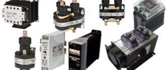
Switching on via starting rheostat
This connection diagram provides for the presence in the starting circuit of the electric motor of an additional device that creates variable resistance. There are several ways to connect it and which device to use. But the goal here is the same - to ensure a reduction in the current load at the start until the shaft reaches the optimal rotation speed. In the process of stabilizing the current strength, the resistance of the rheostat should change from maximum to minimum. The calculation is made using the formula: I=U/R+R(rheostat).
Many people are probably familiar with similar experiments from school physics classes, when the resistance was changed manually by moving the rheostat slider. However, in production this method is ineffective and poorly coordinated with current values, so it is rarely used. The connection option with current or electromotive force control in the field windings is more often used. Installation to a time relay is also common, where individual stages are independently controlled by means of a time delay.
A distinctive feature of AC power units (as opposed to those designed for 3ph alternating current or 220 volts) is the presence of field windings. The connection methods listed above are applicable to electric motors of all types of excitation:
- independent;
- parallel;
- consistent;
- mixed.
But there are some nuances here. Independent excitation motors cannot be started at idle or at low loads, otherwise the unit will be damaged by a sharply increased rotation speed. When connected in parallel, much less current passes through the field winding than through the rotor part, so the motor has rigid characteristics useful for machine tools or fans. If the rotor and field winding are connected in series, then the current of the same magnitude will flow through them. This power unit, common in modern electric vehicles, has good starting properties, but is also afraid of starting at idle.
Operating principle of a DC motor
The operating principle of any modern DC electric motor is based on the principle of magnetic induction, as well as the “Left Hand Rule”. If current is passed through the upper part of the armature winding in one direction, and through the lower part in the other, it will begin to rotate. This is due to the fact that, according to the left-hand rule, the conductors that are laid directly in the grooves of the armature will be pushed out of the magnetic field that is created by the frame.
Thus, the upper part will be pushed to the left, and the lower part to the right, which will lead to rotation of the armature itself, since all the energy from the conductors will be transferred to it. However, at the moment when the conductors rotate and parts of the armature change locations, its rotation will stop. To prevent this from happening, the electric motor uses a commutator designed to switch the armature winding.
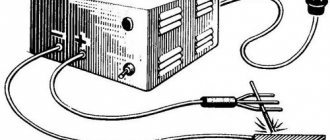
Connection via Arduino chip
Low power engines can also be started using special functional platforms. A common method now is to connect a DC motor to Arduino. It is better not to connect directly via Arduino, since there is a high probability of damaging the chip. It is recommended to use an H-bridge or transistors. This technology for introducing electric motors into functional circuits provides many opportunities for controlling and driving the working parts of electric machines, modern vehicles and robotic mechanisms. You can control not only the speed of the motor, but also the direction of its movement.
Direct connection to the platform output ports will not only cause them to burn out, but will also reduce the motor control functionality to a minimum. Each such port can supply a current of about twenty milliamps, and for normal operation even the most compact electric motor requires many times more. Therefore, the motor must be connected to the Arduino in series through a current regulator.
When choosing a suitable motor for connection to a microcontroller, you should pay attention to the following characteristics:
- current consumption required for normal operation of the equipment;
- nominal voltage (the most common for such systems is 12 volts);
- rotational moment - the greater it is, the more powerful the unit;
- speed of rotation of the electric motor shaft;
- weight and dimensions - preference is now given to miniature models.
The easiest way is to serially connect a standard brushed DC motor to Arduino, designed for a current of up to 5A and an operating voltage of about 9V. A transistor system is often used for this. But it only allows you to control the speed of revolutions. Connecting to a microcontroller via an H-bridge also makes it possible to adjust the direction of rotation.
Classification
All three-phase electric motors can be divided into two groups:
Synchronous. They rotate at the speed of a constant magnetic field. To increase power, the rotor is made according to the principle of a transformer - it has windings and a core. Voltage is supplied through carbon brushes to the commutator rings (contacts) mounted on the shaft, and only then to the rotor coils.
Asynchronous, with a squirrel-cage rotor. The rotational impulse comes from the excitation of the stator coils. The short-circuited turns are made in the form of a squirrel wheel. The rotor rotates at a speed lower than the electromagnetic field of the stator. Hence its name.
Application of magnetic contactor
To organize a soft start, it is necessary to introduce a special switching device - a starter - into the power circuit. This is one of the connector options that can be supplemented with optional elements, for example, a thermal relay. A huge advantage of this scheme is the possibility of organizing not only the start-up of electricity. the engine, but also stopping it, reversing it, as well as protecting connections from damage by excess currents. In addition, the core or coil can have a voltage rating of 380 or 220V, which allows you to connect the motor to a power and household network.
Classic electrical circuits for connecting motors through a starter can be divided into two types:
- Irreversible. Connection of the unit and the network without the need/possibility of organizing its reverse movement. In this case, it is possible to integrate both into a power and household (220V) network,
Non-reversible connection diagram
- Reversible. An electrical circuit that combines two starters (unit) with a circuit breaker. It is also possible to change the direction of rotation of the rotor assembly for power and household (220V) networks.
Reversible connection diagram
As you can judge from the illustrations, the differences between the “network” options lie in the connection points of the contactor terminals:
- for 380 volts the contacts are closed on 2 of 3 phases,
- for 220 volts, one of the contacts is connected to the extreme phase, and the second to zero.
Thermal relay
In addition, in all four options there is an element designated as “P”. This is nothing more than a thermal relay. It is connected in series with the contactor coil and serves to protect the motor from excessive current loads.
According to the principle of operation, the thermal relay is a key, that is, when critical current values for the operation of the unit and contactor are reached, a temporary break in the power supply occurs. Some types of thermal relays or “thermal relays” are used for DC circuits or specific modes (delayed start-up, phase failure, etc.).
Constant activation of the magnetic starter leads to mechanical wear of the contacts, which a thyristor or contactless circuit does not have. The circuit is broken not mechanically (dividing the contact group), but electronically - due to diode bridges.
Pros - cons
The technical characteristics of asynchronous electric motors with a squirrel-cage rotor are so superior to those of synchronous ones that most drives are made on their basis.
The advantages of such devices are:
- Reliability, simplicity of design, durability;
- No difficulties in repair and maintenance;
- By switching 2 phases, you can make the shaft rotate in the opposite direction;
- Application as a generator.
There are also disadvantages or disadvantages:
- If the phasing is incorrect, the shaft can rotate in the wrong direction and jam other mechanics (gears);
- Inrush current up to five times the rated current;
- Acceleration and braking speed. Some devices with high inertia require higher power motors.
- If a phase is broken, the motor may burn out if the voltage supply is not turned off in a timely manner.
Start by changing the supply voltage
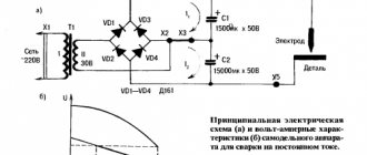
One of the options for reducing the current load when starting an electric motor is to reduce the supply rating using a constant voltage generator or a controlled rectifier.
From a physical point of view, installing a rheostat provides the same effect, but as the power of the electric motor increases, the constant current load also increases, and losses on the rheostats increase significantly. Therefore, DC voltage reduction is performed by a separate microcircuit-based device, an example of which is shown in the figure below:
Rice. 5. Starting circuit with changing supply voltage
How to choose the right capacitors
Its switching diagram is assembled in such a way that in the first position all contacts are open, in the second two are closed: power and starting capacitors, and in the third - only power. The whole difference is that in bifilar single-phase motors the starting winding works only until the motor accelerates. Accordingly, the cross-section of the working winding wire is larger than that of the starting winding.
Now one bundle of wires, for example, with the number 1, will be the beginning, and the other will be the end. Active resistors, inductors and capacitors can be used for this. They even have labels that indicate that you can connect to both a three-phase network and a single-phase network. Using a tester, the wires are pinged to find the coils.
The working one has the lowest resistance, the average value is the starting winding, and the highest value is the common output; the resistance of two windings connected in series is measured.
But how to do it right? With an asymmetrical stator magnetic circuit A feature of motors with this design is the asymmetrical shape of the core, which is why pronounced poles appear.
The beginnings and ends of these windings are brought out into the BRNO box, the switching or distribution block for the beginning of the windings, and, as a rule, the engine passport is inserted into it: If the motor has two voltages, then there will be six terminals in the BRNO. To do this you will need two voltmeters.
Let's look at the electric motor connection diagrams for both cases: Connection diagrams for the electric motor through a capacitor. How to connect a single-phase asynchronous motor with a starting winding to the network
We recommend: Phase zero measurement method
Connecting a three-phase 380 volt motor
If we apply alternating current to the coil, we get an alternating field.
Such motors are produced only as single-phase ones; they are often installed in household appliances, as they allow one to obtain a large number of revolutions at the start and after acceleration.
It is impossible to know accurately the power factor and power of the motor, and therefore the current strength.
The advantages of an inverter for connecting unconverted three-phase electric machines to volts; obtaining full power and torque of the electric machine without losses; energy saving; smooth start and speed control. For automatic starting, a second starting winding is used, as in a two-phase electric motor.
Read more: laying cables in the ground snip
Connection diagram for a 220 Volt commutator motor
By the way, the washing machine motor is produced through a capacitor. The turns of a short-circuited winding lead to significant energy losses, which is the main disadvantage of the circuit, but it is relatively often used in air conditioning and heating devices with a fan.
In other words, there must be two switches: one general, the other a starting one, which, after being released, would turn itself off. Therefore, it is important to release the start button in a timely manner. It is connected to the main electrical network through capacitance or inductance. Using capacitors for DC voltage in AC networks is highly discouraged due to the fact that capacitors explode.
And in many cases, electrical equipment is driven by three-phase motors. Always carefully read what is written on the tag! Now the engine that was connected for can be connected to the volt network.
We have two mutually perpendicular vectors, varying according to a sinusoidal law with a phase shift of 90 degrees. If during operation the motor overheats, it means that the capacity of the device is greater than required. Let's say we calculated a capacitance of 40 µF. connecting a 380 to 220 volt motor
Classic connection options
Most emails Motors for modern electric drives operate from an alternating three-phase line (each of the three phases is supplied by a separate conductor). Accordingly, the terminal box contains the terminals (input and output) of three windings. They can be connected to each other and to the network using two classic schemes: “star” and “triangle”.
Star and Delta connection diagram
For the first, a characteristic feature is the closure of the end terminals of each coil to one point (in practice, this is one neutral). Meanwhile, the mains voltage is supplied to the input pins. This scheme is characterized by a softer ride, but unfortunately, it does not allow you to develop full power.
The second option with a triangle is characterized by a serial connection of the terminals of the windings: the end of the first is connected to the beginning of the second, etc. This starting option guarantees achievement of the rated power, but during switching on, large currents may arise that can thermally damage the winding terminals.
If you remove the terminal box cover, both connection options will look like this:
Electronics for everyone
After the previous post about the gear motor, I received several questions about regulating a DC motor. So it's time to write another post 
The direct current motor (DC motor) is one of the most familiar and understandable electric motors; it is studied even in school, in physics. It is used almost everywhere where a small-sized motor is needed, and is also in no hurry to lose its position even where power is measured in tens of kilowatts. Let's talk about him. ▌ Design and basic principle
I won’t go into too much detail here, I’ll show you a picture from Wikipedia and indicate a number of main components. Everything else you already know and have touched with your own hands.
1. The stator consists of a magnetic field source. This is not always a permanent magnet; moreover, a permanent magnet is the exception rather than the rule. Usually this is the excitation winding. At least on anything larger than a fist.
2. The armature consists of an armature winding and a collector unit.
Everything works very, very simply. The armature winding is repelled from the magnetic field of the stator by the Ampere force and makes half a revolution, trying to bring this force to zero and would have brought it out if not for the collector, which cleverly breaks off everyone, switches the polarity of the coil and the force again becomes maximum. And so on in a circle. Those. the collector serves as a mechanical voltage inverter in the armature. Remember this moment, it will be useful to us later
Usually in small motors there are only two poles of the field winding (one pair) and a three-prong armature. Three teeth is the minimum for starting from any position, but the more teeth, the more efficiently the winding is used, the lower the currents and the smoother the torque, since the force is a projection onto the angle, and the active section of the winding rotates to a smaller angle
▌Processes occurring in the engine
I think many of you who have dabbled with engines may have noticed that they have a pronounced starting current, when the motor at the start can jerk the ammeter needle, for example, to an ampere, and after acceleration the current drops to some 200 mA.
Why is this happening? This is how back emf works. When the engine is stopped, the current that can pass through it depends only on two parameters - the supply voltage and the resistance of the armature winding. So it’s easy to find out the maximum current that the engine can develop and for which the circuit should be calculated. It is enough to measure the resistance of the motor winding and divide the supply voltage by this value. Simply by Ohm's law. This will be the maximum starting current.
But as it accelerates, a funny thing begins: the armature winding moves across the magnetic field of the stator and an EMF is induced in it, like in a generator, but it is directed opposite to the one that rotates the engine. And as a result, the current through the armature decreases sharply, the more, the higher the speed.
And if the engine is further tightened along the way, then the back emf will be higher than the supply and the engine will begin to pump energy into the system, becoming a generator.
▌A few formulas
I won’t burden anyone with conclusions; you’ll find them yourself if you want. To make it less profane, I recommend finding a textbook on electric drives for secondary schools and an older year of publication. It’s from the 50s-60s. There are vintage pictures and painted for yesterday’s graduate of a rural seven-year school. Lots of letters and no sinkers, everything is clear and to the point.
The most important formula for a brushed DC motor is:
U = E + I*Rya
- U - voltage supplied to the armature
- Rya is the resistance of the anchor chain. Usually, only the resistance of the winding is considered as this symbol, although you can hang a resistor on the outside and it will be added to it. Then they write it as (Rа+Rд)
- Iya is the current in the armature circuit. The same one that is measured with an ammeter when trying to measure engine consumption
- E is the back emf or emf of the generator, in generator mode. It depends on the engine design, speed and is described by this simple formula
E = Ce * F * n
- Ce is one of the design constants. They depend on the design of the motor, the number of poles, the number of turns, and the thickness of the gaps between the armature and the stator. We don’t really need it; if desired, it can be calculated experimentally. The main thing is that it is constant and does not affect the shape of the curves
- F is the excitation flux. Those. stator magnetic field strength. In small motors, where it is set by a permanent magnet, this is also a constant. But sometimes a separate winding is brought out for excitation and then we can change it.
- n - armature revolutions.
Well, the dependence of torque on current and flow:
M = cm * Iа * F
Cm is a constructive constant.
Here it is worth noting that the dependence of torque on current is completely direct. Those. Simply by measuring the current, with a constant excitation flux, we can accurately determine the magnitude of the torque. This may be important, for example, in order not to break the drive, when the engine can develop such a force that it can easily break what it rotates there. Especially with a gearbox.
Well, it follows from this that the torque of a DC machine depends only on the ability of the source to supply it with current. So the ideal indestructible superconducting engine will tie you in knots, even if it’s as small as a nail. Just supply energy.
Now let’s mix it all together and get the dependence of revolutions on torque - a mechanical characteristic of the engine.
If you build it, it will be something like this:
n0 is the ideal idle speed of a spherical engine in a vacuum. Those. when our engine is finally freezing, the torque is zero. The current consumption is also, naturally, zero. Because back emf is equal to voltage. Purely theoretical option. And the second point is constructed with some moment on the shaft. It turns out there is a direct relationship between speed and torque. And the slope of the characteristic is determined by the resistance of the armature chain. If there are no additional resistors there, then this is called a natural characteristic.
Ideal idle speed depends on voltage and flow. Nothing else. And if the flux is constant (permanent magnet), then only from voltage. By reducing the voltage, our entire characteristic shifts down in parallel. Reduced the voltage by half - the speed dropped by half.
If it is possible to change the excitation flow, then you can raise the speed above the nominal one. Here the relationship is reversed. We weaken the flow - the engine accelerates, but either the torque drops, or it needs to consume more current.
Another engine with excitation removed may go into disarray. I remember I took a long course on electric drive, who knows how long after the session. I had to break it, yeah. Well, I sat in the laboratory, waiting for the teacher. And there were some dunces, a course lower, who made a lab. They turned the engine idle, and the excitation was attached to the stand on snot and flew off the terminal. The engine went haywire. In our laboratory at EPA SUSU, everything was serious, the machines were serious, ten kilowatts and about a hundred or so kg each. Everything is at a harsh voltage of 380 volts. In general, when this fool roared like a monster and began to tear itself from its mounts, all I had time to shout was to get the hell out of the car, turn it to hell. Before we had time, the engine was torn from its mounts, the windings flew out of the grooves and the engine suffered damage. Okay, no one was hurt. However, the drive labs were still entertainment. We had fires and explosions there. There I acquired remarkable skills to fix anything, with anything, in a short time. On average, everyone managed to completely kill the stand once, and the lab often began with repairing the soldering iron, which was used to repair the oscilloscope, with the help of which the dead stand was reanimated.
By adding resistors to the armature circuit we can increase the slope, i.e. The more we load, the more the speed drops.
The method is bad because the resistors in the armature circuit must be rated for the motor current, i.e. be powerful and will heat up in vain. Well, the moment drops sharply, which is bad.
There are also motors with sequential rather than independent excitation. This is when the stator winding is connected in series with the armature. Not every motor can be turned on this way; the field winding must withstand the armature current. But they have one interesting property. When starting, a large starting current occurs and this starting current is also the excitation current, providing a huge starting torque. The mechanical characteristic resembles a hyperbola with a maximum in the region of zero revolutions.
And then, as you accelerate, the torque drops, and the speed, on the contrary, increases. And if the load is removed from the shaft, the engine immediately goes into overdrive. Such engines are mainly installed on a draft drive. At least they did before, before the development of power electronics. This crap explodes from its place so much that all the street slayers nervously light up.
▌DC motor operating modes
The direction of rotation of the motor depends on the direction of the armature current or the direction of the excitation flow. So if you take a commutator motor and connect the excitation winding parallel to the armature, then it will rotate perfectly on alternating current (universal motors, they are often installed in kitchen appliances). Because the current will simultaneously change in both the armature and the excitation. The moment will indeed be pulsating, but these are minor things. And to reverse it, you will need to change the polarity of the armature or excitation.
If we draw a mechanical characteristic in four quadrants, we will have something similar to this:
For example, characteristic 1 in section I, our car works like an engine. The load increases and at a certain moment the engine stops and begins to rotate in the opposite direction, i.e. the load reverses it. This is a braking mode, anti-inhibition. The mode is very difficult, the engine heats up simply brutally, but it is very effective for braking. If the moment on the shaft changes direction and starts to rotate towards the engine, then the motor will immediately go into generation (section IV).
Characteristic 2 is the same, only with reverse polarity of the motor supply voltage.
And characteristic 3 is dynamic braking. It's rheostat. Those. when we take and simply short-circuit our motor to a resistor or to itself. You can check it yourself, take any motor and spin it, and then short-circuit its armature and spin it again. There will be a noticeable force on the shaft, the greater the quality of the engine.
By the way, motor drivers like the L293 or L297 have the ability to turn on rheostatic braking by turning both keys up or down. In this case, the armature shorts through the driver to the ground or power bus.
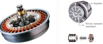
▌Brushless DC Motors
The collector engine is very good. It's damn easy and flexible to adjust. You can increase the speed, lower it, the mechanical characteristics are tough, it holds the torque with a bang. The dependence is direct. Well, it's a fairy tale, not a motor. If it weren't for one spoonful of shit in all this deliciousness - a collector.
This is a complex, expensive and very unreliable unit. It sparks, creates interference, and becomes clogged with conductive dust from the brushes. And under heavy load it can blaze, forming a circular fire, and then that’s it, the engine is screwed. It will short-circuit everything tightly.
But what is a collector anyway? Why is he needed? Above I said that the collector is a mechanical inverter. Its task is to switch the armature voltage back and forth, exposing the winding to the flow.
But it’s already the 21st century and cheap and powerful semiconductors are now at every turn. So why do we need a mechanical inverter if we can make it electronic? That's right, there's no need! So we take and replace the collector with power switches, and also add rotor position sensors so that we know at what moment to switch the windings.
And for greater convenience, we turn the engine inside out - it’s much easier to rotate a magnet or a simple excitation winding than an armature with all this junk on board. The rotor here is either a powerful permanent magnet or a winding powered by slip rings. Which, although it looks like a collector, is far more reliable than it.
And what do we get? Right! Brushless DC motor aka BLDC. All the same cute and convenient characteristics of the DPT, but without this nasty collector. And do not confuse BLDC with synchronous motors. These are completely different machines and have different principles of operation and control, although structurally they are VERY similar and the same synchronizer can easily work as a BLDC, adding only sensors and a control system. But that's a completely different story.
Operation of devices with a specific moving part
The usual version of the rotor assembly of a three-phase asynchronous electric motor is a short-circuited “squirrel cage” type, which is assembled from steel plates. When there is a need to reduce the rating of starting currents with the ability to regulate the rotation speed, then a wound rotor is used. Its characteristic feature is two groups of conclusions:
- Stator. Classic terminal block to which mains voltage is supplied (380 or 220V),
- Rotary. Additional terminal block for the terminals of the wound rotor windings, to which the contacts of the rheostat (resistance block) are connected.
The latter is necessary for a smooth start with gradual switching on/off of individual resistances in the wound rotor winding circuit.