- home
- About company
- Articles
- Mechanical restoration
- Features of the use of turning and milling processing
Modern production (machine, machine tool, etc.) involves the use of a large number of parts and fasteners. Component elements are manufactured using machine turning and milling processing. The required shape and dimensions are given to the blank using special equipment - multifunctional machines that support numerical software. Their use ensures ideal processing quality and makes it possible to achieve maximum precision.
What milling devices are there?
When producing products with a small volume of milling work, you should not buy a separate unit. Small flat elements, recesses and grooves can be made using a special device on a lathe.
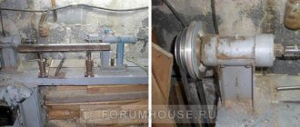
An industrial model of such equipment is a universal lathe with a milling head. The device is installed on the headstock or on the rear support and is activated from a common control panel.
For home equipment, especially tabletop lathes, the milling unit is produced by industrial enterprises, and craftsmen do it themselves. Using devices on a part installed in turning equipment, the following is performed:
- removing bald spots;
- edge milling;
- selection of grooves;
- grinding a flat surface.
If there is a dividing head, polyhedra are made and splines are milled.
Reference! Using a milling device, holes are drilled along the ends of flat parts and the surface is ground.
Milling work on a lathe - Community "Garage Equipment and Tools" on DRIVE2
Sometimes, due to work, you have to make non-standard fasteners. Any fastener has something to tighten it with. Bolts have heads, nuts have faces, etc. A bolt with a round head made from round timber is difficult to tighten. You need to make edges (at least two) or a slot. The work doesn’t seem to be difficult, but one way or another you have to turn to a milling cutter, who doesn’t always have time for this. And because of one or two bolts, it’s simply too lazy to adjust the milling machine. I want to share how I got out of this situation. I repeat, you can make a square or hexagon by hand, it’s not a tricky thing. But it’s better to do it on the machine, carefully. I developed and manufactured a small dividing head for these purposes. For 4 and 6 divisions. The second, two years later, I made for a friend, at his request, for 12 divisions. Very helpful. You can also cut a slot with a disc cutter for a screwdriver. Drilling/milling side holes. Keyway on small (up to 20mm) shafts. Castle, hub nuts and bolts. Making valve handles with blades, like on household gas stoves. In general, the device is multifunctional. It can be clamped into the tool holder both along and across the caliper. Maybe someone will find this idea useful.)
And ideally, maybe someone would organize the release. I think it would be in demand. Eh, people?
=========================================================
Examples of other works.
===================================================== =======Rear view.
Full size
At the ends of the housing there are two bearings 1000906 (30x47x9). It is fixed with a spring-loaded cone stopper.
There are thoughts about attaching a boring head to it to make ball pins. You can put something under the lock on the dividing head and the cartridge rotates freely.
There are still not enough small vises for the lathe. Like Pavel. Also still in the plans. Still don't get around to it.)))
www.drive2.ru
Types and purpose
Depending on the design and technological application, milling devices are conventionally divided into groups:
- head with separate drive;
- console;
- device for fixing the part.
The milling head is installed on the caliper body from the rear and moves with it in the longitudinal and transverse direction. The vertical stroke is carried out along the guides of the rack of the device itself. The head has its own electric drive, gearbox and controls.
The design of the console is much simpler. The electric drive is used only to rotate the spindle. The rotation speed of the tool can be adjusted only by rearranging pulleys with different diameters. The transmission is belt driven, directly from the motor shaft to the spindle. The set-top box is powered from the equipment network.
Important!
On desktop models of lathes, the milling attachment can be connected directly to a 220 V household network.
A simple mechanical device - a device for milling - allows milling to be done manually. It is installed instead of a tool holder. Vertical guides are cut out on the stand to move the spindle along the Z axis. The part is attached to it and moves relative to the tool rotating in the spindle along the X and Y axes. Vertical displacement of the workpiece is carried out manually.
According to planned economic indicators
Milling processing is used both in small- and medium-scale production (universal milling, console, table-top milling machines), and in serial and large-scale production (turning and milling machines with a CNC module, machining centers). The purchase of high-precision, productive machines with numerical control requires significant financial investments and is justified when production areas are at maximum load.
Milling and grinding accessories
The device is installed in place of the tool holder and moves together with the support and cross slide. On the frame of the device for milling and grinding, a spindle is attached for the tool:
- end mills;
- cylindrical;
- grinding discs;
- conical abrasive wheels.
The device for milling and grinding has its own electric motor connected to the spindle head shaft by a belt drive. Electricity consumption comes from the machine system.
In terms of dimensional accuracy and quality of the resulting surfaces
For pre-processing of the workpiece, rough milling . It is characterized by higher cutting power and depth, and the resulting surface roughness is Ra 6.3...20. Requires equipment of great rigidity and power. When rotating at relatively low speeds, a cutter with brazed or replaceable inserts removes a large thickness of metal.
Finish milling gives more accurate dimensions (6-7) and higher surface finish - Ra 1.25...1.6. The metal layer removed during finishing milling operations is minimal, and the cutting speed is high.
Both finishing and rough milling are operations performed on the same or different machines. Semi-finishing is a combination of two types of finishing, usually with different tools.
The accuracy of the result of all types of milling work depends not only on the processing modes, but also on the parameters and technical characteristics of the milling machine itself (normal precision machines and precision milling machines), on the tool used and on the correct positioning and movement of the part.
Additional details
The use of milling fixtures on a lathe is impossible without the use of additional parts. To mount the unit on the caliper body, you have to make holes and secure the base of the device with bolts.
Additional supports - rests, will reduce the deflection of a long shaft during processing. The center holds a long piece. Collets are necessary for securing cutters in the lathe chuck and fixture spindle. They rigidly fix the tool shank, center it and increase processing accuracy.
The use of a machine rotary vice increases the angle of rotation of the part without reinstallation, increasing the capabilities of the equipment. When working according to the template, a copy sleeve or bearing is installed. It accurately guides the tool along a given path.
Milling work on a lathe — Community “Garage Equipment and Tools” on DRIVE2
Sometimes, due to work, you have to make non-standard fasteners. Any fastener has something to tighten it with. Bolts have heads, nuts have faces, etc. A bolt with a round head made from round timber is difficult to tighten. You need to make edges (at least two) or a slot. The work doesn’t seem to be difficult, but one way or another you have to turn to a milling cutter, who doesn’t always have time for this. And because of one or two bolts, it’s simply too lazy to adjust the milling machine. I want to share how I got out of this situation. I repeat, you can make a square or hexagon by hand, it’s not a tricky thing. But it’s better to do it on the machine, carefully. I developed and manufactured a small dividing head for these purposes. For 4 and 6 divisions. The second, two years later, I made for a friend, at his request, for 12 divisions. Very helpful. You can also cut a slot with a disc cutter for a screwdriver. Drilling/milling side holes. Keyway on small (up to 20mm) shafts. Castle, hub nuts and bolts. Making valve handles with blades, like on household gas stoves. In general, the device is multifunctional. It can be clamped into the tool holder both along and across the caliper. Maybe someone will find this idea useful.)
And ideally, maybe someone would organize the release. I think it would be in demand. Eh, people?
=========================================================
Examples of other works.
===================================================== =======Rear view.
Zoom
At the ends of the housing there are two bearings 1000906 (30x47x9). It is fixed with a spring-loaded cone stopper.
There are thoughts about attaching a boring head to it to make ball pins. You can put something under the lock on the dividing head and the cartridge rotates freely.
There are still not enough small vises for the lathe. Like Pavel. Also still in the plans. Still don't get around to it.)))
www.drive2.com
Tips and tricks
When choosing a device for a lathe, you should decide on the volume and type of work performed, and their accuracy. Then select the appropriate model according to the size of the equipment.
To produce single parts for repairing cars and home appliances, a simple device that fixes the part and moves it relative to the rotating chuck with the tool is suitable.
For a private workshop engaged in the manufacture of parts and simple products, it is worth buying a milling head and making complex parts with high productivity and accuracy.
When the workload is low, a milling device can replace a machine. At the same time, it does not require space for placing equipment, and saves time on reinstalling the workpiece from one operation to another.
Electronically controlled equipment
Digital technologies have penetrated into all spheres of life of modern people. Processing equipment was no exception. With the advent of machines that support electronic program control, the production process has become much simpler, the accuracy and efficiency of processing has increased.
Now all the machines installed in the machine shop are controlled by one master, who sets the program for the movement of working units, selects the operating parameters of the equipment (processing depth, speed, etc.). The computer that controls the operation of the machines creates a program based on the data entered by the master. Based on the compiled program, the workpieces are processed.
Using such equipment, you can process workpieces made from any material (metal alloys, polymers, wood, plexiglass, etc.), thereby obtaining parts of the desired configuration and size. It can work with a huge number of tools. Strict computer control and the absence of human factors guarantee high precision in product manufacturing.
What materials do we process?
Over 30 years, significant production experience has been accumulated. Most materials can be processed using blades. Some are better, others are worse. The main thing is to choose the right tool, modes, coolant. We process according to customer drawings:
- steel (structural, stainless, hardened)
- light alloys (aluminium, bronze, brass)
- difficult-to-cut materials (titanium, pure copper, nickel type Kovar 29NK)
- plastics (polyamide, fluoroplastic, plexiglass, ZEDEX, textolite)
What products do we produce?
The technology allows us to produce any parts:
- cover surfaces;
- strips, levers, brackets of different sizes and configurations;
- radiators for electronic devices;
- steel bodies and their elements;
- parts for machine, aircraft and instrument making.
The range of work is not limited to cutting. Heat treatment, grinding and coating of the part with protective compounds are carried out.
Order stages:
For a preliminary calculation, send technical specifications and drawings by e-mail. The period of work to order depends on the volume of the batch and the complexity of the milling. A minor delay may be caused by suppliers not having the required material, but this is an exception to the rule and rarely occurs.
Why do they contact us?
- Great experience. For more than 14 years we have been fulfilling orders of various sizes, including for large oil production and mechanical engineering enterprises.
- Acceptable prices. A system of discounts is provided for regular and wholesale customers.
- Developed logistics. We quickly place your order and arrange delivery throughout the capital and regions of Russia.
- Fulfilling urgent orders. The deadlines are specified in the official agreement, for failure to which we bear financial responsibility.
- Modern equipment. The use of CNC machines guarantees the speed of execution of large batches of orders and quality control at all stages of work.
The exact price of turning services and metal milling work is calculated individually. You can agree on all the details with our manager by phone. The cost is fixed in the contract and does not change during the process. Minimum order - from 50,000 rubles.
Milling processing
- Home /
- Mechanical restoration /
- Milling processing
Cylindrical and face milling, depending on the direction of rotation of the cutter and the direction of feed of the workpiece, can be carried out in two ways:
1) against feed (counter), when the direction of feed is opposite to the direction of rotation of the cutter;
2) by feed (upstream), when the directions of feed and rotation of the cutter coincide.
When milling against feed, the load on the cutter tooth increases from zero to maximum, while the force acting on the workpiece tends to tear it away from the table, which leads to vibrations and an increase in the roughness of the machined surface. The advantage of counterfeed milling is that the cutter teeth work “from under the crust”, i.e. the cutter approaches the hard surface layer from below and tears off the chips. The disadvantage is the presence of initial sliding of the tooth along the hardened surface formed by the previous tooth, which causes increased wear of the cutter.
When milling by feed, the cutter tooth immediately begins to cut a layer of maximum thickness and is subjected to maximum load. This eliminates initial tooth slippage, reduces wear on the cutter and reduces the roughness of the machined surface. The force acting on the workpiece presses it against the machine table, which reduces vibration.
Schemes for processing workpieces on horizontal and vertical milling machines (Fig. 2)
The movements involved in the formation of surfaces during the cutting process are indicated by arrows in the diagrams.
Horizontal planes are milled on horizontal milling machines with cylindrical cutters (Fig. 2, a) and on vertical milling machines with end mills (Fig. 2, b). It is advisable to use cylindrical cutters to process horizontal planes up to 120 mm wide. In most cases, it is more convenient to process planes with end mills due to the greater rigidity of their attachment in the spindle and smoother operation, since the number of simultaneously working teeth of an end mill is greater than the number of teeth of a cylindrical cutter.
Vertical planes are milled on horizontal milling machines with end mills (Fig. 2, c) and end milling heads, and on vertical milling machines with end mills (Fig. 2, d).
Inclined planes and bevels are milled with face (Fig. 2, d) and end mills on vertical milling machines, in which the milling head with spindle rotates in a vertical plane. The bevels are milled on a horizontal milling machine with a single-angle cutter (Fig. 2, e).
Combined surfaces are milled with a set of cutters (Fig. 2, g) on horizontal milling machines. The accuracy of the relative position of the machined surfaces depends on the rigidity of the cutter attachment along the length of the mandrel. For this purpose, additional supports (suspensions) are used, and the use of cutters that are disproportionate in diameter is avoided (the recommended ratio of cutter diameter is no more than 1.5).
Shoulders and rectangular grooves are milled with end (Fig. 2, h) and disk (Fig. 2, i) cutters on vertical and horizontal milling machines. It is more advisable to mill shoulders and grooves with disk cutters, since they have a larger number of teeth and allow working with high cutting speeds.
Shaped grooves are milled with a shaped disk cutter (Fig. 2, j), corner grooves - with single-angle and double-angle (Fig. 2, k) cutters on horizontal milling machines.
The wedge groove is milled on a vertical milling machine in two passes: a rectangular groove with an end mill, then the bevels of the groove with a single-angle end mill (Fig. 2, m).
T-shaped grooves (Fig. 2, n), which are widely used in mechanical engineering as machine grooves, for example on tables of milling machines, are usually milled in two passes: first, a rectangular profile groove with an end mill, then the lower part of the groove with a T-shaped cutter grooves
Keyways are milled using end or keyway (Fig. 2, o) cutters on vertical milling machines. The accuracy of obtaining a keyway is an important condition when milling, since the nature of the fit of the parts mating to the shaft on the key depends on it.
Shaped surfaces of an open contour with a curved generatrix and a straight guide are milled on horizontal and vertical milling machines with shaped cutters of the appropriate profile (Fig. 2, p). The use of shaped cutters is effective when processing narrow and long shaped surfaces. Wide profiles are processed with a set of shaped cutters.
- Hole Machining Methods
- Rental
How the price is formed
The price of services depends on many variables. It is calculated individually taking into account:
- the customer has an already developed program for the CNC machine;
- availability of a finished drawing of the product, a three-dimensional model, a developed prototype;
- volume of the goods batch;
- features of the part, complexity of the production process;
- urgency of the order.
You can order at the Metallocenter PP with maximum benefit by becoming our regular customer, as well as placing large orders. A flexible system of discounts is provided for regular customers. The terms of cooperation can be discussed individually. To do this, just contact the manager of the enterprise.
When is turning used?
If you need a batch of metal parts or custom-sized products, we are ready to help. We provide prompt services in Moscow and throughout Russia in the event that the full functioning of your production is stopped due to the breakdown of spare parts. The execution time may be affected by the choice of material - steel, stainless steel, aluminum, bronze, copper, etc. Upon completion of turning work, you receive a finished product made to order, that is, corresponding to the pre-approved dimensions, shape, surface roughness and relative position accuracy.
