Technological processing processes
TO
category:
Turning
Technological processing processes
Next: Installing cutters
A technological process is a part of the production process that contains targeted actions to change and determine the state of the workpiece. The technological process must indicate the processing sequence, workpiece dimensions L3 and Dz, processing allowances Ai and Dg (Fig. 141, a), installation and measuring bases, methods of fastening the workpiece, type of fixtures, need for cutting tools (Fig. 14.1, d , e, f), auxiliary (Fig. 141, b, c) and measuring (Fig. 141, g, h) tools.
A technological operation is a completed part of the technological process of processing one or more parts, which is performed at one workplace. The elements of a technological operation are installation and transition. The installation is the part of the technological operation performed while the workpieces being processed remain unchanged. The operation can be performed in one or more installations.
The technological process of manufacturing a part is shown step by step in Fig. 142. Installation (Fig. 143, a) and reinstallation of the workpiece is associated with its unfastening, reinstallation (Fig. 143, b) and new fastening.
A transition is a completed part of a technological operation performed on one of the surfaces of the workpiece using the same cutting tool at a set cutting mode.
Rice. 138. Gauge gauges for controlling shaft diameter
Rice. 139. Methods of measuring snob gauges (a), test gauges (b,c) and templates (d,e) of outer diameters
In Fig. Figure 144 shows how a part can be machined from start to finish in two setups. First, the worker clarifies the drawing of the part (Fig. 144, a), then determines the allowances for processing (Fig. 144.6). During the first installation (Fig. 144, c), the workpiece is completely processed on one side and cut off. Until the part is processed to all dimensions on one side and cut off, it is not removed from the machine. During the second installation (Fig. 144,d), the end of the head is trimmed and the chamfer is ground.
During machining, a layer of metal is sequentially removed from the surface at each operation of the technological process. There are general allowances zo, zo/2 and interoperational allowances z\ - General allowance - a layer of metal removed during all processing operations. Interoperational allowance is a layer of metal removed during one operation. The allowance indicated on the side (Fig. 145, a) is equal to the thickness of the layer being removed. Sometimes for cylindrical parts, the allowance is indicated by the diameter (Fig. 145, b), i.e., the allowance is equal to double the thickness of the layer being removed.
Rice. 140. Measuring a ring with a micrometer (b, c), a depth gauge (d) and a bore gauge (e)
The workpiece must be based in order to secure it in three mutually perpendicular planes XOY, XOZ and YOZ. In Fig. 146 shows the location of six workpiece mounting points. The XOY plane is called the installation base. There are three points 1, 2 and 3 on it, which determine the position of the installation base. Under the action of force P\u, this base deprives the workpiece of three degrees of freedom - movement along the ZO axis and rotation around the XO and OY axes. The XOZ plane is called the guide base. Points 4 and 5 are located on it. Under the action of force Pn, this base deprives the workpiece of two more degrees of freedom - movement along the OY axis and rotation around the ZO axis. The support base (point 6), located in the YOZ plane, deprives the workpiece of the last, sixth degree of freedom, namely the ability to move along the XO axis under the influence of force P\.
Rice. 141. Valve turning
The base is the initial surface, line, point or combination thereof, which determines the position of the part when it is installed on the machine and is used for basing. The design base (Fig. 147, a) is the base that determines the position of the part relative to another part in the product. The design bases from which the dimensions of the part are drawn in the drawing are called the main ones. Technological (Fig. 147, b) are called bases that determine the position of the workpiece when it is installed in a fixture during processing.
Rice. 142. Technological process of tone processing of a part: a—cutting the end; b—drilling; c—grinding of large diameter; d—grinding a smaller diameter for the thread; d—thread cutting; f—checking the thread with die gauge 1; g—cutting; h—cutting the end to size
In Fig. 148, a shows the base surface of a cylindrical workpiece clamped at three points by self-centering cams, and in Fig. 148.6—base surface of a cylindrical workpiece, based on the surface and clamped by three reverse self-centering cams. In Fig. 148, c shows the basing of a cylindrical workpiece along the center holes; in Fig. 148, g - the same basing using steady rest 2. Methods of basing and fastening workpieces when processing on a lathe are shown in Fig. 149.
Rice. 143. Installing and reinstalling the workpiece
Rice. 144. Valve processing diagram
Setting dimensions on drawings. Documentation for the manufacture of parts includes a drawing of the part and a technological map for its processing. The dimensions in the drawings are linear and angular. Linear dimensions (Fig. 150, a) are given in millimeters; the unit of measurement is not indicated. Angular dimensions are indicated in degrees, minutes and seconds (Fig. 150, b). Dimensions in the drawings are given without taking into account the scale of the image. The maximum deviation in the drawing is indicated in numerical terms or in the form of a symbol of the tolerance field (Fig. 151, a). When applying the diameter size of a part, put a 0 sign in front of the number, and the letters R or r in front of the radius size (Fig. 151.6).
Maximum deviations of dimensions (linear and angular) are indicated in the drawings. The maximum deviations of shafts (Fig. 152, a), holes (Fig. 152, 6) and mating elements (Fig. 152, c) can be indicated in one of three ways: I - symbols of tolerance fields; II - numerical values of maximum deviations; III - symbols of tolerance fields indicating on the right and in brackets the numerical values of maximum deviations (combined method). Maximum deviations of angular dimensions are indicated only by numerical values (Fig. 152, d). On a surface with one nominal size (Fig. 152, (9), which has sections with different maximum deviations, the boundary between sections is indicated by a solid thin line A, and the nominal size with the corresponding maximum deviations is plotted for each section separately.
Fig. 145. Allowances for processing: a—outer surface (end); b—inner surface (hole); z-|, z2, z3—interoperational allowances; сЦ, d2, d3—interoperational diameters
If it is necessary to specify a protruding location tolerance field (Fig. 153), then after the numerical value of the tolerance indicate the symbol P in a circle. The contour of the protruding part of the standardized element is limited by a thin solid line A, and the length and location of the protruding tolerance zone is limited by dimensions.
If the dependent tolerance is associated with the actual dimensions of the part, then after the numerical value of the tolerance the symbol M is placed in a circle (Fig. 154, a). If the dependent tolerance is associated with the actual dimensions of the base element, then the tolerance sign is placed in the third part of the frame after the letter designation of the base (Fig. 154, b) or without the letter designation (Fig. 154, c). If the dependent tolerance is associated with the actual dimensions of the base element under consideration, its symbol is placed after the numerical value and the letter designation of the base (Fig. 154, d) or without the letter designation of the base (Fig. 154, e).
Rice. 146. Basing the workpiece at six points
In Fig. 154, e indicates a tolerance of 0.04 mm for the cylindricity of the shaft; in Fig. 154, g - a tolerance of 0.01 mm for the roundness of the shaft and a tolerance of 0.08 mm for the profile of the longitudinal section of the shaft. In Fig. 154, h shows a tolerance of 0.03 mm perpendicular to the hole axis relative to the end; in Fig. 154, w - tolerance of 0.1 mm for radial runout of the surface relative to the common axis of surface A and B; in Fig. 154, k - tolerance of 0.1 mm for axial runout on a diameter of 20 mm relative to the axis of surface A.
Rice. 147. Design and technological bases
Rice. 148. Surfaces used for basing
Rice. 149. Methods for basing a workpiece: a—on a conical mandrel; b—on a tapered shank; c-cylindrical surface of the workpiece; g—along the annular protrusion; d—along the tapered shank and centering hole; e—by spherical shank and centering hole
Rice. 150. Designation of pineal and angular dimensions in drawings
The unified system of tolerances and landings provides for the following basic terms and their definitions (Fig. 155). Size - the numerical value of a linear quantity (diameter, length, etc.) in the selected units of measurement. Actual size is the size established by measurement with permissible error. Limit sizes - two maximum permissible sizes, between which the actual size must be or can be equal to.
The largest size limit is the larger of the two size limits. The smallest size limit is the smaller of the two size limits. Nominal size is the size relative to which the maximum dimensions are determined and which serves as the starting point for measuring deviations.
Deviation is the algebraic difference between the size (actual, limit, etc.) and the corresponding nominal size. The actual deviation is the algebraic difference between the actual and nominal sizes. The maximum deviation is the algebraic difference between the maximum and nominal sizes.
There are upper and lower deviations. The upper deviation is the algebraic difference between the largest limit and nominal sizes. The lower deviation is the algebraic difference between the smallest limit and nominal sizes.
Rice. 152. Examples of applying dimensions in drawings
Rice. 153. Examples of designation and location of the protruding field is allowed along the entire length of the standardized element (a) and at a length of 30 mm of the standardized element (6)
Rice. 154. Examples of designation of dependent tolerances of shape and arrangement of surfaces
In Fig. 156 shows the dimensions of a shaft with a diameter of 30Zo;2 mm. Nominal size 30 mm, largest limit size 29.9 mm, smallest limit size 29.8 mm, tolerance 29.9-29.8 = 0.1 mm; upper deviation 0.1 mm; lower deviation 0.2 mm. Line NN, indicating the nominal size, is called zero. Zero line is a line corresponding to the nominal size, from which dimensional deviations are plotted when graphically depicting tolerances and fits. If the zero line is located horizontally, then positive deviations are laid up from it, and negative ones are laid down.
Tolerance is the difference between the largest and smallest limit sizes or the absolute value of the algebraic difference between the upper and lower deviations. System tolerance (standard tolerance) - any of the tolerances established by a given system of tolerances and fits. In the standards, the word “tolerance” means “tolerance of the system.” Tolerance field is a field limited by upper and lower deviations. The tolerance field is determined by the size of the tolerance and its position relative to the nominal size. When shown graphically, the tolerance field is located between the upper and lower deviations relative to the zero line.
The main deviation is one of two deviations (upper or lower) used to determine the position of the tolerance field relative to the zero line (the main deviation is the deviation closest to the zero line). Quality - the level of gradation of system tolerance values. Each qualification contains a number of tolerances, which in the system of tolerances and landings are considered as corresponding to the same degree of accuracy for all nominal sizes.
Shaft is a term used to designate the external (male) elements of parts. It applies not only to cylindrical parts with a round cross-section, but also to elements of parts of other shapes. Hole is a term used to designate the internal (female) elements of parts of any shape. The main shaft is a shaft whose upper deviation is zero. The main hole is the hole whose lower deviation is zero.
Fit is the nature of the connection of parts, determined by the size of the resulting gaps or interference. The nominal fit size is the size common to the hole and shaft. Clearance is the difference between the sizes of the hole and the shaft when the size of the hole is larger than the size of the shaft. Preference is the difference between the size of the shaft and the hole before assembly, if the size of the shaft is larger than the size of the hole. Clearance fit - a fit in which a gap is provided in the connection. Landings with clearance also include fits in which the lower limit of the hole tolerance field coincides with the upper limit of the shaft tolerance field or is higher than the latter. An interference fit is a fit in which interference is provided in the connection. The hole tolerance field in such fits is located under the shaft tolerance field. Transitional fit - a fit in which both clearance and interference are possible. The tolerance field of the hole and shaft in such a fit overlaps partially or completely.
Rice. 155. Scheme of coupling the shaft with the hole: a—basic designations: ES—upper deviation of the hole, E I—lower deviation of the hole, ei—lower deviation of the shaft; es - upper shaft deviation; b – landings in the hole system; c – fits in the shaft system: 1 – shaft tolerance fields; 2 – tolerance range of the main hole; 3 – hole tolerance fields; Determination of clearance and interference. If a part with a hole with a diameter of 40+0-1 mm is placed on a shaft whose diameter is 40Zo;2 mm, i.e., always smaller than the hole, then there will be a gap in the connection of the shaft with the hole (Fig. 157, a). In this case, the fit will be with a gap, since the shaft will be able to rotate freely in the hole. If the diameter of the shaft is 40^o:is mm (Fig. 157.6), i.e., always larger than this hole, then to connect the shaft will have to be pressed into the hole and then an interference will be obtained in the connection.
The largest gap is equal to the difference between the largest maximum hole size and the smallest maximum shaft size: 40.1—39.8 = 0.3 mm; the smallest gap is equal to the difference between the smallest limit hole size and the largest limit shaft size: 40 - 39.9 = 0.1 mm. The maximum interference is equal to the difference between the largest maximum shaft size and the smallest maximum hole size: 40.2 - 40 = 0.2 mm; the smallest interference is equal to the difference between the smallest maximum shaft size and the largest maximum hole size: 40.15 - - 40.1 = 0.05 mm.
Fitting in a hole system is characterized by the fact that for all fits of the same quality, assigned to the same nominal diameter, the maximum hole dimensions remain constant. The implementation of various landings is achieved by correspondingly changing the maximum dimensions of the shaft. In a hole system, the nominal size is the smallest limiting size (Fig. 158, a).
Rice. 156. Illustration of shaft tolerances
Rice. 157. Connection of shaft and hole with clearance (a) and interference (b)
The shaft system is characterized by the fact that for all fits of the same quality, assigned to the same nominal diameter, the maximum dimensions of the shaft remain constant. Various fits are achieved by appropriately changing the maximum hole dimensions. In a shaft system, the nominal size is the largest limiting size of the shaft (Fig. 158.6). Both sides are asymmetrical, and the hole tolerance in the hole system will always be directed towards increasing the hole diameter (into the body), and the shaft tolerance in the shaft system will always be directed towards decreasing the shaft diameter (into the body).
Rice. 158. Location of holes and shafts: a—seventh grade accuracy h7 in the hole system; 6-seventh grade precision N7 in the shaft system
Types of equipment used
Metal turning is carried out on screw-cutting lathes, automatic machines or turning machining centers. Most lathes are horizontal equipment.
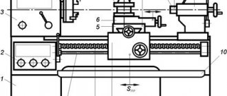
Main components of a manual lathe:
- The bed is the supporting part of the equipment on which all its other elements are located.
- The headstock, which houses the electric motor and drive system that drives the spindle.
- Spindle - supports and rotates the workpiece, which is secured in the collet chuck.
- A tailstock that secures the opposite end of the workpiece (sometimes this includes a rest - a device that supports long workpieces whose rigidity is reduced).
- A support is a reciprocating moving platform on which the working head with a tool is fixed.
Lathes can be controlled by a computer, in which case they are called computer numerical control lathes. All operations performed on such units are automated and controlled by a built-in computer.
Introduction of CNC
A significant breakthrough in the field of machine tool building was the use of the Numerical Program Control system. With the advent of the CNC system, products can now be obtained at lower costs; the cleanliness of processing, as well as accuracy, are at the highest level.
The presence of a CNC system determines the following:
- increased productivity when the cutters are used with a carbide cutting edge;
- processing of both ferrous and non-ferrous, as well as tool alloys is possible with appropriate equipment;
- The intervention of the master in the process is minimal. cutting occurs automatically;
- The CNC system allows you to specify all cutting modes. the CNC program is compiled indicating the speed at which cutting is carried out, as well as the feed;
- often the entire area in which cutting occurs is covered with a protective casing, since the CNC system will not allow you to start working without protecting others;
- the high precision of CNC operation, which is obtained by cutting with the correct speed, allows you to obtain parts with a lower rate of defects for critical elements of various structures.
The CNC system is widely used in the production of lathes in China and the USA. The possibility of implementing CNC is determined by the accuracy of positioning of machine design elements.
Process Features
Metal turning proceeds as follows:
- workpieces installed in the spindle rotate around their axis;
- turning is carried out by approaching the cutter. such tools have different shapes, can be made of tool steel or have carbide cutting edges;
- turning occurs by creating a transverse force by a support in which the cutters are fixed: due to the high friction force and the different hardness levels possessed by the cutters and the workpiece, the workpiece being processed is removed from the metal surface;
- The technology used for turning can be very different: combining longitudinal and transverse feed or using only one.
Considering how cutting occurs on a metal lathe, they all have a similar design.