Threaded parts are a special type of parts that use threads to connect to an object or to each other. In modern industry, the rolling method is often used to apply threaded connections. It consists in the fact that in a metal workpiece, using pressure equipment, the metal is extruded and rolled onto the top of the thread. At the same time, the threaded connection acquires increased strength due to a change in the ductility of the metal. In modern industry, dies, as well as driven or non-driven cylindrical tools, are used to perform rolling.
Goals and purpose
Rolling is a cold method of processing products. Under the influence of the tool, a different pattern is obtained on the surface - mesh, corrugation, scratches, notches. There are no special requirements for surface preparation. The part is ground to the required diameter, then the corrugation is rolled.
Purpose of knurling:
- Improving performance properties.
- Removing cracks and other defects.
- Increased corrosion resistance.
- Improvement of product performance characteristics.
For some parts, knurling is necessary due to their operational characteristics. Corrugation is made on screw heads and handles. For ease of use, rolling is done on the handle on machines and other mechanisms.
Scope of application
Rolling taps can be used when processing workpieces made from the following materials:
- Ferrous and non-ferrous metals.
- Aluminum, copper or zinc.
- Lead alloys.
- Stainless or low carbon steel.
- Bronze with a predominance of copper.
Knurl taps are used when working with through or blind holes. Thanks to the special shape of the working part, the cross-sectional area when the part comes into contact with the tool is significantly increased, which eliminates the possibility of jamming. To extend the service life, the surface of such products can be coated with a protective layer. The most commonly used technologies for this purpose are nitriding and oxidation. The greatest efficiency of chipless rolling taps is ensured when they are used on metalworking machines equipped with self-centering chucks.
Types of rolling
There are two types of knurling used in metalworking. But the meaning of the process does not change.
Form-building
It is used for forming teeth and threads on cylindrical parts, as well as for applying a scale in the production of measuring instruments. In some industries this method is called gear rolling.
Strengthening
Used to increase the wear resistance and strength of the product. When rolling, a hardening is formed on the surface of the part, which improves performance. Used in the manufacture of bushings, shafts, gears and other parts.
“On-pass” knurling technology
Special technique for forming long threads over 250 mm. Features of this method include axial feeding of the workpiece, as well as the formation of a lifting angle at the rollers along the screw line relative to the knurling contour. If we talk about the machines used, then the optimal one would be a unit with an inclined spindle, the design of which will allow the use of roller segments with ring threading. The screw configuration will also be varied - left and right, single and multi-start profiles with strict adherence to a certain pitch are possible. The maximum rolling diameter of this type of thread reaches 200 mm with a pitch of 16 mm. In practice, threaded rods with trapezoidal or metric profiles are often made in this way. To achieve high processing speeds, the machines are equipped with a special transmission, the outboard bearings of which are forcibly lubricated by a built-in mechanism. This allows you to achieve a rotation speed of about 600 rpm.
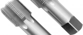
What tools are needed?
The devices are made primarily of tool steel. The tool consists of a holder to which rollers are attached. Depending on the size of the teeth on the roller, a fine, medium and large pattern is obtained.
Knurling rollers
Used to obtain a corrugated surface on a part. The roller is attached to a holder, which is inserted into the tool holder. Rollers can be single-sided or double-sided. To obtain a straight pattern, one roller is used. If mesh corrugation is required, a double-sided tool with the opposite direction of the pattern is used.
Important!
The width and diameter of the roller are selected based on the size of the part.
Serrated
Used to form teeth on cylindrical parts. In most cases, the tool provides the required surface parameters in one pass.
Universal
They are used to form corrugations on handles, screws, as well as to form marks and notches on cylindrical products.
Standard balls
They are made mainly of hard alloys or hardened steel. Ball knurls are additionally equipped with a spring, which ensures uniform pressure on the part. You can adjust the force of pressure of the ball on the surface using a special screw. Balls are used for processing non-rigid parts.
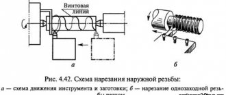
Thread rolling
Produced by extruding metal from a workpiece. Special knurling rollers are used as a tool. Their profile and pitch correspond to the future thread. The rollers are secured into the tailstock quill, or held by the handles manually, as when working with dies.
Features of round thread
This type of cutting can be found on sanitary fittings (regulated by state standard number 13536-68) and on lighting fixtures, as well as on sockets and sockets for them. This variety makes it possible to obtain compounds that are periodically subject to disassembly. The profile for round threaded connections is obtained by mating two arcs with the same radius. The thread pitch is always measured in millimeters, and the letters “Kr” are used as a designation.
Parts used for domestic purposes are equipped with regular round threads
The design features of round knurling provide it with a long service life and significant resistance to loads. The profile does not wear off even with frequent use. Also, such threads can be quite successfully used in systems operating in polluted environments. The round type of threaded connections is used, for example, when coupling railway cars.
How does the process itself happen?
Rolling can be done on any lathe with a powerful tool holder. This type of equipment ensures fast and most accurate transfer of the desired pattern onto the part.
Preparatory work
Preparation begins directly with the installation of knurling in the tool holder. The process itself is similar to fastening the cutter - the holder is completely fixed with bolts, the overhang of the working part is minimal. Before starting work, the rollers are cleaned with a special brush. This is necessary to remove metal dust.
Important!
The tool must be installed strictly in the center.
There is no need to leave an allowance for knurling. The size and shape of the part does not change after corrugation.
Direct knurling
The part is mounted in a three-jaw chuck. The roller is located parallel to the surface being processed. The optimal spindle speed is from 40 to 100 rpm.
With a manual cross feed, the tool is brought to the workpiece, lightly touching it. Next, the knurling is pressed into the surface of the part by 0.5-0.8 mm (must be marked on the cross-feed dial). Afterwards, the tool is fed longitudinally at a speed of 1-2 mm/rev. The roller can be fed automatically or manually.
When the tool passes the specified length, it is necessary to go deeper again by 0.5-0.8 mm and turn on the longitudinal feed in the opposite direction. First you need to make sure that the teeth of the tool fit into the notches already made.
The number of approaches depends on the material being processed. In most cases, it is necessary to run the video 4-7 times. Sometimes the desired pattern is obtained the first or second time.
Reference! After each pass, the workpiece is lubricated with spindle or machine oil, this ensures better surface quality.
Final revisions and verification
You can check the correctness and quality of knurling only by eye. If the corrugation is uniform and without defects, the part can be removed.
GOST 21474-75
STATE COMMITTEE OF STANDARDS OF THE COUNCIL OF MINISTERS OF THE USSR Moscow
DEVELOPED, INTRODUCED AND PREPARED FOR APPROVAL by the All-Union Scientific Research Institute for Normalization in Mechanical Engineering (VNIINMASH)
And about. Director Gerasimov N.N.
Topic leader and performer V.P. Piven
APPROVED AND ENTERED INTO EFFECT by Resolution of the State Committee of Standards of the Council of Ministers of the USSR dated November 24, 1975 No. 3571
UDC 621 At—408.8(083.74] PO Group
STATE STANDARD OF THE USSR UNION
STRAIGHT AND MESH RIFLES Shape and main dimensions
Straight and diamond knurl. Form and basic dimensions
OST 26B16 n OST 26017
Resolution of the State Committee of Standards of the Council of Ministers of the USSR dated November 24, 1975 No. 3571 established the validity period
from 01.01. 77 until 01.01. 87
Failure to comply with the standard is punishable by law
1. The shape and main dimensions of the corrugations must correspond to those indicated in the drawing.
Corrugation profile in direction A
2. Chamfer - according to GOST 10948-64.
3. The pitch of the corrugations P, mm, should be selected from the rows: straight—0.5; 0.6; 0.8; 1.0; 1.2; 1.6;
mesh—0.5; 0.6; 0.8; 1.0; 1.2; 1.6; 2.0.
An example of a symbol for straight corrugation with a pitch of P = 1.0 mm.
Corrugation straight 1.0 GOST 21474—75
Reproduction prohibited Standards Publishing House, 1976
The same, for mesh corrugation with a pitch of P = 1.0 mm:
Corrugation mesh 1.0 GOST 21474—75
4. The height L, angle a and the dependence of the corrugation pitch on the diameter D and width B of the rolling surface are given in the recommended appendix.
APPENDIX Recommended
HEIGHT hf ANGLE a AND DEPENDENCE OF RIFLE PITCH P ON DIAMETER D AND WIDTH IN THE ROLLING SURFACE
1. Corrugation height h: for steel 0.25–0.7 R;
for non-ferrous metals and alloys 0.25-g 0.5 R.
2. a = "70° for corrugations on steel, i = 90° for non-ferrous metals and alloys.
3. The dependence of the pitch P on the diameter and width of the rolled surface is indicated in table. 1 and 2.
The surface deformation processing process has become widespread in industrial production. The turning knurling method is based on the plastic qualities of the metal. This makes it possible to obtain residual deformation without compromising the integrity of the material. This method makes it possible to simplify processing, reduce the amount of waste, and comply with GOST.
Safety precautions
To avoid injury, it is necessary to firmly secure the knurling in the tool holder. When the tool is pressed strongly, non-rigid parts may be pressed out. For such products it is better to use more passes. The edges of the product must have chamfers of sufficient size so that burrs do not remain.
Long parts are fixed at the rear center. The quill overhang should be minimal.
Rolling is used to form a grooved surface on a part. The operation is performed on a lathe with minimal time, so this method is advisable to use in mass production. The knurling pitch is selected depending on the material, size, and purpose of the products.
GEAR CUTTER
The cutting gear is held at an angle to the workpiece by an adjustable holder. When it comes into contact with a rotating workpiece, it also begins to rotate, leaving spiral lines on the material. By changing the angle, you can change the pattern of these lines.
Set the rotation speed to 800-1500 rpm (the slower the workpiece rotates, the easier it is to control the result). Place the flat side of the holder on the tool rest and guide the cutting wheel along the radius of the workpiece at center level. To make the pattern shown in the pictures, we tilted the wheel one notch to the left (relative to the tool handle). You can move the tool along the tool rest to increase the width of the pattern. Such a wheel works not only on end surfaces, but also on those formed by longitudinal fibers.
Nuances of use
To perform the procedure, turning equipment is required - a machine. Before you start working, you need to set the speed on the equipment - no more than 100 per minute. Powerful models and professional machines are able to cope with the task at once. At home, you will need to roll the product several times.
There are four types of rolling:
- direct;
- corner;
- cross;
- semicircular.
The first two options involve the use of one knurling roller. To perform cross knurling you will need two pieces.
A special feature of rollers that perform semicircular rolling is a special semicircular groove with a radius where cutting occurs. To ensure that the part does not go beyond the edges during the procedure, the radius of the groove must exceed the radius of curvature of the part by approximately half the knurling pitch.
Other features of using knurling.
- When direct and cross knurling, it is necessary to take into account the dimensions of the chamfers, otherwise burrs will form on the surface.
- When knurling, the diameter of the product increases by an average of 0.5 knurling steps. This must be taken into account when choosing rollers.
- The knurling pitch is calculated based on several parameters: the diameter and characteristics of the material, as well as the length of the surface to be processed. For example, for hard materials it is worth choosing a large pitch. The same applies to parts with large diameter holes.
The thread rolling procedure should be started before finishing the surfaces of the part. This is explained by the occurrence of large stresses caused by the rollers, due to which the dimensions of the elements may change.
- Almost any machine equipped with a high-power tool holder will be suitable for the task.
- Before carrying out the procedure, the rollers should be thoroughly cleaned with a brush so as not to damage the surface of the material being processed.
Knurling is a complex process, before which it is necessary to take care of the preparation of tools, materials and assembly of the structure. To begin the procedure, you will need to install the roller into the holder. The following types are distinguished:
- floating head holder;
- one- or two-sided;
- U-shaped;
- V-shaped.
Universal models of machines make it possible to work with a pair of rollers at once, due to which it is possible to achieve a cross pattern. Other devices allow you to change the depth of the grooves, expanding the capabilities of the equipment.
Easy rolling of grooves on pipes - REMS groovers!
Briefly about the technology of rolling grooves on pipes.
Modern requirements for the installation of pipeline systems have led to the creation of detachable coupling connections using grooves. Such a connection can withstand pressures that sometimes exceed those of welded and flanged connections. The greater the pressure of the liquid in the pipe on the cuff, the more reliably it seals the connection. Weldless pipelines are used in many high-tech industries, for the transfer of chemical fluids and in recycling systems. A special place is given to them when installing fire sprinkler systems.
GOST R 55430-20136. "Detachable pipeline connections"
establishes requirements to ensure industrial safety during the operation of detachable connections of process pipelines. This standard provides a unified approach to the design, installation and repair of grooved-rolling connections.
The main advantages of the groove joint are:
1. Detachable - easy installation and dismantling. 2. The absence of welding allows work to be carried out in fire and explosive areas. 3. The permissible pressure in the pipeline can reach 50-60 bar. 4. Withstands significant linear expansion. 5. They tolerate and dampen vibration very well.
To obtain a grooved-rolling connection, you will need to roll grooves on the pipes being connected, a collar and a fastening clamp.
For fast and high-quality rolling of grooves, REMS offers two types of grooving machines - electric machines fully equipped for rolling (Rems Collum RG and Magnum RG) and grooving machines (Rems) requiring the use of an additional drive. Rems Amigo and Rems Amigo 2 Compact thread-cutting dies are used as a drive.
Depending on the pipe material, various roller-counter roller rolling sets are used. The knurling rollers are made of particularly strong special steel and have an extremely long service life. The optimal roller/counter roller diameter ratio and large mesh notch guarantee reliable pipe rotation and precise groove rolling. The kits are available for ordinary steel pipes, with Cu marking for copper pipes, with INOX marking for stainless steel pipes, for aluminum and PVC pipes.
Rems groovers roll grooves on steel pipes with a diameter of 1 - 12 "(25 - 300 mm), on stainless pipes with a diameter of 2 - 12" and copper pipes with a diameter of 54 - 159 mm, aluminum pipes and PVC pipes with a diameter of 2 - 12 ".
The Rems Magnum RG groove roller can be easily converted into a thread-cutting machine using a special kit. The complete set includes a universal automatic threading head, BSPT 1/2″-3/4″(R/L) and BSPT 1″-2″(R) threading dies, pipe cutter, deburring device, feed lever, automatic cooling pump and lubricants, oil bath, chip tray. The ultra-stable Hercules XL 12″ support will help you perform high-quality groove rolling or thread cutting. It allows easy movement and rotation in all directions for pipes up to 324 mm in diameter.
Today, the most famous manufacturers of groove couplings (fastening clamp + cuff) are the companies VICTAULIC (USA) and DINANSI (Slovakia).
Source
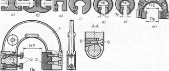
Knurling of grooved surfaces
Types of knurling. The knurling, which is done on surfaces covered by the hand, can be straight (Fig. 217, a) and oblique - mesh (Fig. 217, b). Step S (Fig. 217, c) of direct knurling is done regardless of the material of the part, 0.5-1.2 mm. The pitch of oblique - mesh knurling on parts made of brass and aluminum is 0.6-1.2 mm, and on steel parts - 0.6-1.6 mm. The harder the material of the part and the larger its diameter, the larger the knurling pitch should be.
Fig. 217 Straight (a) and oblique-mesh - (b) knurling and their pitch (S)
Rollers for rolling. The roller for obtaining straight knurling is shown in Fig. 218, a. To obtain oblique - mesh knurling, it is necessary to have two rollers - with left (Fig. 218, b) and with right (Fig. 218, c) notches. The diameter of the rollers is usually taken to be about 20-25 mm, width - 10 mm. The angle α between the sides of the notch (Fig. 218, d) should be taken sharper for rolling hard materials (for example, for machine-made steel α = 70°) and more obtuse if the material of the rolled part is soft (for brass α = 90°).
Rice. 218. Rollers for straight (a) and oblique-mesh knurling - (b, c) knurling and the angle of their notch (d)
Rollers for rolling are made of steel grades U10A, U12A, KhVG, 5KhNM. Rollers made of high-chromium steel grade XE12 work very well.
Roller holders. The holder for the roller used in the formation of straight knurling is shown in Fig. 219, a. Roller 1 is located in slot 2 made in the holder and rotates on axis 3.
Rice. 219. Holder for one (a) and three pairs (b) of rollers
For oblique mesh knurling, you need to have two holders: one with a right roller notch and the other with a left notch. It is better, however, to use a holder with two rollers located one above the other. One roller should have a right and the other a left notch.
In Fig. 219, b shows a universal holder. On the axis 7 there is a cage 6 with three pairs of rollers 4 and 5, the notch of each of which has different steps.
Practice rolling. The knurling is obtained cleanly, without flaws or chipping, if the diameter of the surface prepared for knurling is divided without a remainder by the diameter of the roller. The rolling process is shown in Fig. 220. A holder with one roller is fixed in the tool holder of the machine. The part rotates in the normal direction. The rotation speed of a part made of mild steel should be 20-25 m/min, of a part made of medium hardness - 15-20 m/min.
Rice. 220. Rolling
Knurling to the required depth is obtained after several passes of the roller. The larger the knurling and the harder the material, the more passes must be made. For example, knurling with a pitch of 1.2 mm on a brass part can be obtained in 4-6 passes, and on a steel part - in 6-8 roller passes.
The longitudinal feed of the rollers when rolling parts with a diameter of 10-25 mm should be equal to 1-1.5 mm/rev, and for large diameters - 2-3 mm/rev.
During rolling, the tailstock quill must be extended as little as possible, and the rear center must be pressed tightly against the part, so it must be lubricated more often than usual. The knurling turns out cleaner and smoother if the knurled area is watered with machine oil.
After the rolling is completed, it is necessary to grind chamfers at the ends of the knurled surface - straight (A, see Fig. 217, a) or rounded (B, see Fig. 217, b).
Knurling with dies
View gallery
This technology, on the contrary, is successfully used in hardware production for the serial production of fasteners with normal accuracy. The use of flat dies is characterized by high productivity, while requiring the connection of equipment that is simple in design. This ensures both the reliability of the working process and versatility in the manufacture of parts of different standard sizes. For example, the range of diameters for thread rolling in this case will be 1.7-33 mm. The maximum thread length will be 100 mm, and the pitch distance is within 0.3-3 mm. One of the negative aspects of using dies is the low hardness of parts, since the equipment only works with materials whose tensile strength does not exceed 900 MPa. On the other hand, dies of special modifications make it possible to perform knurling on self-tapping screws and screws in one threaded pass.
Quality control
To ensure that the workpiece has been processed correctly, it is necessary to use thread templates. With their help, the thread pitch is checked.
But for a comprehensive assessment, a thread gauge is used. For convenience, it is installed in a rack and adjusted according to a standard or template, then the movement of the part itself is checked.
You can also use the simplest and most commonly used method. Take a nut or bolt and scroll it over the completed part.
If scuffing is noticeable on the thread as you move, or more effort needs to be applied, then you have made an error in your work. Now you already know how to use a lathe to make various nuts, bolts or threaded connections.
It is important to remember that such parts require great care and tenderness with each pass, and even quality control. It’s better to spend more time on work than to ruin several pieces later