Auxiliary tools (spindle equipment) for multi-purpose machines must meet the following requirements:
- ensure accurate and reliable fastening in the machine spindle or turret;
- ensure accurate and reliable fastening of the tool;
- maintain accuracy throughout the entire service life;
- have high vibration resistance;
- be dynamically balanced depending on the permissible speed or have structural elements for balancing.
Strict requirements for precision tool clamping have led to the predominance of the cylindrical shank for axial tool designs.
Shanks with Morse tapers, CK, NC, MAS-BT and HSK for milling cutters are used very rarely, only for tools of large diameters for particularly difficult working conditions. Shanks HSK, CR, NC, MAS-BT have found the widest application in the designs of auxiliary tools (spindle equipment).
Currently, the following types of cylindrical shanks are widely used.
Cylindrical shank according to DIN 1835A
The cylindrical shank is designed for cutters performing finishing and semi-finishing, including on machines for high-speed processing (spindle speed up to 80,000 min–1). The largest diameter of the tool should not exceed the diameter of the shank. The cutters are fixed in thermal chucks, Tribos type chucks, hydroplastic chucks, hydraulic chucks and collet chucks. The cartridges are listed in order of decreasing clamping accuracy. Thermal chucks and Tribos chucks without adapter cylindrical collets provide the highest:
- fastening accuracy no more than 0.003 mm at the control mandrel overhang 2.5Dfr;
- the highest permissible spindle speed.
Thus, according to the data, this auxiliary tool was tested on stands at rotation speeds of 150,000–250,000 min–1.
The design of a smooth cylindrical shank is shown in Figure 1, dimensions are in Table 1.
Rice. 1. Cylindrical shank according to DIN 1835A
Table 1. Executive dimensions of the cylindrical shank of cutters
| dh6, mm* | 8 | 10 | 12 | 16 | 20 | 25 | 32 | 40 | 50 | 63 |
| L+2, mm | 36 | 40 | 45 | 48 | 50 | 56 | 60 | 70 | 80 | 90 |
| s, mm | 0,8 | 1,0 | 1,2 | 1,6 | 2,0 | 2,0 | 2,0 | 2,0 | 2,0 | 2,0 |
Note.* - a number of tool manufacturers recommend making the tool shank according to dh5.
For Tribos chucks, hydroplastic, hydraulic and collet, the use of adapter cylindrical collets is acceptable. The use of adapter collets reduces the required number of cartridges, but causes a decrease in the accuracy of fastening and the transmitted moments and axial forces.
The minimum length of the shank included in the collet depending on the base diameter of the chuck, and the coefficients for reducing the transmitted loads are given in tables 2, 3.
Table 2. Minimum length of the section for fastening cylindrical cutter shanks
| Cutter shank diameter | 8 | 10 | 12 | 16 | 20 | 25 | 32 | 40 | 50 | 63 |
| Shank length L+2, mm | 36 | 40 | 45 | 48 | 50 | 56 | 60 | 70 | 80 | 90 |
| Basic diameter of the cartridge, mm | Minimum length of the fastening section lз, mm | |||||||||
| 12 | 40 | |||||||||
| 20 | 40 | 40 | 40 | 45 | ||||||
| 25 | 33 | 36 | 42 | 44 | 46 | |||||
| 32 | 40 | 40 | 40 | 40 | 40 | 45 | ||||
Note. The minimum length of the section for fastening the cylindrical shank should not be less than the working part of the cylindrical collet. If this condition is not met, the adapter collet creates an uneven load on the cutter shank and, therefore, transmits less torque. This is most acutely manifested when the grooves are located on one side on a cylindrical collet.
Table 3. Reduction factors for transmitted loads
| Cutter shank diameter | 8 | 10 | 12 | 16 | 20 | 25 | 32 | 40 | 50 | 63 |
| Basic chuck diameter | Transmitted load reduction factor | |||||||||
| 12 | 0,44 | 1 | ||||||||
| 20 | 0,12 | 0,19 | 0,28 | 0,55 | 1 | |||||
| 25 | 0,06 | 0,1 | 0,17 | 0,32 | 0,53 | 1 | ||||
| 32 | 0,04 | 0,07 | 0,09 | 0,17 | 0,26 | 0,46 | 1 | |||
Types of drills depending on the shape of the working body
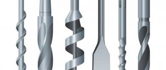
The types of drills and their purpose are closely related. Based on the type of working body, the following types are distinguished:
- Screw or spiral. This is one of the most widely used drill shapes. It is used to work with a variety of substances. Universal drills also have a spiral design. Their sizes range from tenths of a millimeter to tens of centimeters.
- Flat or feather. Used for holes in soft substances, wood, foam concrete. The working body is a sharpened blade, in the middle of which there is a sharp protrusion for centering.
- Deep drilling. Used if the hole depth is at least five times greater than the diameter. There are two screw cavities in the body of the drill, through which cutting fluid is supplied to the drilling zone
- Single sided cut. Used for high precision machining. They have a supporting plane and a pair of working edges located on one side of the longitudinal axis.
- Crown. The shape is a hollow cylinder; the cut is made with the lower edge. As a result, a ring is cut through the material, and a core is located inside it - a solid cylindrical piece of material. At the end of the operation, it must be shaken out of the crown.
- Centering. For preliminary drilling, mark the center.
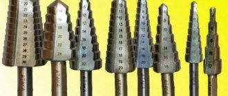
- Stepped. It is a stepped cylindrical pyramid. A progressive type of equipment, used for sheet metal for large diameters. With a gradual increase in diameter, the sheet does not deform.
Feather drill
Core drill
Types of drills are also divided according to the shape of the resulting hole:
- conical types - the diameter gradually decreases with depth;
- stepped types - the diameter decreases in leaps and bounds;
- cylindrical types - the diameter is constant throughout the entire depth.
There are other types. They are used for highly specialized cases.
Cylindrical shank type WELDON according to DIN 1835B
Weldon-type cylindrical shanks are designed for roughing and semi-finishing cutters; the main disadvantage is the increased runout of the cutting edges due to fastening with screws in the radial direction. It should be noted that the opinion about increased runout of the cutting edges will be justified structurally only when compared with thermal chucks and Tribos-type chucks. When using adapter cylindrical collets, the accuracy of tool clamping for Tribos, hydraulic, hydroplastic, collet chucks may be lower. This makes it possible to use Weldon chucks in justified cases, even for finishing milling. Fastening errors for various cartridge designs are shown in Figures 2, 3.
The design of the shank is shown in Figure 4, the dimensions are in Table 4.
Rice. 2. Maximum runout of the cutting edges of cutters with cylindrical shanks when secured in various types of chucks with cylindrical collets of normal accuracy
Rice. 3. Maximum runout of the cutting edges of cutters with cylindrical shanks when secured in various types of chucks with high-precision cylindrical collets
Rice. 4. Cylindrical shank according to DIN 1835B
Table 4. Dimensions of a cylindrical Weldon type shank
| dh5, mm | 8 | 10 | 12 | 16 | 20 | 25 | 32 | 40 | 50 | 63 |
| L+2, mm | 36 | 40 | 45 | 48 | 50 | 56 | 60 | 70 | 80 | 90 |
| Ll-1 | 18 | 20 | 22,5 | 24 | 25 | 32 | 36 | 40 | 45 | 50 |
| h, mm | 6,6 | 8,4 | 10,4 | 14,2 | 18,2 | 23 | 30 | 38 | 47,8 | 60,8 |
| b+0.05, mm | 5,5 | 7 | 8 | 10 | 11 | 12 | 14 | 14 | 18 | 18 |
| b1+1 , mm | 17 | 19 | 19 | 23 | 23 | |||||
| a, mm | 0,8 | 1,0 | 1,2 | 1,6 | 2,0 | 2,0 | 2,0 | 2,0 | 2,0 | 2,0 |
Shanks with flats are not allowed to be used in thermal chucks, hydroplastic, hydraulic, or collet. For chucks that use elastic deformation (Tribos) for fastening, their use is permitted. Their use will lead to residual deformations and, accordingly, to a premature loss of accuracy. When processing long surfaces under conditions of intense vibration, when fastening cutters in Weldon chucks, cases of self-loosening of the fastening screws may occur.
Recommendations for selection
To select the right tool for the best performance and surface quality, you need to consider:
- characteristics of the part material;
- diameter;
- depth.
The most important drill parameters are:
- diameter;
- length;
- design features;
- type and sharpness of sharpening;
- working part material;
- working surface color;
- balance;
- appointment;
- compatible equipment.
Thus, an SDS shank will require an appropriate chuck, and large-diameter drilling in metal workpieces requires a powerful, low-speed machine or high-torque drill.
Cylindrical threaded shank
Mills with cylindrical threaded shanks are currently in limited use due to the complexity of collet and threaded collet designs and the high permissible runout of the cutting edges of the cutters. Area of application: rough milling.
The design of the shank is shown in Figure 5, the dimensions are in Table 5.
Rice. 5. Cylindrical threaded shank
Table 5. Executive dimensions of the cylindrical shank of threaded cutters
| Dh6, mm | 8 | 10 | 12 | 16 | 20 | 25 | 32 | 40 | 50 | 63 |
| L+2, mm | 36 | 40 | 45 | 48 | 50 | 56 | 60 | 70 | 80 | 90 |
| s, mm | 0,8 | 1,0 | 1,2 | 1,6 | 2,0 | 2,0 | 2,0 | 2,0 | 2,0 | 2,0 |
| m | 8 | 10 | 12 | 16 | 20 | 24 | 30 | 38 | 47 | 60 |
| S, mm | 1 | 1,25 | 1,25 | 1,5 | 1,5 | 2 | 2 | 2 | 2 | 2 |
| l, mm | 8 | 10 | 12 | 14 | 14 | 16 | 16 | 20 | 20 | 20 |
Drill surface color
The color of the surface can tell a lot about the material from which the instrument is made.
- Grey. It's just steel, and inexpensive. This type of drill is not subjected to additional processing to improve cutting or strength properties. It makes sense to use them only when you need to drill a couple of holes every two weeks.
- Black. This is the result of hardening by superheated steam. Decent, durable enough mass-produced tools for household use. Maintain affordability
- Light golden. Such tools have undergone tempering heat treatment, which significantly increases strength and relieves internal stress. They are noticeably more expensive, but they justify their price due to their long service life.
- Bright golden. Titanium is added to the alloy. This is the best type of drill available for home use. Titanium reduces friction and therefore heat. This allows for excellent service life. But the price rises accordingly. The purchase is economically justified for large volumes of work.
Types of drills by surface color
The general pattern is that more expensive drills have to be changed less often. If the volume of upcoming work is significant, then it is better not to save money and then not buy dozens of cheap drills. In addition to saving money, invaluable time will be saved and the risk of material damage if the drill breaks is significantly reduced.
Cylindrical shank with wedge flat
These shanks have higher reliability of tool fastening compared to Weldon shanks when machining long surfaces under vibration conditions.
Rice. 6. Cylindrical shank with wedge flat for tools with a diameter of 6 to 20 mm
Due to the wedge, during fastening, an axial component of the fastening force arises, which counteracts the axial component of the milling force. Clamping accuracy is the same as for Weldon shanks.
Shank designs for tools with a diameter of 6–20 mm are shown in Figure 6, for diameters of 25–32 mm - in Figure 7.
The standard dimensions of the shanks are given in Table 6.
Rice. 7. Cylindrical shank with wedge flat for tools with a diameter of 25 to 32 mm
Table 6. Design dimensions of shanks with wedge flats
| d16 | b2 | b3 | h2H11 | l1–0+2 | l4–1+0 | l5 | r2min | |
| 6 | 4,3 | 5,1 | 36 | 25 | 18 | 1,2 | ||
| 8 | 5,5 | 6,9 | 36 | 25 | 18 | 1,2 | ||
| 10 | 7,1 | 8,5 | 40 | 28 | 20 | 1,2 | ||
| 12 | 8,2 | 10,4 | 45 | 33 | 22,5 | 1,2 | ||
| 14 | 8,1 | 12,7 | 45 | 33 | 22,5 | 1,2 | ||
| 16 | 10,1 | 14,2 | 48 | 36 | 24 | 1,6 | ||
| 18 | 10,8 | 16,2 | 48 | 36 | 24 | 1,6 | ||
| 20 | 11,4 | 18,2 | 50 | 38 | 25 | 1,6 | ||
| 25 | 13,6 | 9,3 | 23 | 24,1 | 56 | 44 | 32 | 1,6 |
| 32 | 15,5 | 9,9 | 30 | 31,2 | 60 | 48 | 35 | 1,6 |
Wood drills
Small diameter holes (up to 15 mm) in wood, plywood, OSB can be easily made with a metal drill. If increased precision and surface smoothness are required, special carbon steel drills are used, which have special structural elements and are not suitable for processing metal parts. The following types are distinguished:
- Spiral. They have a specific sharpening that allows you to obtain the best surface quality.
- Screw. They have a sharp cutting edge and are made in the form of a screw. This makes it easier to remove chips from deep holes.
- Feathers. Allows you to work on large diameters - up to 50 mm. Cheap and simple in design. The surface quality and dimensional accuracy are lower than those of screw ones.
- Crowned. They look like a crown. The diameter reaches 150 mm.
Wood drills
Tapered shank according to DIN 69871 B for CNC machines with central coolant supply through the flange
The shank is recommended for use on end mills for roughing and end mills for both roughing and finishing (thin) milling with coolant supply through the machine spindle.
The design of the shank is shown in Figure 10, the dimensions are in Table 11.
Rice. 10. Tapered shank according to DIN 69871 B for CNC machines with central coolant supply through the flange
Table 11. Design dimensions of cones 7:24 for coolant supply through the flange
| NC | el–0.1+0.1 | e2max | d5 | NC | el–0.1+0.1 | e2max | d5 |
| 30 | 21 | 5 | 4 | 45 | 35 | 6 | 5 |
| 40 | 27 | 5 | 4 | 50 | 42 | 7 | 6 |
Shackle rod
Drill Shank Tie
This shank was common before 1850 and is still in production. At first, the tapered shank was simply driven into a square hole at the end of the drill. Over time, various cartridge designs have been invented, and modern cartridges can effectively grip and control this shank.
It was difficult to find a reference to the entry angle of the cone, but 7 different bits were measured and they all had an entry angle of 8 ± 0.25 degrees.
- Easy to make in a forge
- Very wide tolerances allowed (not very precise)
- Moderate torque transmission but no slippage with round shanks
- Requires matching cartridge
10. Tapered shank for CNC machines according to Japanese standard MAS BT403
The shank is recommended for use on end mills for roughing and end mills for both roughing and finishing (thin) milling on machines with a spindle made according to the Japanese standard MAS BT403. The degree of accuracy of the AT3 shank, the largest diameters of the cutters are given in Table 13.
The design of the shank is shown in Figure 13, dimensions - in Table 14.
Table 13. Recommended largest cutter diameters
| Shank designation MAS VT403 | 50 | 45 | 40 |
| Largest cutter diameter, mm | 80 | 63 | 50 |
Rice. 13. Tapered shank for CNC machines according to Japanese standard MAS BT403
Table 14. Design dimensions of cones 7:24 for programmed machines according to the Japanese standard MAS VT403
| VT | a±1 | bn12 | h2 | d | d1 | d2-0.5 | d3-0.1 |
| 40 | 2 | 16,1 | 21 | 44,45 | M16 | 53 | 63 |
| 45 | 3 | 19,3 | 26 | 57,15 | M20 | 73 | 85 |
| 50 | 3 | 25,7 | 31 | 69,85 | M24 | 85 | 100 |
| d4±0.5 | Dmax | h±0.1 | h1±0.1 | L-0.3 | L1min | L2-0.4 | d6 |
| 75,68 | 50 | 16,6 | 27 | 65,4 | 30 | 22,6 | 17 |
| 100,22 | 63 | 21,2 | 33 | 82,8 | 38 | 29,1 | 21 |
| 119,02 | 80 | 23,2 | 38 | 101,8 | 45 | 35,4 | 25 |
The best manufacturers
The reputation of the manufacturer is a very important criterion when selecting a drill. Many companies are proud of a hundred and two hundred year history of impeccable quality.
Bosch drills
Many technologists agree that the best price/performance ratio on the market today is:
- Enterprises of the CIS countries. Their products have traditionally, since the times of the USSR, been distinguished by their strength and durability at a low price. Unfortunately, they are gradually leaving the market
- At an affordable price, Ruko provides decent quality and a wide range of designs, coatings, diameters, lengths and sharpenings.
- Bosh. It costs more, but has a significantly greater resource. Beneficial for large volumes of work.
- Bison A worthy attempt to revive the glory of Soviet instrumentalists. Combines high quality and reliability with reasonable prices.
Tapered shank for CNC machines type HSK DIN 69893 form A
The shank is recommended for use on end mills for roughing and end mills for both roughing and finishing (thin) milling. The largest cutter diameters are given in Table 15.
The design of the shank is shown in Figure 14, dimensions - in Table 16.
Currently, HSK125 and HSK160 shanks have been additionally developed for heavy-duty applications.
Table 15. Recommended largest cutter diameters
| Shank designation HSK-A | 100 | 80 | 63 | 50 | 40 | 32 |
| Largest cutter diameter, mm | 85 | 67 | 53 | 42 | 34 | 26 |
Rice. 14. Tapered shank for CNC machines type HSK DIN 69893 form A
Table 16. Design dimensions of cone type HSK-A according to DIN 69893
| HSK-A | b1±0.04 | b2H10 | b3H10 | d1h10 | d2 | d5H11 | d10max | d11-0.1 |
| 32 | 7,05 | 7 | 9 | 32 | 24 | 20,5 | 26 | 26,5 |
| 40 | 8,05 | 9 | 11 | 40 | 30 | 25,5 | 34 | 34,8 |
| 50 | 10,54 | 12 | 14 | 50 | 38 | 32 | 42 | 43 |
| 63 | 12,54 | 16 | 18 | 63 | 48 | 40 | 53 | 55 |
| 80 | 16,04 | 18 | 20 | 80 | 60 | 50 | 67 | 70 |
| 100 | 20,02 | 20 | 22 | 100 | 75 | 63 | 85 | 92 |
| d12-0.1 | f1-0.1 | f 2min | f3±0.1 | h1-0.2 | l1-0.2 | l6js10 | r3±0.02 | |
| 37 | 20 | 35 | 16 | 13 | 16 | 8,92 | 1,38 | |
| 45 | 20 | 35 | 16 | 17 | 20 | 11,42 | 1,88 | |
| 59,3 | 26 | 42 | 18 | 21 | 25 | 14,13 | 2,38 | |
| 72,3 | 26 | 42 | 18 | 26,5 | 32 | 18,13 | 2,88 | |
| 88,8 | 26 | 42 | 18 | 34 | 40 | 22,85 | 3,88 | |
| 109,75 | 29 | 45 | 20 | 44 | 50 | 28,56 | 4,88 |
Tapered shank for CNC machines type HSK DIN 69893 form C
The shank is recommended for use on end mills for roughing and end mills for both roughing and finishing (thin) milling on machines with manual tool change . The largest diameters of end mills are given in Table 17.
The design of the shank is shown in Figure 15, dimensions - in Table 18.
Table 17. Recommended Largest End Mill Diameters
| Shank designation HSK-C | 80 | 63 | 50 | 40 | 32 |
| Largest cutter diameter, mm | 67 | 53 | 42 | 34 | 26 |
Rice. 15. Tapered shank for CNC machines type HSK DIN 69893 form C
Table 18. Design dimensions of cone type HSK-C according to DIN 69893
| HSK-C | d1H10 | d2 | d5H11 | d16 | l1-0.2 | l6js10 | f5-0.1 | b1 | r3±0.02 |
| 32 | 32 | 24 | 20,5 | 4 | 16 | 8,92 | 10 | 7,05 | 1,38 |
| 40 | 40 | 30 | 25,5 | 4,5 | 20 | 11,42 | 10 | 8,05 | 1,88 |
| 50 | 50 | 38 | 32 | 6 | 25 | 14,13 | 12,5 | 10,54 | 2,38 |
| 63 | 63 | 48 | 40 | 7,5 | 32 | 18,13 | 12,5 | 12,54 | 2,88 |
| 80 | 80 | 60 | 50 | 8,5 | 40 | 22,85 | 16 | 16,04 | 3,88 |
| 100 | 100 | 75 | 63 | 12 | 50 | 28,56 | 16 | 20,02 | 4,88 |
How to understand the markings
Markings can tell everything about the size, type and material from which the drill is made. For small diameters (up to 2 millimeters), markings are not applied to the instrument itself; the boxes in which it is stored are marked.
Drills from 2 to 3 mm have a diameter designation on the shank accurate to tenths and the grade of the alloy from which they are made
Drills thicker than 3 mm are marked with diameter, material designation and manufacturer’s logo.
Explanation of NHD drill markings
Additional characters may be added to the inscription:
- P are high-speed tool alloys;
- M - molybdenum additives;
- K - cobalt additives;
- etc.
Many foreign manufacturers put more detailed information on the shank:
- country of origin;
- manufacturer's label;
- grade of tool alloy;
- diameter;
- the maximum accuracy class achievable by this tool;
- list of materials recommended for drilling.
Tapered shank for CNC machines type HSK DIN 69893 form E
The shank is recommended for use on end mills for roughing and finishing and end mills for both roughing and finishing (thin) milling. The area of application of the shank is machines for high-speed processing. The largest end diameters of the cutters are given in Table 19.
The design of the shank is shown in Figure 16, and the dimensions are shown in Table 20.
Table 19. Recommended largest end mill diameters
| Shank designation HSK-E | 63 | 50 | 40 | 32 | 25 |
| Largest cutter diameter, mm | 53 | 42 | 34 | 26 | 20 |
Rice. 16. Tapered shank for CNC machines type HSK DIN 69893 form E
Table 20. Design dimensions of cone type HSK-E according to DIN 69893
| HSK-E | d1h10 | d2 | d4max | d5-0.1 | d6-0.1 | f1-0.1 | f2min | f3±0.1 | l1-0.2 | l4js10 |
| 25 | 25 | 19 | 20 | 22 | 28,5 | 10 | 20 | 4,5 | 13 | 7,21 |
| 32 | 32 | 24 | 26 | 26,5 | 37 | 20 | 35 | 16 | 16 | 8,92 |
| 40 | 40 | 30 | 34 | 34,8 | 45 | 20 | 35 | 16 | 20 | 11,42 |
| 50 | 50 | 38 | 42 | 43 | 59,3 | 26 | 42 | 18 | 25 | 14,13 |
| 63 | 63 | 48 | 53 | 55 | 72,3 | 26 | 42 | 18 | 32 | 18,13 |
Popular brands of instruments from foreign manufacturers
To choose the right imported drill for your materials, you should understand their designation system. The most common types of designation are:
HSS-R and HSS-G
They can drill:
- steel castings, carbon and low-alloy alloys;
- non-ferrous alloys;
- cast iron parts.
HSS-G Co 5
For medium strength steels:
- high carbon;
- stainless steel;
- thermally strengthened;
- resistant to aggressive environments;
- highly alloyed.
HSS-G TiAN/TiN
Drills with titanium coating and additives of aluminum and nitrogen compounds. They are characterized by high wear resistance and corrosion protection.
Drills brand HSS-G TiAN
Recommended for working with high-strength materials
- cast irons with carbon in spherical form;
- high-strength bronze and brass;
- injection moldings
There are other types of tool steel. They serve for industrial and highly specialized applications
Morse taper shank
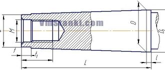
The shank is recommended for use on end mills for roughing and semi-finishing. The advantages are a large transmitted torque and the absence of axial displacement of the cutter under the influence of cutting forces. The recommended degree of accuracy is AT3–AT5. Disadvantages - increased runout of the cutting edges of the tool compared to cylindrical shanks.
The design of the shank is shown in Figure 17, the dimensions are in Table 21.
Morse shanks are not suitable for cutters operating at rotation speeds above 6000 rpm.
Rice. 17. Morse taper for cutters
Table 21. Executive dimensions of Morse cones
| № | d | d1 | d2 | d3 | a | Lmax | L1max | L2min | L3min | L4 |
| 0 | 9,45 | 9,2 | 6,4 | 3,0+1,2 | 53 | 50 | 4 | |||
| 1 | 12,065 | 12,2 | M6 | 9,4 | 3,5+1,4 | 57 | 53,5 | 16 | 22 | 5 |
| 2 | 17,780 | 18 | M10 | 14,6 | 5,0+1,4 | 69 | 64 | 24 | 31,5 | 5 |
| 3 | 23,825 | 24,1 | M12 | 19,8 | 5,0+1,7 | 86 | 81 | 24 | 33,5 | 7 |
| 4 | 31,267 | 31,6 | M16 | 25,9 | 6,5+1,9 | 109 | 102,5 | 32 | 42,5 | 9 |
| 5 | 44,399 | 44,7 | M20 | 35,7 | 6,5+1,9 | 136 | 129,5 | 40 | 52,5 | 10 |
Connection points for face mills
The designs of the connecting points of end mills are shown in Figures 18–20, the dimensions are in Tables 22–25.
For large-diameter cutters, the connecting points can be made like a tool with a radial arrangement of carbide inserts.
Rice. 18. Connecting places for face mills
Table 22. Connections for face mills
| D | dn6 | H | tn11 | bn11 | Lmin | d1min | d2min | dst |
| 32 | 16 | 40 | 8,4 | 5,6 | 19 | 13,5 | 8,4 | 32 |
| 40 | 16 | 40 | 8,4 | 5,6 | 19 | 13,5 | 8,4 | 32 |
| 50 | 22 | 40 | 10,4 | 6,3 | 20 | 18 | 11 | 40 |
| 63 | 22 | 40 | 10,4 | 6,3 | 20 | 18 | 11 | 42 |
| 80 | 27 | 50 | 12,4 | 7 | 22 | 20 | 13 | 52 |
| 100 | 32 | 50 | 14,4 | 8 | 25 | 27 | 17 | 62 |
| 125 | 40 | 63 | 16,4 | 9 | 29 | 32 | 21 | 72 |
Rice. 19. Connecting places for face mills
Table 23. Connections for face mills with radial placement of carbide inserts
| D | h6 | H | tH11 | bH11 | Lmin | d1min | d2min | dst |
| 32 | 16 | 40 | 8,4 | 5,6 | 19 | 13,5 | 8,4 | 32 |
| 40 | 16 | 40 | 8,4 | 5,6 | 19 | 13,5 | 8,4 | 32 |
| 50 | 22 | 40 | 10,4 | 6,3 | 20 | 18 | 11 | 40 |
| 63 | 22 | 40 | 10,4 | 6,3 | 20 | 18 | 11 | 42 |
| 80 | 27 | 50 | 12,4 | 7 | 22 | 20 | 13 | 52 |
| 100 | 32 | 50 | 14,4 | 8 | 25 | 27 | 17 | 62 |
| 125 | 40 | 63 | 16,4 | 9 | 29 | 32 | 21 | 72 |
Table 24. Connections for face mills with tangential placement of carbide inserts
| D | dn6 | H | tn11 | bn11 | Lmin | d1min | d2min | dst |
| 80 | 32 | 50 | 14,4 | 7 | 22 | 20 | 13 | 58 |
| 100 | 40 | 50 | 16,4 | 8 | 27 | 27 | 17 | 70 |
| 125 | 50 | 63 | 16,4 | 9 | 30 | 32 | 21 | 72 |
| 160 | 50 | 63 | 16,4 | 9 | 30 | 32 | 21 | 72 |
| 200 | 50 | 63 | 16,4 | 9 | 30 | 32 | 21 | 72 |
Rice. 20. Connections for face mills of large diameters
Table 25. Connections for face mills
| D | D1 | dn6 | H | tH11 | bn12 | L | d1min | D2min | D3min | dst |
| 160 | 66,7 | 40 | 63 | 16,4 | 9 | 31 | 56 | 14 | 20 | 90 |
| 200 | 101,6 | 60 | 63 | 25,7 | 14 | 32 | 70 | 18 | 26 | 140 |
| 250 | 101,6 | 60 | 63 | 25,7 | 14 | 32 | 70 | 18 | 26 | 170 |
Drills for stone materials
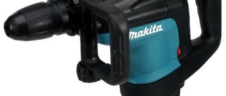
Regular drill bits are not suitable for drilling into concrete, brick or stone. They quickly become dull on grains of sand and stone particles that have abrasive properties. In addition, a compacted layer of tiny particles of material is created in front of the drill. This layer is sintered by frictional heating. Therefore, both the drill itself and the drilling technology have their own characteristics. A reciprocating motion is added to the rotation of the tool, crushing the material. This is how a hammer drill, a more powerful hammer drill, and a boring drill work. A slightly larger diameter plate made of a particularly hard alloy (for example, Pobedit) is fused into the head of the tool. For larger diameters and depths, a crown with carbide teeth or with embedded industrial diamonds is used.
Concrete drill

