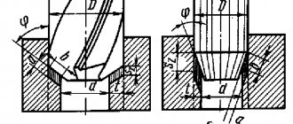
Conical countersink - a tool for forming a cone-shaped recess at the inlet part of the hole for the fastener. Countersinking holes allows you to hide the countersunk heads of screws, bolts, screws or rivets flush with the surface. This operation is performed at low speeds of a metalworking machine or hand drill.
The production of countersinks is regulated by GOST 14953-80
and foreign standards
DIN 334
,
DIN 335
, etc. The main characteristics of the tool are the diameter and angle of the cone at the apex. According to the domestic standard, the tool is produced with an angle of 60°, 90°, 120° and an outer diameter from 5 to 80 mm. The cone angle of the cutting part of the countersink corresponds to a specific profile of the hardware head.
Screws and screws with countersunk heads of 90° are most common in our country, while, for example, in America, inch fasteners with a head cone of 82° (UNC, UNF thread) are more common. Screws with British thread BSF, BSW can have 100º. An angle of 75° is common among hammer rivets, while 100º and 120° are common among blind rivets. In the aerospace industry, countersunk fasteners typically have an angle of 100°.
The essence of the countersinking process
Countersinking and drilling are closely related. Typically, countersinking is carried out along a finished hole, but there are cases when it is necessary to make a recess without pre-drilling. In both versions, a countersink tool of different designs is used.
The countersinking process itself is very simple: a special cutter is used to chamfer the hole. The more metal removed, the larger the depression. The countersink shape is usually conical. The main thing here is to maintain strict alignment of the cutting element and the hole: there must be perfect alignment. Otherwise, there will be a displacement of the recess relative to the hole, and the screw head will not be able to fit into it.
To perform a countersinking operation to obtain chamfers and recesses, it is necessary to go through the following process steps:
- Measure the head of the threaded hardware for which the recess will be made (this means both the diameter, height, and bevel angle if the head has a countersunk design).
- Select the appropriate countersink and secure it in the drilling or turning equipment.
- Strictly observing the relationship of the axes, fasten the workpiece with the hole opposite the cutter.
- Turn on the drilling equipment and set the required number of revolutions (if the circuitry of the machine allows it) or deliberately select the necessary tool for the equipment parameters.
- Countersink the hole.
This is interesting: Bending a profile pipe: making a pipe bending machine with your own hands
Differences between countersinking and countersinking
Countersinking and countersinking are completely different hole processing operations.
The countersinking process involves the impact on the entire drilled channel. And the purpose of countersinking is to level this hole, to make it better in terms of all geometric parameters and the cleanliness of the channel surface. For countersinking, a special tool (countersink) has been developed, the main knives of which are arranged in a spiral along the entire body of the tool (the length of the body, as a rule, exceeds the length of the hole channel). The countersink only works on part of the hole at the beginning. Its main task is to make a countersunk or chamfer. Therefore, the tool mainly has knives at the end. The only thing that a countersink and a countersink have in common is that they are driven using the same machines.
Follow the rules when working with a counterbore
When performing counterboring, you must adhere to a number of rules:
- When counterboring open surfaces, it is recommended to fix a stop on the tool shank. The simplest method is to use a thrust nut with a lock nut.
- When counterboring recesses for hardware heads, a tool with a vertex angle of 90° is used. Reducing the angle is carried out in cases where, after counterboring, a cut remains on the surface of the hole being machined.
- Making holes for hardware is carried out in two stages. First, a hole is drilled to a certain diameter, then the hole is given the desired shape and size by counterbore.
- The counterbore guide should not be in full contact with the bushing. Contact with screw strips is acceptable. Violation of this rule can lead to jamming of the counterbore in the bushing as a result of strong heating of the workpiece and metal-cutting tool under the influence of high rotation speed of the machine spindle.
- Hole alignment is ensured through the use of counterbores with guides.
- When securing an end countersink in a quick-change chuck, it is recommended to place the cutting teeth at both ends.
- To process workpieces made of high-hard metals, you should use tools with carbide inserts.
- For processing brittle alloys, it is recommended to use single-tooth screw end countersinks with a radially located front surface.
Compliance with the rules guarantees perfectly accurate sized holes.
Types of counterbores
We will describe what the tool looks like, what elements it consists of, and what modifications there are.
Design features (information and drawings)
Countering
- a cylindrical tool of axial type with cutting teeth located in the end part. There are grooves on the side surfaces of the product that are designed to remove metal shavings from the work area.
Image No. 2: Countering device with replaceable guide pin
Types of counterbores
The designation of the counterbore in the drawing is given in GOST 26258-87. The same regulatory document defines the technological features of the production of cutting tools and divides them into categories. According to the classification, the following are produced:
- counterbores with cylindrical shanks and guide pins, which are integral with the tool;
- tools with conical shanks and removable trunnions;
- attachment-type products in the form of cutting heads (put on frames with conical shanks, the axle is replaceable);
- tools with replaceable trunnions and shanks, which are mounted in pin locks of machines.
Image No. 3: Varieties of counterbores
The working parts of the instruments are manufactured:
- entirely made of high-speed steel;
- with carbide tipped.
Counterbodies for metal have a different number of working blades. Products with cylindrical shanks are equipped with two to four blades. All other varieties - four.
The type of shank affects how exactly the tool is fixed in the machine.
- Counters with cylindrical shanks are installed in chucks.
- Tools with conical shanks are mounted in mounting holes, Morse tapers.
- Products with shanks for fastening in pin locks are used together with machines equipped with these fittings.
Requirements for the production of counterbores according to GOST
Requirements for the manufacture of counterbores are regulated by GOST 26258-87. This document indicates that attachment-type tools, the diameters of the working parts of which are less than 8 mm with cylindrical shanks, are produced in one piece. And counterbores with cutting parts larger than 8 mm have a welded structure.
Image No. 4: Materials that go into the production of counterbores with all-metal working parts
The central rods of the products, as well as the shanks, are made of steel grades 45 and 45X. There are two types of material used for cutting parts.
- High-speed steel - the requirements for it are set out in GOST 19265.
- Carbide plates VK6, VK6M, T5K10, T5K6 - requirements for material characteristics are described in GOST 3882, for geometry and dimensions - in GOST 25400.
Image No. 5: Materials that go into the production of counterbores with carbide inserts
Carbide plates are attached to the working parts of the tools with solders of the MNMts 68-4-2 grade and L63 or L68 brass. The minimum solder thickness is 2/10 mm.
Types of Hole Making Tools
GOST 14953-80.
conical countersinks. technical specifications (with changes n 1, 2) Both the countersink and the countersink in their geometric parameters must comply with the requirements indicated by the corresponding GOST or Technical Specifications (TU). The working part of the countersink consists of many cutting blades. It is used to process holes previously obtained by drilling. Depending on the design and scope of application, the following types of countersinks are distinguished.
- Cylindrical tools, the working part of which is coated with a wear-resistant material. Countersinks of this type, the requirements for which are regulated by GOST 12489-71, are produced with diameters from 10 to 20 mm.
- Solid countersinks of conical type, produced in the diameter range of 10–40 mm. The material for the manufacture of these tools, the characteristics of which must meet the requirements of TU 2-035-923-83, can be alloyed high-speed steel, as well as tool steel alloys. At the same time, a wear-resistant coating is applied to the working surface of such a countersink. Tools belonging to this category can be used for machining holes made in steel and cast iron parts.
- Countersinks are of one-piece mounted type, the diameter of which can be in the range of 32–80 mm. They are manufactured in accordance with the requirements established by GOST 12489-71.
- Conical countersinks, which can be of two types: type 1, produced in accordance with GOST 3231-71, and type 2 - a mounted countersink, the requirements for the characteristics of which are regulated by the provisions of the same regulatory document. The two types of countersinks differ only in the presence of plates on their working part, which are made of carbide material.
Countersink with guide pin
A countersink also belongs to the category of multi-blade cutting tools, but it is distinguished from a countersink by a list of technological tasks that can be solved with its help. In particular, using it, you can make recesses in pre-made holes, form chamfers on their surface, etc. The following types of countersinks are distinguished depending on their design.
- Conical countersinks, the working surface of which can be manufactured with angles of 60, 90 and 120°. The production of such countersinks is regulated by GOST 14953-80E, and they are used for processing holes for fasteners, metal products, as well as for removing internal chamfers.
- Countersinks are cylindrical type, which can be produced with a conical or cylindrical shank, as well as with a wear-resistant coating on the working surface. The regulatory document, the provisions of which regulate the requirements for the characteristics of cylindrical countersinks, is GOST 2I22-2-80. Using such a tool, support-type surfaces are usually processed.
Zenker: description and classification
As noted above, countersinks are a type of multi-bladed metal-cutting tool. They allow you to achieve class 4–5 accuracy when machining holes. They are also widely used for semi-finishing before further mechanical or manual reaming. According to their design, they are divided into several types:
- tail;
- mounted;
- solid;
- prefabricated
Outwardly, they resemble a regular drill, but have a larger number of cutting edges. The accuracy of the size of the hole being machined is achieved through the calibrating part. The tool is secured in the machine chuck using a shank. They are usually made from high-speed alloy tool steel or high-alloy carbide steel. Devices made of tool alloys have a cutting angle of 45°–60°, carbide alloys – 60°–75°.
For machining holes with a diameter of up to 100 mm, attachment tools with four cutting blades are used. Their distinctive feature is fastening by means of a mandrel. The presence of a chamfer on the teeth made it easier to guide the cutting device correctly.
Areas of application
The areas of application of countersinks include use on machines such as: - lathes; — drilling; — milling; — boring; — turning-turret; — aggregate. In terms of the level of purity, the countersinking procedure, as a technological process, is classified as semi-finish processing. It is usually used before drilling holes in blank elements made of various materials. Carrying out such a technological operation must be performed at low machine speeds. Some types of countersinks are also used for processing and chamfering holes that are located in hard-to-reach places - these are reverse-type tools.
How does a countersink differ from a countersink?
Often a countersink is confused with a countersink. Countersink and countersink - belong to the class of cutting tools, with 3 or more cutting edges. Both tools are used for conical and cylindrical holes. But the countersink expands the hole, at the same time grinding it and adjusting it to the specified parameters. And the countersink only polishes the hole from burrs at the finishing stage.
This is interesting: Schematic diagram of a welding inverter: let’s look into the details
Countersink quality
All countersinks are developed in accordance with GOSTs: 21586-76, 2255-71, 21584-76 and others. Each of them regulates the regulatory requirements for each individual type of tool and describes the differences between countersinks and countersinks. We offer to buy countersinks for metal that fully comply with GOST standards.
When choosing a model, you should take into account that the tool is divided not only by type, but also by method of use - into manual and machine. Therefore, it is worth deciding in advance exactly what operations will be performed - in some cases it is better to buy a set of countersinks. We offer a large assortment of tools, sets and piece goods, with different standard sizes for all types of work.
Design
The conical countersink has two main structural parts:
- a shank designed for attaching a countersink to the chuck of a drilling or lathe;
- a working body for countersinking holes, consisting of 6 ÷ 12 cutting edges of increased thickness (compared to a drill.
The cone sweep angle is from 60 to 120°. The number of edges depends on the diameter of the tool; the larger it is, the more edges there are.
A cylindrical countersink is structurally similar to a drill, but has a larger number of cutting edges. Their length, unlike a drill, is limited by the diameter of the cylinder, since the countersink makes only small recesses in depth.
At the end there is a guide pin that ensures fastening in the chuck. A removable belt can be installed behind the ends of the cutting edges, limiting the depth of immersion into the workpiece. The limiter can be designed as a non-removable part of the countersink. If necessary, a cutting attachment is mounted on the countersink. When depicting a hole in a drawing, the type and size of the countersink is indicated next to it or in an explanatory note in the margin.
For the manufacture of countersinks, high-quality steels are used: tool, high-speed, carbon. The tool is subjected to multi-stage heat treatment, which improves its strength properties.
Features of countersinking holes
Countersinking holes is a high-precision operation that requires high-quality tools and proper drilling equipment. Countersinks must undergo periodic inspection to ensure compliance with the standard for diameter and taper angle. The test results are recorded in the instrumental section log.
Metalworking specialists have formulated the following recommendations for performing the operation:
- when working with hard steel or cast iron alloys, special emulsions, for example, coolant liquid, should be used to cool the material and tool;
- when selecting a tool, you need to take into account the material of the part, its strength and hardness;
- Before starting work, you should check the reliability and accuracy of fixation of the tool in the chuck and the absence of any special spindle runout;
- to countersink an internal chamfer, you should use a special mandrel that centers the tool;
The countersunk hole should be checked for compliance with the dimensions of the drawing only with a verified measuring tool.
How to choose a countersink
A lot depends on the correct choice, especially considering the specifics of the work. In production, such work is performed by machines that are specially programmed, but a person will have to do it himself. There are a lot of varieties of countersinks on the market, so the choice will depend on the nature of the result of the work, the roughness of the material and the diameter of the hole.
Before purchasing, make the necessary measurements of the diameter of the treated area and the mounting parameters. An important point will be information about the power of the unit (drill, screwdriver, etc.) and the location of the processing area. This information will greatly reduce the model range, but there will still be many options, different in material, brand and minor changes in shape.
The price will also change accordingly. In this case, the main criterion will be the frequency of use. But you should not choose the cheapest options because attachments made of low-quality materials can not only break during operation, but also cause serious damage to the integrity of the structure.
GOST 14953-S. 13
mm
| Table 4 |
| Dimensions in mm Table 5 |
| * Size on small diameter. |
| Dimensions in mm Table 6 | ||||
| GOST 14953-80 S. 15 | D | d | L | / |
| 2353-0083 | 5,0 | 2,00 | 45 | 3,0 |
| 2353-0084 | 6,3 | 2,50 | 50 | 3,7 |
| 2353-0085 | 8,0 | 3,15 | 4,7 | |
| 2353-0086 | 10,0 | 4,00 | 56 | 6,0 |
| 2353-0087 | 12,5 | 5,00 | 63 | 7,4 |
| 2353-0088 | 16,0 | 6,30 | 71 | 9,5 |
An example of a symbol for a countersink type 2, diameter D = 5 mm:
Countersink 2353-0083 GOST 14953-80 Type 3
Countersink designation | Applicability | d | D | D\ | L | / |
| 2357-0001 | 0,80 | 5,0 | 1,55 | 35,5 | 0,82 | |
| 2357-0002 | 1,00 | 6,3 | 2,00 | 1,13 | ||
| 2357-0003 | 1,25 | 7,1 | 2,40 | 40,0 | 1,21 | |
| 2357-0004 | 1,60 | 8,0 | 3,10 | 45,0 | 1,52 | |
| 2357-0005 | 2,00 | 10,0 | 4,00 | 2,20 | ||
| 2357-0006 | 2,50 | 12,5 | 5,00 | 50,0 | 2,60 | |
| 2357-0007 | 3,15 | 14,0 | 6,40 | 3,30 | ||
| 2357-0008 | 4,00 | 16,0 | 7,90 | 56,0 | 4,20 | |
| 2357-0009 | 5,00 | 20,0 | 10,00 | 63,0 | 5,20 | |
| 2357-0010 | 6,30 | 25,0 | 12,50 | 71,0 | 6,50 |
An example of a symbol for a countersink type 3, diameter D = 5 mm:
Countersink 2357-0001 GOST 14953-80
| mm Table 4 |
| An example of a symbol for a countersink type 4, diameter D = 6.3 mm: Countersink 2353-0089 GOST 14953-80 Table 5 mm |
| Continuation of the table. 5 |
| An example of a symbol for a countersink type 6, diameter D - 10 mm: Countersink 2353-0108 GOST 14953-80 |
LABELING, PACKAGING, TRANSPORTATION AND STORAGE
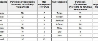
5.1. The following must be clearly marked on the neck, shank or holder of the countersink:
a) trademark of the manufacturer;
b) diameter for countersinks types 2-4 or diameter for countersinks types 1.5-11;
c) countersink cone angle;
d) countersink designation (last four digits);
e) steel grade of the cutting part (on countersinks made of high-speed steel). Notes: 1. On countersinks of types 1-4 with a diameter of 5 to 8 mm and types 5-7 with a diameter of 8 to 12.5 mm, it is allowed to mark only the data specified in subparagraphs a, b, c.
2. Marking on the shanks or holders of countersinks may be applied by electrochemical, chemical or other methods that do not affect the quality of the surface and provided that their geometric shapes are preserved, as well as in the recess for marking.
3. (Deleted, Amendment No. 1).
4. Steel grade R6M5 and R6AM5 may not be marked.
5. Instead of the high-speed steel grade, it is allowed to mark the letters “HS” for steel with a tungsten content up to 3% inclusive, the letters “HSS” for steel with a tungsten content of 6% or more, the letters “HSSCo” for steel containing cobalt, with an indication steel grades on labels.
5.2. The option for internal packaging of countersinks is VU-1 according to GOST 9.014.
5.1, 5.2. (Changed edition, Amendment No. 1, 2).
5.3. Other requirements for packaging, labeling, transportation and storage are in accordance with GOST 18088. (Introduced additionally, Amendment No. 1). Section 6. (Deleted, Amendment No. 1).
Operation and repair of metal countersinks
Before you start working, you need to study the safety rules. To protect yourself from injury, you need to:
- Wear a hat, safety glasses, and gloves.
- If work will be carried out on a machine, be sure to install a protective screen made of transparent plastic.
- Wear closed shoes, clothes with tapered sleeves, from which threads and flaps do not stick out.
- Clear the workplace of foreign objects.
- Check the integrity of wires and moving equipment elements.
Do not handle rotating cartridges while wearing gloves.
The countersinking procedure is similar to drilling. After starting the engine, the working part is slowly immersed in a pre-drilled hole. Processing is carried out slowly.
When countersinking, allowances must be observed. It is important to select the diameter of the selected tool so that after processing it matches the size of the hole being processed.
For repairs and sharpening, it is better to contact a workshop. You won’t be able to fix it yourself; this requires professional equipment and practical skills.
TOOLING - BEARING CENTER
There are three main methods for making a helical flute in a drill: ground profile, milled profile and screw rolled. In production, the cheapest method is screw rolling, which consequently sacrifices quality. This does not bother domestic companies and they massively purchase these drills from China. Moreover, they are made from the cheapest steel 4241 (less than 3% tungsten W) and are marked P6M5. In principle, they are quite suitable for woodworking.
Drill sharpening
If you work with wood, you don't need to sharpen the drill for years. It's a different story with metal drills. They are made of high-speed steel and the hardness of the working surface reaches HRC 62-64. The most common steel grades are P9, P6M5, P18 and P6M5K5. A special place is occupied by carbide drills made of VK8 and VK6M alloys, which are manufactured both monolithic and with brazed plates. A significant number of types of drills also determines different approaches to their sharpening and regrinding.
The type of material being processed also plays an important role, on which the angle of the drill depends. For drilling structural, alloyed and similar steels it is usually 2φ118°, and for softer steels 2φ135°.
When sharpening and regrinding, not only the cutting angle φ must be obtained, but also the rear angles α 8-18° necessary for cutting and the back of the head. This will prevent the rear surface from rubbing against the bottom of the hole. The quality of sharpening is assessed by the axial runout of the edges δ, which depends on the error in the circumferential pitch of the grooves Δ and the eccentricity of the core ω. The non-straightness of the cutting edges should not exceed 2 δ.
The runout can be easily checked with a dial gauge indicator, which is mounted on a stand.
When processing brittle materials, wear occurs along the back surface and corners, and when processing viscous materials, wear occurs along the strip. In addition to wear and tear, polyps can form on the ribbons. The main task is the consolidated placement of the chips formed during the drilling process in the drill flute. Various sharpening methods are used, among which the most common are screw, compound screw and two-plane for drills with brazed carbide plates. To extend the service life of the drill, a sharpening of the jumper is often used, since it essentially does not cut, but scrapes. Reducing the length of the bridge reduces heating and premature chipping of cutting edges.
Sharpening is carried out using abrasive wheels, both straight profile made of normal 25A electrocorundum, and cup-shaped CG wheels. Finishing is carried out with wheels made of green silicon carbide 64C. Sharpening of carbide drills is carried out with diamond discs of disc and cup shape 12A2. Diamond pencils are used to edit circles. When sharpening, it is advisable to use gloves and safety glasses to avoid injury.
When sharpening, do not allow the drill to overheat, as cracks may appear and the carbide plates may peel off. In order to avoid this, it is necessary to periodically cool the drill with liquid. For cooling, you can use ordinary water, but cutting fluid (coolant) is much more effective, which should not be forgotten during the drilling process. Selecting a drill for thread cutting
Rules for using the tool
When using a countersink, work should be carried out using a lathe or drilling machine. It is very important that the chuck is in good condition, otherwise, when the cutter runs out, it will not be possible to obtain a clear cylindrical recess. The rules for using the tool are as follows:
- For each type of work, you need to choose the type of cutting element suitable for this purpose: to form a cone with a recess - a countersink with an oblong body and a guide pin, for small recesses - a regular conical countersink, for hard alloys - a tool with carbide tips.
- The diameter of the cutting element must correspond to the required diameter of the recess. If you machine with a tool with a much larger diameter, this can lead to poor centering of the recess relative to the hole, non-compliance with the cone angle and the exact depth.
- When choosing the rotation speed of the cutter, you must adhere to those speeds that are recommended for this particular tool. Excessive speed leads to overheating of the working part and rapid wear of the cutting edges.
- When working with cast iron or alloys made of solid material, it is necessary to remove heat from the working area; for this, special emulsions must be used.
- The countersink must be precisely centered relative to the middle of the hole.
Areas of application
The areas of application of countersinks include use on machines such as: - lathes; — drilling; — milling; — boring; — turning-turret; — aggregate. In terms of the level of purity, the countersinking procedure, as a technological process, is classified as semi-finish processing. It is usually used before drilling holes in blank elements made of various materials. Carrying out such a technological operation must be performed at low machine speeds. Some types of countersinks are also used for processing and chamfering holes that are located in hard-to-reach places - these are reverse-type tools.
Equipment and tools
The main tool used for countersinking is called a countersink. This is a type of cutter consisting of a working part and a shank. The working part has several cutting edges; the tool is attached to the shank in the equipment chuck. There are conical and cylindrical cutters. The raw material for the manufacture of countersinks is carbon or alloy tool steel.
Conical countersinks are characterized by the angle of inclination of the knife. The most commonly used elements are those with cone angles of 120, 90, 60 and 30 degrees. Cylindrical cutters have teeth at the end. These teeth can be from 8 to 4 pieces. In addition, the cylindrical tool has an element guiding the hole, which is called a pin. Thanks to this element, the cylindrical cutter is always aligned with the hole it is processing.
For countersinking holes, special holders have also been developed into which countersinks are inserted. They may have rotating or non-rotating type limiters.
TECHNICAL REQUIREMENTS
GOST R 53664-2009 high-strength cylindrical and conical bolts for bridge construction. nuts and washers for them. technical specifications
2.1. (Deleted, Amendment No. 2). 2.2. Countersinks must be made from high-speed steel in accordance with GOST 19265. It is allowed to manufacture countersinks from other grades of high-speed steel, ensuring the performance and durability of countersinks are not inferior to countersinks made from high-speed steel in accordance with GOST 19265. By agreement with the consumer, it is allowed to manufacture countersinks from tool alloy steel grade 9ХС according to GOST 5950.
2.3. Countersinks made of high-speed steel with a cylindrical shank with diameters from 8 to 16 mm should be made in one piece, with diameters of 20 and 25 mm - welded. High-speed steel countersinks with a conical shank must be manufactured welded.
The following are not allowed in the welding zone: lack of penetration, ring cracks, surface holes.
It is allowed to manufacture soldered countersinks with cylindrical and conical shanks with diameters from 12.5 to 25 mm.
Brass grade L63 according to GOST 15527 should be used as solder.
2.4. The shanks of welded and brazed countersinks must be made of steel grade 45 according to GOST 1050 or grade 40X according to GOST 4543.
2.5. The hardness of the working part of the countersinks should be:
for countersinks made of high-speed steel with a diameter of up to 3.15 mm - 63 ... 65 HRC3, over 3.15 mm - 63 ... 66 HRC3;
for countersinks made of steel grade 9ХС - 62 ... 65 HRC3.
The hardness of the working part of countersinks made of high-speed steel with a vanadium content of 3% or more and cobalt of 5% or more should be higher by 1-2 HRC3 units.
2.6. The hardness of the feet for countersinks with a conical shank should be 32 ... 47 HRC3.
2.7. The surface of the countersinks should not have cracks or signs of corrosion. Sanded surfaces should not have dents or rough spots. There should be no tarnish on the front and back surfaces, on the surfaces of the ribbons and the shank. Cutting edges must be sharp; debris and chipped areas on cutting edges are not allowed.
(Changed edition, Amendment No. 1, 2).
2.8. The roughness parameters of countersink surfaces according to GOST 2789 should be, microns, no more than:
front and rear surfaces of countersinks types:
1-4……………………………………………………………..Rz 6.3
5-11……………………………………………………………………..DgZ,2
surfaces of chip flutes……………………………….Rz 10
surface of the clamping cylindrical part, cylindrical and conical
shank…………………………………………………………..Ra 0.8
other surfaces……………………………………..Rz 20
2.9. On the back surface of the teeth of countersinks of types 5-11 along the main cutting edges, a ribbon with a width of no more than 0.05 mm is allowed.
2.10. Maximum deviations of countersink dimensions should be no more than:
total length L…………………………………………Б6
diameter of the clamping cylindrical part…………………………b9
cone angles 60° and 75°……………………………………………………….—20′
cone angles 90° and 120°………………………………………………………—G
length of cylindrical shank……………………………..±1 mm
2.11. The runout tolerance of the cutting edges of the countersink part for countersinks of types 1-4 relative to the surface of the clamping part, measured perpendicular to these edges, should be for countersinks with a diameter of:
up to 3.15 mm…………………………………………….0.03 mm
St. 3.15 mm………………………………………………………………0.04 mm
2.12. The runout tolerance of the cutting edges of countersinks of types 5-11 relative to the surface of the shank, measured perpendicular to these edges, should be 0.05 mm.
2.13. The average and established periods of resistance of countersinks must be no less than those indicated in the table. 7 subject to the tests given in Section. 4.
which should not be more than 0.6 mm for countersinks types 1-4 and 0.8 mm for countersinks types 5-11.
| Table 7 |
| 2.14. The criterion for dullness should be considered the achievement of wear on the rear surface, |
What is a countersink, systematization
A cutting tool for metal (countersink) allows you to countersink an opening in a part up to accuracy group 5. It is widely used for semi-finishing parts before mechanical reaming. According to its structure, it is divided into types:
- holistic;
- nozzles;
- tail;
- connected.
Externally, metal-cutting devices look like a simple small drill, but have an increased number of cutting edges. The correct dimensions of the opening of the workpiece being processed is determined by the gauge. The tools are fastened in the unit's chuck with the support of the shank.
To cultivate openings with a diameter of up to 10 cm, attachments with 4 points are used. Their main feature is fastening through a mandrel. The presence of a chamfer on the teeth of the element made it possible to achieve correct adjustment of the cut.
APP (recommended). EXECUTIVE DIMENSIONS OF COUNTERSINKERS
APPENDIX Recommended
mm
| Countersink N 1 | Countersink N 2 | |||
| max. | name | max. | name | |
| 3,0 | 2,875 | 2,850 | 3,050 | 3,025 |
| 3,5 | 3,375 | 3,350 | 3,050 | 3,525 |
| 4,0 | 3,875 | 3,850 | 4,050 | 4,025 |
| 4,5 | 4,375 | 4,350 | 4,550 | 4,525 |
| 5,0 | 4,875 | 4,850 | 5,050 | 5,025 |
| 6,0 | 5,875 | 5,850 | 6,050 | 6,025 |
| 7,0 | 6,815 | 6,780 | 7,060 | 7,030 |
| 8,0 | 7,815 | 7,780 | 8,060 | 8,030 |
| 9,0 | 8,815 | 8,780 | 9,060 | 9,030 |
| 10,0 | 9,815 | 9,780 | 10,060 | 10,030 |
| 11,0 | 10,790 | 10,755 | 11,070 | 11,035 |
| 12,0 | 11,790 | 11,755 | 12,070 | 12,035 |
| 13,0 | 12,790 | 12,755 | 13,070 | 13,035 |
| 14,0 | 13,790 | 13,755 | 14,070 | 14,035 |
| 15,0 | 14,790 | 14,755 | 15,070 | 15,035 |
| 16,0 | 15,790 | 15,755 | 16,070 | 16,035 |
| 17,0 | 16,790 | 16,755 | 17,070 | 17,035 |
| 18,0 | 17,790 | 17,755 | 18,070 | 18,035 |
| 19,0 | 18,755 | 18,710 | 19,085 | 19,040 |
| 20,0 | 19,755 | 19,710 | 20,085 | 20,040 |
| 21,0 | 20,755 | 20,710 | 21,085 | 21,040 |
| 22,0 | 21,755 | 21,710 | 22,085 | 22,040 |
| 23,0 | 22,755 | 22,710 | 23,085 | 23,040 |
| 24,0 | 23,755 | 23,710 | 24,085 | 24,040 |
| 25,0 | 24,755 | 24,710 | 25,085 | 25,040 |
| 26,0 | 25,755 | 25,710 | 26,085 | 26,040 |
| 27,0 | 26,755 | 26,710 | 27,085 | 27,040 |
| 28,0 | 27,755 | 27,710 | 28,085 | 28,040 |
| 30,0 | 29,755 | 29,710 | 30,085 | 30,040 |
| 32,0 | 31,710 | 31,660 | 32,100 | 32,050 |
| 34,0 | 33,710 | 33,660 | 34,100 | 34,050 |
| 35,0 | 34,710 | 34,660 | 35,100 | 35,050 |
| 36,0 | 35,710 | 35,660 | 36,100 | 36,050 |
| 37,0 | 36,710 | 36,660 | 37,100 | 37,050 |
| 38,0 | 37,710 | 37,660 | 38,100 | 38,050 |
| 40,0 | 39,710 | 39,660 | 40,100 | 40,050 |
| 42,0 | 41,710 | 41,660 | 42,100 | 42,050 |
| 44,0 | 43,710 | 43,660 | 44,100 | 44,050 |
| 45,0 | 44,710 | 44,660 | 45,100 | 45,050 |
| 46,0 | 45,710 | 45,660 | 46,100 | 46,050 |
| 47,0 | 46,710 | 46,660 | 47,100 | 47,050 |
| 48,0 | 47,710 | 47,660 | 48,100 | 48,050 |
| 50,0 | 49,710 | 49,660 | 50,100 | 50,050 |
| 52,0 | 51,650 | 51,590 | 52,120 | 52,060 |
| 55,0 | 54,650 | 54,590 | 55,120 | 55,060 |
| 56,0 | 55,650 | 55,590 | 56,120 | 56,060 |
| 58,0 | 57,650 | 57,590 | 58,120 | 58,060 |
| 60,0 | 59,650 | 59,590 | 60,120 | 60,060 |
| 62,0 | 61,650 | 61,590 | 62,120 | 62,060 |
| 63,0 | 62,650 | 62,590 | 63,120 | 63,060 |
| 65,0 | 64,650 | 64,590 | 65,120 | 65,060 |
| 67,0 | 66,650 | 66,590 | 67,120 | 67,060 |
| 70,0 | 69,650 | 69,590 | 70,120 | 70,060 |
| 72,0 | 71,650 | 71,590 | 72,120 | 72,060 |
| 75,0 | 74,650 | 74,590 | 75,120 | 75,060 |
| 80,0 | 79,650 | 79,590 | 80,120 | 80,060 |
The text of the document is verified according to: official publication Countersinks for processing parts made of light alloys. GOST 21579-76 - GOST 21586-76: Sat. GOST. - M.: Standards Publishing House, 1990
Countersink designation in the drawing
In production, countersinking of holes is carried out according to the drawing. The countersink in the drawing is displayed in uppercase and capital Latin letters and Arabic numerals. The meaning of the letters and numbers is as follows:
- d1 – indicates the main diameter of the channel;
- d2 – for countersinking diameter;
- L1 – displays the length of the cylindrical channel;
- L3 is the countersinking depth;
- L4 – indicates the depth of the chamfer;
- j is the size of the central countersinking angle;
- α (alpha) – chamfer angle size.
Basic rules for countersinking processing
Correct countersinking processing requires adherence to a specific technological process, which is developed for a specific part. The technological process itself is built on principles or rules that take into account absolutely any initial conditions: type of metal, hole diameter, shape, configuration, channel length, final countersinking task, type of tool.
The basic rules for processing with a countersink are as follows:
- After casting, stamping or drilling process, the allowance on the side in the hole for countersinking should be 0.5–3 millimeters.
- The type of cutting element must match the type of hole. They can be through, stepped or blind.
- The rotation speed when processing a cutter made of high-speed steel should not differ from the rotation speed of a conventional metal drill.
- The rotation speed of a cutter with carbide cutting edges can be increased two or three times compared to the rotation speed of a conventional countersink.
- For high precision machining of holes produced by casting or stamping, having a deep channel, they are first passed with a cutter to the depth of half the working fluid of the countersink and with a diameter equal to the diameter of the cutting edge.
When using countersinks made of high-speed steel, a substance is supplied into the channel being processed for lubrication and cooling.
TEST METHODS
4.1. Tests of countersinks must be carried out on centering, lathe or drilling machines using chucks and collets that meet the accuracy standards established for them.
4.2. Countersinks must be tested on samples made of steel grades 45 or 50 according to GOST 1050, hardness HB 179...197 using pre-drilled holes corresponding to GOST 14034 and GOST 12876 for countersinks of types 6 and 10.
4.3. Resistance tests are carried out on countersinks with a diameter of 8 mm for type 1; 6.3 mm for types 2-4, 20 mm for types 5-11. It is allowed to additionally test countersinks of other standard sizes from those regulated by the standard.
4.1-4.3. (Changed edition, Amendment No. 1).
4.3.1. Tests should be carried out at the modes indicated in Table 8.
Table 8
| Countersink type | Diameter, mm | Feed, mm/rev | Speed, m/min | |
| external countersink | center hole | |||
| 1 | 5,0 | — | 0,05 | 14 |
| 8,0 | 0,08 | 16 | ||
| 2-4 | — | 0,8 | 0,01 | 8 |
| 1,0 | 10 | |||
| 1,25 | ||||
| 1,6 | 0,02 | |||
| 2,0 | 12 | |||
| 2,5 | 0,03 | |||
| 3,15 | ||||
| 2-4 | — | 4,0 | 0,04 | 14 |
| 5,0 | 0,05 | |||
| 6,3 | 0,06 | |||
| 8,0 | 0,08 | 16 | ||
| 5-11 | 8,0 | — | 0,06 | 12 |
| 10,0 | ||||
| 12,5 | 14 | |||
| 16,0 | 0,08 | |||
| 20,0 | 16 | |||
| 25,0 | 0,10 | |||
| 31,5 | ||||
| 40,0 | 18 | |||
| 50,0 | 0,12 | |||
| 63,0 | ||||
| 80,0 | 0,14 |
Notes:
1. The rotation speed for countersinks of types 1-4 is determined by the diameter of the machined hole, and for countersinks of types 5-11 - by the largest diameter of the countersinked hole. For countersinks of types 7 and 11, the hole must be pre-countersunked.
2. When testing countersinks made of 9ХС steel, the cutting speed is assumed to be equal to 0.6 of the cutting speed of countersinks made of high-speed steel. (Introduced additionally, Amendment No. 1).
4.4. Acceptance values of the average and established durability periods should not be less than those indicated in Table 9.
Table 9
| Countersink type | Countersink outer diameter, mm | Acceptance values of durability periods, min | |
| average | installed | ||
| 1 | 5,0 | 23 | 9 |
| 8,0 | |||
| 2 | 5,0 | 23 | 9 |
| 6,3; 8,0; 10,0 | 34 | 14 | |
| 12,5; 16,0 | 68 | 27 | |
| 3 | 5,0; 6,3 | 23 | 9 |
| 7,1; 8,0; 10,0 | 34 | 14 | |
| 12,5; 14,0; 16,0; 20,0; 25,0 | 68 | 27 | |
| 4 | 6,3 | 23 | 9 |
| 8,0 | 34 | 14 | |
| 5, 8 and 9 | 8,0 | 23 | 9 |
| 10,0 | 28 | 11 | |
| 12,5 | 34 | 14 | |
| 16,0 | 34 | 14 | |
| 20,0 | 57 | 23 | |
| 25,0 | 79 | 32 | |
| 31,5 | 113 | 45 | |
| 40,0 | 147 | 59 | |
| 50,0 | 181 | 72 | |
| 63,0 | 204 | 81 | |
| 80,0 | 204 | 81 | |
| 6, 7, 10 and 11 | 8,0 | 11 | 5 |
| 10,0 | 14 | 5,4 | |
| 12,5 | 17 | 7 | |
| 16,0 | 17 | 7 | |
| 20,0 | 23 | 9 | |
| 25,0 | 34 | 14 | |
| 31,5 | 51 | 20 | |
| 40,0 | 51 | 20 | |
| 50,0 | 68 | 27 | |
| 63,0 | 90 | 36 | |
| 80,0 | 90 | 36 |
4.5. When testing for performance, three holes must be machined with each working end of the countersink for the length of the conical part of the countersink, and for countersinks of types 2-4 - five holes.
4.6. A 5% solution of emulsol in water with a flow rate of at least 5 l/min should be used as a cutting fluid.
4.7. After performance testing, the cutting edges of the countersinks should be free of dents and chipping and should be suitable for further work.
4.4-4.7. (Changed edition, Rev. 1, 2).
4.8. Appearance control is carried out visually.
4.9. Control of countersink parameters is carried out by means of control, the error of which should not be more than: when measuring linear dimensions - the values specified in GOST 8.051; when measuring angles - 35% of the tolerance values for the angle being tested; when monitoring the shape and location of surfaces - 25% of the tolerance values for the parameter being tested.
4.10. The hardness of countersinks is measured according to GOST 9013.
4.11. The surface roughness parameters of countersinks should be checked by comparison with roughness samples in accordance with GOST 9378 or with standard tools having values of surface roughness parameters not exceeding those specified in clause 2.8. Comparison is carried out visually using a magnifying glass 2-4 in accordance with GOST 25706.
4.8-4.11. (Introduced additionally, Amendment No. 1).
Design features
The all-metal countersink tool in the drawing has several main structural parts:
- Working body. The main part of the element, which essentially performs the countersinking operation. It contains cutting edges - there can be a different number of them. There is also a base - a cylindrical part where the incisors converge from the top of the cone.
- The shank is an important part of the element. With its help, the cutter is fixed in the equipment chuck. The shanks are also different: in some the body is shaped like a cylinder, in others it looks like a truncated cone.
- There is a small isthmus between the shank and the working area - this is also a countersink element. The isthmus is the weakest part of the instrument. It has a smaller diameter than the shank and working head. Its purpose is to act as a fuse in case the cutter jams in the workpiece; in this case, it should simply burst and prevent larger-scale destruction.
In addition to all-metal countersinks, there are tools with insertable blades. In this case, the blade material is made of a stronger grade of steel than the base of the element. This design allows you to have a high-quality cutter, but at the same time, the cost will not exceed that of popular products.
Another cutter design has high-strength tipped cutting edges. These cutting elements are good for processing hard alloys or cast iron.
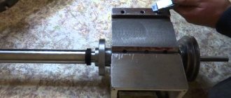
DIY countersink
A wood countersink is a fairly popular tool on the market, but your store may not have it, but it is still a necessary thing. And if you already have all the necessary components, then you can build a countersink machine with your own hands. The equipment will be far from the professional units that are used in enterprises and factories, but it has advantages over expensive analogues. In order to build a machine you need the following things:
Powerful drill;
The base of the machine is made of wood or metal;
Sturdy corner tripod, also made of wood or iron;
Homemade stand for extra stability;
Spring mechanism for reverse movement of the drill.
These are the basic components that can be used to assemble a machine that will provide stable and accurate machining. Strength, weight, durability, and construction price will depend on the choice of material. There is no point in saving much in this matter, because countersinking is a precise process, and any deviation or defect can lead to poor results.
To create the attachment itself, use a self-tapping screw or drill, which you need to trim, adding new blades. This design has many advantages:
Created at home from existing components;
Does not require large investments;
Can be customized at any time for individual configurations;
Ability to carry out a variety of types of stationary work with a drill;
But even taking into account all the advantages, the artisanal countersink has a number of disadvantages. Some disadvantages are minor and can be easily corrected, but they exist and are mostly associated with miscalculations during modeling and incorrect assembly of the structure. These are the disadvantages:
An error during sharpening can lead to an overestimated diameter;
Rapid wear of nozzles;
Any defect or error leads to loss of quality;
Therefore, you need to pay attention to calculating the design and testing the machine before its direct use. And if everything is done correctly, then such a machine will be an excellent assistant in working with wooden parts. And if desired, the equipment can be converted for iron parts
And if desired, the equipment can be converted for iron parts.
Video that describes the sequential process of creating a countersink for wood