Comparative characteristics
First of all, when choosing a caliper, you will need to decide on its dimensions and the parts that will be measured.
For small surfaces not exceeding 13 cm, it is recommended to use a tool up to 150 mm. This is the most common model, it is convenient and easy to use and store. For parts 20–30 cm in size, it is better to use a larger caliper, but the control is quite complicated, especially if the part is on the machine. When determining the size of a tool, its accuracy and measuring step are also important. When turning, it is necessary to select equipment of increased accuracy, class 0.01 mm, with possible errors of up to 0.02 mm.
For working with wood, lower precision is suitable, since the raw material is soft and can expand from moisture. For carpentry work, models will be cheaper, and their choice is much wider.
Additional functions are an important part of electronic calipers. Modern models help measure in mm and inches, but fractional data does not show everything. Other functions include:
- ability to connect to a computer - models of this type will help simplify the calculations of a large number of parts when you need to draw up a specific measurement report. The connection can be wired or wireless; after synchronization, a report is created in electronic form,
- Automatically turning off or turning on the device allows you to increase battery life.
The last factor that is taken into account when choosing is the material of the product. The service life and protective characteristics depend on this parameter. It is recommended to buy a stainless steel caliper, which does not corrode and is not afraid of stress. For turning work, it is better to take equipment that is protected from oil. Outdoor work requires models with protection from dust, moisture, class IP54 and higher.
Simplicity and reliability of calipers
Before proceeding to a detailed examination of the design of a caliper and working with it, it is worth noting several important and common requirements for various types of measuring instruments. This will help to more accurately determine the place and area of use of the caliper in the measurement system:
- The error of a measuring instrument is approximately half the value of its scale division.
- The tolerance on the measured value determines the choice of measuring instrument.
- The highest division value of the measuring tool should be approximately 3 times less than the tolerance.
The standard division values for the most common types of tools ШЦ-I and ШЦ-II are 0.1 and 0.05 mm. Therefore, if the production of a part includes a control operation, these calipers can control dimensions with a tolerance of at least 0.3 and 0.15 mm, respectively.
Device and types
The tool consists of the following main parts:
- A rod with single-sided or double-sided jaws and a printed main scale with a division value of 1 mm. Both designs are designed to measure both external and internal dimensions of parts. The jaws are usually made of carbide material.
- A carriage that can be moved along the rod with response jaws and a vernier scale. A depth gauge rod may be attached to the carriage.
The most common are calipers of the ShTs-I and ShTs-II types with measurement intervals of 0−150 and 0−250 mm, respectively. The ShTs-III model is designed for measuring parts with dimensions up to 500 mm, the reach of the jaws is up to 300 mm. Based on the type of readings taken, there are mechanical, indicator and digital calipers.
The rod scale allows you to determine the entire part of the measured size. The measurement of the fractional part and its accuracy is determined by the presence and value of the division of the vernier scale.
Working with a scale
The zero size corresponds to the combined divisions 0 of both scales. The value of 10 on the vernier scale corresponds to the value of 39 on the main scale, and it includes 20 divisions.
Division 10 of the vernier corresponds to the main value 39, we can say that it is shifted to the left by 1.00 mm from division 40. According to the rules of the geometric proportion of the mark 9.5, the vernier is shifted by 0.95 mm from the mark 38, then accordingly and proportionally: mark 9 ,0 - 0.90 mm from mark 36, the average mark 5.0 of the vernier is shifted to the left 0.5 mm from mark 20, and finally, mark 0.5 is shifted to the left by 0.05 mm from mark 2.
When the carriage is shifted to the right in the range from 0 to 1 mm by a fraction of 0.05 mm, the marks of both scales will be consistently combined: if the gap between the jaws is 0.05 mm, the mark of 0.05 coincides with the mark of 2 mm, the gap of 0.10 mm is 1 .00 of the vernier is combined with a 4 mm main mark, a gap of 1.00 mm - 10 of the vernier is combined with a 40 mark.
For example, you need to measure several wires with a diameter of up to 1 mm. The wire diameter is 0.05 mm, if the 0.05 division of the vernier most accurately coincides with one of the divisions of the main scale. If the marks 0 and 10 of the vernier scale exactly coincide with the marks of the main scale, the wire has a diameter of 1.00 mm.
Measurements during the design and manufacture of threaded connections
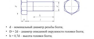
The “bolt-nut” type connection is one of the most common in mechanics. When designing and manufacturing structures, the problem of how to measure a bolt with a caliper is often difficult.
Before starting work, it is worth remembering that the main dimensions of a bolt/nut are the length of the product and the diameter of the thread. A standard bolt of any design does not require such measurements. It’s a different matter when the bolt is made at home, or you need to measure the fastener without dismantling the connection. The following situations are possible here:
- Between the head and the opposite end of the rod there is a plane or part/plate, the dimensions of which do not allow the insertion of the measuring jaws of a caliper. In this case, using the main measuring scale and a depth gauge (sometimes called a “Columbic”), the height of the head, the thickness of the washer (if any), the thickness of the intermediate element and the height of the part protruding from the opposite side of the joint are determined. The obtained result is added up, and then, according to the tables of correspondence between the lengths of the rod and the “turnkey” dimensions that the bolt has, the standard size of the fastener is determined.
- The diameter of the thread on the bolt is unknown. Before taking measurements, it is worth remembering that for rod parts, the diameter of the external thread is determined by the diameter of its protrusions, and not the recesses. Therefore, by setting the required size on the external scale of the caliper, you can easily find out the desired value of the thread being measured. It should be equal to one of the standard values of the first (or, in extreme cases, the second) series of preferred numbers. Accuracy will increase significantly if the area being measured is thoroughly cleaned of dirt and grease. If the result for some reason does not fit into the standard, the depth of the thread is determined using a depth gauge. By subtracting twice the value of the parameter from the total value, you can check whether a used bolt with a cut part of the thread profile was used. This product should be replaced.
- The bolt being measured is completely “recessed” into the nut, and disconnection of the structure is undesirable. Using the external scale of the caliper, you should set the dimensions of the head - “turnkey” and the diameter of the circle of the protrusions. Then, using measurement tables, determine the standard size of the fastener. In the same way, measurements are made of other standardized fastening parts - studs, screws, etc. The exception is nuts. Here you will have to use internal sponges. In some instruments, it is necessary to add the thickness of the jaws themselves to the result obtained (it is indicated on the bar).
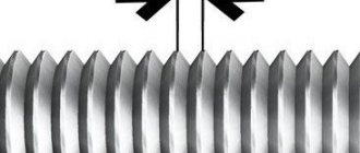
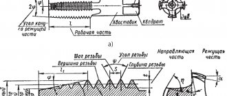
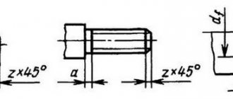
- How to measure thread pitch with a caliper? To do this, the bolt will have to be unscrewed. First, the height of the rod is determined using a depth gauge, and then the number of threads on it is counted. The difference will give the value of the tangent of the thread angle, i.e., the ratio of the unknown pitch to the outer diameter. The latter is already known, so finding out the thread pitch is no longer difficult. You can determine the thread pitch by directly measuring the distance between adjacent vertices, but this will be accurate enough only for fasteners that are completely free of contamination.
Bolt thread pitch definitions:
Place a straight edge on the threaded part of the bolt. If its millimeter divisions coincide with the tops of the threads, then you undoubtedly have a pitch of 1 mm. If not, then count the number of turns n on a certain segment of length L. Do not take the first thread into account, since the counting comes from it, and it is zero.
| Number of turns per 2 cm | Thread pitch, mm |
| 9 | 2,5 |
| 11 | 2,0 |
| 12 | 1,75 |
| 14 | 1,5 |
| 17 | 1,25 |
| 21 | 1,0 |
| 26 | 0,8 |
| 29 | 0,7 |
Divide the length of the taken segment in millimeters by the number of turns and get the pitch P.
P= L/(n-1) = 20 mm / (17-1) turns = 1.25 mm
It is important to take into account that the larger the threaded section you take for measurements, the smaller the error will be. A more accurate result can be obtained using a caliper by aligning the extreme tips of the threads with the tip of the tool jaws.
The thread pitch is closely related to the diameter of the bolted connection. Data on the correspondence of these two parameters are summarized in the table. We measure the outer diameter of the bolt, in our example we get 10 mm. From the table we see that the M10 bolt can have a thread pitch: 1.5 (main)
,
1.25 (fine)
,
1.0 (fine)
or
0.75 (superfine)
. The number obtained by calculation must exactly (or almost exactly) match the reference value. In our case, a metric thread of the second row with a fine pitch of 1.25 mm. Bolt designation: M10x1.25.
Types of calipers and technical characteristics
The classification of such measuring instruments is carried out according to several parameters - the method of taking readings, the type of scale, the location of the jaws. All these differences are reflected in the markings of the device.
For different types of calipers, the following types of scales can be used to take measurement readings:
- vernier scale;
- scale located on the dial;
- using a scoreboard with a digital indicator.
According to their design, calipers are divided into the following types:
- Single-sided tools made of carbide steel and marked ШЦТ.
- Mechanical models with one- or two-sided arrangement of jaws, marked as ШЦ-I, ШЦ-II, ШЦ-III, measurements on which can be taken using a vernier scale.
- A device equipped with a circular scale is marked ShIK or ShTsK and allows for more accurate measurements than devices with a vernier scale. The dial scale shows fractional readings, while the bar itself shows whole numbers.
- The latest generation electronic caliper with a digital display showing the distance between the internal surfaces of the jaws is marked SCC and can work in symbiosis with a PC. This is the best device that allows you to quickly, without unnecessary calculations, see measurement data, which is carried out with high accuracy up to 0.01 mm.
The ShTs-II tool differs from the ShTs-I model in that it has an additional frame equipped with a locking screw and connected to the main frame. A fixed additional frame allows you to bring the ends of the jaws in for more accurate measurement of the internal dimensions of the holes.
The ShTs-III device differs from the ShTs-II model in that it does not have one pair of upper marking jaws. Used for measuring large parts.
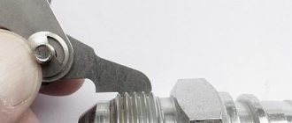
How to determine threads with a caliper or ruler
To determine the type of thread on the fitting, a caliper is needed.
How to correctly take measurements using a caliper is shown in the figure below. Measurements must be made accurate to tenths of a millimeter.
| Outer diameter, mm | Inner diameter, mm | Thread pitch, threads per inch | Thread pitch | BSP | Metrics | Inch UNF | Inch NPT |
| 9,3-9,7 | 8,5-8,9 | 28 | 1/8″ | ||||
| 9,3-9,7 | 8,5-8,9 | 27 | 1/8″ | ||||
| 9,7-9,9 | 8,2-8,6 | 1,5 | M10x1.5 | ||||
| 10,9-11,1 | 9,7-10,0 | 20 | 7/16″-20 | ||||
| 11,6-11,9 | 10,2-10,6 | 1,5 | M12x1.5 | ||||
| 12,4-12,7 | 11,3-11,6 | 1/2″-20 | |||||
| 12,9-13,1 | 11,4-11,9 | 19 | 1/4″ | ||||
| 12,9-13,1 | 11,4-11,9 | 18 | 1/4″ | ||||
| 13,6-13,9 | 12,2-12,6 | 1,5 | M14x1.5 | ||||
| 14,0-14,3 | 12,7-13,0 | 18 | 9/16″-18 | ||||
| 15,6-15,9 | 14,2-14,6 | 1,5 | M16x1.5 | ||||
| 16,3-16,6 | 14,9-15,4 | 19 | 3/8″ | ||||
| 16,3-16,6 | 14,9-15,4 | 18 | 3/8″ | ||||
| 17,6-17,9 | 16,2-16,6 | 1,5 | M18x1.5 | ||||
| 18,7-19,0 | 17,3-17,6 | 16 | 3/4″-16 | ||||
| 19,6-19,9 | 18,2-18,6 | 1,5 | M20x1.5 | ||||
| 20,5-20,9 | 18,6-19,0 | 14 | 1/2″ | ||||
| 20,7-21,1 | 18,3-18,7 | 14 | 1/2″ | ||||
| 21,6-21,9 | 20,2-20,6 | 1,5 | M22x1.5 | ||||
| 22,0-22,2 | 20,2-20,5 | 14 | 7/8″-14 | ||||
| 22,6-22,9 | 20,6-21,0 | 14 | 5/8″ | ||||
| 23,6-23,9 | 22,2-22,6 | 1,5 | M24x1.5 | ||||
| 25,6-25,9 | 24,2-24,6 | 1,5 | M26x1.5 | ||||
| 26,1-26,4 | 24,1-24,5 | 14 | 3/4″ | ||||
| 26,3-26,7 | 23,7-24,1 | 14 | 3/4″ | ||||
| 26;6-26,9 | 24,3-24,7 | 12 | 1,1/16″-12 | ||||
| 29,6-29,9 | 27,4-27,8 | 2 | M30x2 | ||||
| 29,8-30,1 | 27,6-27,9 | 12 | 1,3/16″-12 | ||||
| 29,6-29,9 | 28,2-28,6 | 1,5 | M30x1.5 | ||||
| 32,6-32,9 | 30,5-30,9 | 2 | M33x2 | ||||
| 33,0-33,2 | 30,3-30,8 | 11 | 1″ | ||||
| 33,0-33,3 | 30,8-31,2 | 12 | 1,5/16″-12 | ||||
| 32,9-33,4 | 30,3-30,8 | 11,5 | 1″ | ||||
| 35,6-35,9 | 33,4-33,8 | 2 | M36x2 | ||||
| 37,6-37,9 | 36,2-36,6 | 1,5 | M38x1.5 | ||||
| 40,9-41,2 | 38,7-39,1 | 12 | 1,5/8″-12 | ||||
| 41,6-41,9 | 39,4-39,8 | 2 | M42x2 | ||||
| 41,5-41,9 | 39,0-39,5 | 11 | 1,1/4″ | ||||
| 41,4-42,0 | 39,2-39,6 | 11,5 | 1,1/4″ | ||||
| 44,6-44,9 | 42,4-42,8 | 2 | M45x2 | ||||
| 44,6-44,9 | 43,2-43,6 | 1,5 | M45x1.5 | ||||
| 47,3-47,6 | 45,1-45,5 | 12 | 1,7/8″-12 | ||||
| 47,4-47,8 | 44,8-45,3 | 11 | 1,1/2″ | ||||
| 47,3-47,9 | 45,1-45,5 | 11,5 | 1,1/2″ | ||||
| 51,6-51,9 | 49,4-49,6 | 2 | M52x2 | ||||
| 51,6-51,9 | 50,2-50,6 | 1,5 | M52x1.5 | ||||
| 59,4-59,8 | 56,5-56,8 | 11 | 2″ | ||||
| 59,9-60,2 | 56,4-56,7 | 11,5 | 2″ | ||||
| 63,3-63,6 | 61,3-61,8 | 12 | 2,1/2″-12 |
CONTACTS
st. B. Okruzhnaya 4-b, s. Petropavlovskaya Borshchagovka, Kiev-Svyatoshinsky district, Kiev region, 08130, Ukraine
Postal address: PO Box 70, Kyiv-162, 03162
information:
+38
branches
- Kyiv
- Sumy
- Krivoy Rog
- Kyiv
- Gorishni Plavni
- Vinnitsa
- Berdichev
- Kherson
- Khmelnitsky
- Pervomaisk
- Kyiv
- Lviv
SUPPLIERS
Manufacturers of components, materials and units
- Manuli Hydraulics
- Rexroth
- Dana Brevini Group
- Meccanica Borroni
- Tecsoflex
see everyone
How to measure a piston with a caliper
The question of how to measure the piston with a caliper remains unresolved. First, let's find out why it is necessary to measure this part. The piston is one of the most important parts of internal combustion engines. During operation, the piston heats up to extremely high temperatures, and when heated, metals tend to increase thermal expansion. This increase is minor, but it plays a very important role.
You need to measure the diameter of the piston with a caliper in order to find out its conical part. The conical zone is the part that is located from the finger to the top. It is this part that must have a conical design, which will allow the piston to work effectively in the internal combustion engine system. If the piston has the same diameter along its entire length, then it should be bored. The gap between the piston and the cylinder walls should be no more than 0.045-0.05 mm. The taper of the piston should be 0.3 mm.
It is almost impossible to measure such indicators using a caliper, since high accuracy and low error are required. For such purposes, a micrometer is used, which differs from a caliper in that it allows you to measure dimensions with high accuracy. If it is necessary to measure the length, depth of the groove and other parameters, then a caliper is used for this. How to measure a piston using a micrometer is shown in the video below.
https://youtube.com/watch?v=JBgePO4gRpw%3F
How does a digital caliper work?
There are three modifications of calipers, they are divided according to the method of taking dimensions.
- The simplest vernier models can be used for home needs. Integer values are taken from the bar, the fractions are determined by the vernier - these are the basic rules for how to use a vernier caliper.
- The mechanical measuring principle is used in dial models. Through a gear transmission, fractions of a millimeter are transferred from the rod scale to the dial, and whole values are taken from the rod.
- The most convenient and accurate is the digital option, where all results are obtained from the display screen. The electronic part itself can be customized, making it even more convenient to use.
To understand how to use it, you need to understand how a digital caliper works. The work is based on a digital capacitive vernier: inside the device there is a capacitive matrix, several plates, the main ones being the stator and the slider. When taking calculations, they are displayed on the display, the stator is located on a mechanical ruler, and the rotor is located under the display itself.
https://youtube.com/watch?v=7CsvxNz6K50%250D
Linear dimensions measurements
How to measure linear dimensions using a caliper? It all depends on the material of the part/workpiece. For rigid elements, the product is pressed tightly against some support plate, after which the measurement is taken with the external measuring jaws of the tool. You must first determine the suitability of the existing type of caliper for use. For example, the main measuring scale on the rod should be less than 25...30 mm longer than the part (taking into account the own width of the jaws). When using a depth gauge, this value is even smaller, since the length of the frame should also be taken into account (for the most common tools 0-150 mm and an accuracy of 0.05 to 0.1 mm, this parameter is taken to be at least 50 mm).
Read also: Threading machines
How to measure the cross-section of a wire with a caliper? Non-metallic products are flexible, and therefore significantly distort the result obtained in the usual way. Therefore, a rigid steel part (screw, nail, piece of rod) should be inserted into the cambric, and then the cross-sectional diameter of the wire should be determined using external jaws. Do the same if you need to find out the internal size of the wire.
Wire diameter measurement
The question - how to measure a chain with a caliper - is often asked by cyclists, since chain wear, defined as the distance between its adjacent links, makes it possible to decide whether to replace the product. The outer jaws are set at a distance of 119 mm and inserted into the link, after which they are stretched to the sides until further increase in size is impossible (to facilitate the work, the chain can be pre-loaded with a tensile force). The deviation from the original size will show actual wear, which must then be compared with the maximum allowable.
If you find an error, please select a piece of text and press Ctrl+Enter.
Vernier calipers belong to the class of universal high-precision measuring instruments. This device is designed to determine the external and internal dimensions of small parts, hole depths and other parameters. Knowing how to measure with a caliper, you can easily establish the linear values of any objects, including threaded connections on hardware.
Diameter measurements
How to measure diameter with calipers? There are parts with a constant and variable cross-section along the length. The latter include, in particular, reinforcing bars. How to measure the diameter of reinforcement with a caliper? It all depends on the reinforcement profile, which can be:
- ring;
- sickle-shaped;
- mixed.
Measuring the inner diameter with a caliper
It is easiest to measure such reinforcement parameters in the second case. First, use external measuring jaws to determine the height of the protrusions of the profile, and then use a depth gauge to determine the size along the depression. Measurements must be taken in two mutually perpendicular directions, since reinforcement, and even not produced at specialized enterprises, often has an oval cross-section. After this, the most suitable value is found using tables of standard reinforcing profiles (special accuracy is not required here). How to measure the diameter of reinforcement with a caliper if it has a different type of profile? Here, instead of the diameter of the protrusions, the diameter of the protruding part of the crescent-shaped notches is determined, and then proceed in the same way as in the previous case.
Measuring the outer diameter of a pipe
When measuring the internal dimensions of pipes, use the internal measuring scale of the tool. How to measure the thickness of a pipe with a caliper, especially if the gap is small? It is enough to calculate the difference between the outer and inner diameters and divide the result by two.
Measurements during the design and manufacture of threaded connections
The “bolt-nut” type connection is one of the most common in mechanics. When designing and manufacturing structures, the problem of how to measure a bolt with a caliper is often difficult.
Before starting work, it is worth remembering that the main dimensions of a bolt/nut are the length of the product and the diameter of the thread. A standard bolt of any design does not require such measurements. It’s a different matter when the bolt is made at home, or you need to measure the fastener without dismantling the connection. The following situations are possible here:
- Between the head and the opposite end of the rod there is a plane or part/plate, the dimensions of which do not allow the insertion of the measuring jaws of a caliper. In this case, using the main measuring scale and a depth gauge (sometimes called a “Columbic”), the height of the head, the thickness of the washer (if any), the thickness of the intermediate element and the height of the part protruding from the opposite side of the joint are determined. The obtained result is added up, and then, according to the tables of correspondence between the lengths of the rod and the “turnkey” dimensions that the bolt has, the standard size of the fastener is determined.
Measuring internal threads and imprinting threads
Thread pitch measurement
Measuring with a thread gauge
The best option for correctly measuring threads is to use a thread gauge. This is a special tool for measuring cutting pitch. The thread gauge is a body to which probes are attached in the form of thin plates with a comb. The shape of the comb exactly matches the standard thread with a certain pitch.
The following types of thread gauges are distinguished:
- Metric. Allows you to measure the thread pitch of a bolt, nut or other part with a metric thread with a diameter from 1 to 600 mm. The tool has up to 20 measuring plates and allows you to determine thread pitch from 0.4 mm to 7 mm. Indicated by the marking “M60” on the body.
- Inch. Used to measure inch threads, which are usually cut on pipes and pipeline parts, and are also sometimes used on fasteners. The pitch of an inch thread is determined by the number of threads per inch of length of the threaded part of the part. The thread gauge is equipped with 17 measuring plates with a number of turns from 4 to 28. The “D55” marking is used to mark the tool.
- Universal. Equipped with measuring plates for metric and inch cutting. Such thread gauges are widely used in workshops where it is necessary to simultaneously work with parts with both metric and inch threads.
Before determining the pitch, you need to measure the diameter of the thread with a caliper. This is necessary because the pitch range may depend on the diameter.
The process of measuring pitch using a thread gauge is extremely simple. Visually suitable thread gauge plates are applied to the thread being measured. Using the selection method, a plate is selected whose comb will exactly match the thread being measured. Its pitch will correspond to the standard value indicated on the marking of the measuring plate.
The easiest way to measure external threads is this way. If you need to determine the pitch of the internal thread, then the measurement location must be illuminated in order to accurately determine the tight fit of the thread gauge plate comb.
When measuring the pitch of a metric thread, the desired parameter is obtained in millimeters. If it is necessary to measure the pitch of an inch thread, then its value is obtained in the number of turns per inch.
Vernier caliper device
The main elements of the tool with names are already shown above, but let's take a closer look. This video successfully shows various models and examples of working with them, and also explains what a caliper consists of.
Mechanical models
They differ in that all measurements are made by manually moving the elements and visually determining the readings using the measuring markings.
Depending on the design of the product, the scale may have different lengths (see table above) and, accordingly, the permissible measurement range. These numbers don't match. So, if the length of the marking of the tool rod is 14.5 cm (the digital designations may not be completely marked, as can be seen in the photo), then it can be used to measure a part or hole with a width/diameter/depth of up to 13...13.3 cm.
The accuracy of measurements is determined by the marking of the vernier - up to tenths or hundredths of a millimeter. The same number is indicated on the device itself in the form of a marking like this.
Each manufacturer, especially foreign ones, can give their own markings, so when purchasing a product it is better to check with the seller exactly where this marking is affixed and what it means.
When working with products manufactured in countries where the inch measurement system (English) is adopted, a caliper with an inch vernier marking in addition to the millimeter one may be more convenient.
Please note: in this case, there are inch markings not only on the vernier, but also on the rod, and the measurement accuracy is indicated separately for both measurement systems
Electronic (digital) calipers
In these devices, moving the jaws along the rod is also done manually, but the alignment of the scales and the issuance of measurements is carried out automatically, by tracking the movement of the vernier along magnetic marks.
The accuracy of measurements depends on the frequency of mark placement and tracking accuracy.
This is what the “inside” of a digital caliper might look like.
(Bottom photo shown at high magnification)
This is what the main part of the electronic device looks like up close.
Here, too, as you can see, there is a switch from the metric to the inch measurement system.
It is worth noting that when working with such a model, it is more convenient to look at the readings on the display; it is more difficult to properly track the position of the slider relative to the bar markings than in a mechanical device.
Marking calipers
They should be separated into a separate group, since with the help of this tool you can not only measure the required element of the product, but also transfer the size to another part. Their feature is the rigid fixation of the tool elements relative to each other after taking measurements - only in this case can the part be marked with the required accuracy.
This photo shows the SCRTI 200 - 0.1 model with needles. Let us recall that the letter “T” in the marking means the manufacture of sponges or, in this case, needles, from hard alloy.
Model ShTsKT-I-150 - 0.02 with a circular vernier, used mainly for measurements, but also for marking.
Model ShTsR 150 - 0.1 with a circular sponge breeding system.
Digital instrument ShTsTsRT 300 - 0.01 with circular jaw opening and accuracy up to hundredths of a millimeter.
How to work?
In order to operate a caliper correctly, you need to understand how to read the readings. Everything here is a little more complicated than with a simple ruler. The fact is that the instrument has two scales. The first (main) is the millimeter one. It provides initial measurement data. The second (also vernier) will help you measure parts with high accuracy. Even fractions of a millimeter can be recognized on it.
Vernier is 0.1 mm, so correct measurement can give a very accurate result. But each model of calipers may have a different pitch (one division). As a rule, the stride length is indicated slightly to the left on the scale itself.
Also, the vernier scale can be different in length. For some models, it reaches 2 cm (20 mm) from the main measuring scale, while for others it can be about 4 cm. The longer the length, the more accurate the secondary scale will give readings. Basically, modern calipers measure with an accuracy of up to 5 hundredths of a millimeter (0.05 mm), older devices have an accuracy of only one tenth of a millimeter (0.1 mm), which is half as much.
The caliper has two pairs of jaws: upper and lower. Some have only one, but these are already highly specialized types of devices. The outer width and height are measured with the upper pair of jaws. The bottom one takes measurements of the diameter and internal width of the part. The internal grooves must be pressed tightly inside the element so that there is no play and the diameter measurement is very accurate.
These jaws can be moved apart over a fairly large distance, so they can be used to measure the diameter, length, width and height of a pipe, large bearing, large parts and other types of spare parts. But the main advantage of a caliper is that it can determine the parameters of very small or thin objects. For example, you can use it to measure the cross-section of a cable, determine the width of a wire, nail, nut, bolt thread pitch, and much more.
When doing a lot of turning or metalworking work, a caliper is always used because of its convenience and versatility. But this device can also be used at a construction site.
Also, in addition to a pair of sponges, some models also have a depth gauge. With its help, you can easily measure depth, even for small parts. This device extends along with the measuring and vernier scale. The depth gauge line is very thin and fits comfortably into the back of the caliper. In order to measure the depth, simply lower this device all the way into the part (while placing it so that the part itself has support) and secure it on top using a clamping screw. After this, using the measuring scale, you can calculate the depth in the same way that length, height and other quantities are measured.
If you don't know what drill you used to make a particular hole, just measure the diameter. In general, a caliper can answer many questions, and after some work with the part being measured, you will be able to study it completely. The caliper may come with an instruction manual, so you can read it before using it for the first time.
If the caliper is corroded, treat it with a special rust remover. Just make sure that this product does not corrode the metal, because this can lead to the fact that divisions and steps on the measuring and vernier scales will not be visible.
There are also electronic types of calipers, but they must be handled more carefully. First of all, do not allow water or other liquids to come into contact with the device. A short circuit may occur in the electronic display, and you will not be able to find out the exact data.
Also, you should not measure anything that runs on electricity. This may throw off the scoreboard, and the results after measurement will be incorrect. Before starting work, check the device and press the ON button to turn on the caliper. After you have taken the readings and you need to take the measurement again, press the zero position button. The principle of switching on is approximately the same as that of a non-programmable calculator: after each operation, the value must be reset.
Also, in the electronic version of the caliper, it is necessary to change the power supply. To do this, open the protective cover and replace the battery. Also remember about polarity. If the battery is working, but the display still does not work, check whether the battery is inserted correctly.
Measurements of the dimensions of the pattern on the protectors
How to measure tire tread if you need to assess the degree of wear? A depth gauge will help, which takes measurements along the entire tire tread. It should be taken into account that wear is almost always uneven, and the number of measurements should be at least 3...5, and on evenly distributed areas of the tire tread for assessment. Before measurements, the tire should be thoroughly cleaned of dirt, dust and fragments of small stones stuck inside.
Sometimes you need to solve the problem of how to measure the tire tread with a caliper to determine the degree of uniformity of wear. This establishes the wear of the tread tires not only in depth, but also along the radius of transition from the circle of protrusions to the circle of depressions. They do this. The depth of the pattern on the new tire tread is measured, and then the linear size of the visually changed zone on the used part. The difference will determine the degree of wear and help you make the right decision about replacing the wheel.
All measurements are made with a depth gauge, which must be installed strictly perpendicular to the tire tread.
Measuring tread wear with a Columbian
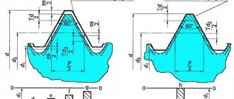
Metric thread
The main difference between a thread of this type and similar ones is that only in a metric thread the profile angle is 60° (there are also threads with an angle of 55° and 47°).
Metric threads are used everywhere, including in metric fasteners. Due to its widespread use, it was necessary to create an impressive number of varieties in order to adapt this universal thread to different situations.
Measuring with a thread gauge
The best option for correctly measuring threads is to use a thread gauge. This is a special tool for measuring cutting pitch. The thread gauge is a body to which probes are attached in the form of thin plates with a comb. The shape of the comb exactly matches the standard thread with a certain pitch.
The following types of thread gauges are distinguished:
- Metric. Allows you to measure the thread pitch of a bolt, nut or other part with a metric thread with a diameter from 1 to 600 mm. The tool has up to 20 measuring plates and allows you to determine thread pitch from 0.4 mm to 7 mm. Indicated by the marking “M60” on the body.
- Inch. Used to measure inch threads, which are usually cut on pipes and pipeline parts, and are also sometimes used on fasteners. The pitch of an inch thread is determined by the number of threads per inch of length of the threaded part of the part. The thread gauge is equipped with 17 measuring plates with a number of turns from 4 to 28. The “D55” marking is used to mark the tool.
- Universal. Equipped with measuring plates for metric and inch cutting. Such thread gauges are widely used in workshops where it is necessary to simultaneously work with parts with both metric and inch threads.
Before determining the pitch, you need to measure the diameter of the thread with a caliper. This is necessary because the pitch range may depend on the diameter.
The process of measuring pitch using a thread gauge is extremely simple. Visually suitable thread gauge plates are applied to the thread being measured. Using the selection method, a plate is selected whose comb will exactly match the thread being measured. Its pitch will correspond to the standard value indicated on the marking of the measuring plate.
The easiest way to measure external threads is this way. If you need to determine the pitch of the internal thread, then the measurement location must be illuminated in order to accurately determine the tight fit of the thread gauge plate comb.
When measuring the pitch of a metric thread, the desired parameter is obtained in millimeters. If it is necessary to measure the pitch of an inch thread, then its value is obtained in the number of turns per inch.
Measuring tool Vernier caliper, instructions for use.
A caliper is a high-precision instrument used to measure external and internal linear dimensions, depths of holes and grooves.
It is not possible to measure the diameter of a drill or hole or the dimensions of other small parts with sufficient accuracy using a ruler. In such cases, you need to use a caliper, which allows you to measure linear dimensions with an accuracy of 0.1 mm. Using a caliper, you can measure the thickness of sheet metal, the internal and external diameters of a steel pipe, the diameter of a drilled hole, its depth and other measurements.
There are several subtypes of different calipers depending on the size, design features and principle of operation.
This is the simplest and most popular model of the device, which is widely used in industrial production. It is called “Columbus” after the name of the manufacturer’s company, which produced the instrument during wartime (Columbus). At one time, calipers were supplied en masse to the industry of the USSR. Hence the established “everyday” word “Columbus” or “Colombic”.
The device can measure internal and external dimensions and depth. The measurement interval is from 0 to 150 mm. The measurement accuracy reaches 0.02 mm.
This digital measuring tool model has a similar design to the classic caliper. Measurement interval 0-150 mm. One of its advantages is higher measurement accuracy due to the presence of a digital indicator.
The convenience of using such a digital device is that the indicator can be reset to zero at any measurement point. You can also easily switch from metric to inch with just one button.
Measuring thread pitch without a thread gauge
For metric fasteners, thread pitch is used instead of TPI. Distance is also measured in millimeters.
To determine the thread pitch, a caliper is used to calculate the distance from the top of one thread to the next. The formula used for this is M2 x 4 x 5 mm, where M2 refers to the diameter of the bolt (in millimeters), i.e. 4 is the thread pitch in millimeters, which means it is equal to 4 mm between each thread peak, and 5M is bolt length.
Thread pitch is used to measure the threads of a bolt or nut to ensure they fit together. If the threads of the bolt and nut are different, they either do not grip or wear out the threads, resulting in an unusable connection.
Small threaded fasteners have a denser helical structure and are usually less pronounced. A coarse threaded connection has larger and deeper threads. This means that if the threads are slightly damaged, it may still work. Most standard metric fasteners have fine and coarse threads. Each of them can be identified using or thread pitch.
In the US and UK, fasteners typically have thread sizes ranging from ¼ to 20 inches and ¼ to 28 inches. To determine which of these threads is coarse and which is fine, you simply need to take the TPI number (20 and 28) and compare them.
Don't forget that coarse thread means the thread is larger, so smaller ones will be able to fit within an inch. So 20 means it's a coarse thread and 28 means it's a fine thread. TPI and thread pitch will vary depending on the diameter of the fastener, so the value will not always be 20 and 28.
For metric fasteners, similar parameters would be represented as M8 x 1.25 or M8 x 1. For thread pitch, the distance between two points is the second number, meaning the higher the number, the fewer threads. It follows that M8 x 1.25 is a coarse thread, and M8 x 1 is a fine thread.
§ 17. Measuring the dimensions of parts using a caliper
When manufacturing parts from thin sheet metal and wire, you can use the simplest control and measuring tools: a ruler, a bench square, etc. To measure and control parts with greater accuracy, calipers are used. They are designed to measure the external and internal dimensions of parts and the depth of holes, grooves, and grooves. Vernier calipers come in different types and differ in the range and accuracy of measurement.
Figure 63 shows the ShTs-1 caliper with measurement limits from 0 to 125 mm and accuracy of 0.1 mm. It consists of a rod 1 having a scale of 6 with millimeter divisions. A movable frame 4 moves along the rod, which can be secured in the desired position with a clamping screw 3. A depth gauge 5 is attached to the frame.
Rice. 63. Caliper ШЦ-1: 1 — rod; 2 - jaws for internal measurements: 3 - clamping screw for fixing the frame; 4 — movable frame; 5 — depth gauge; 6 — rod scale; 7 - vernier; 8 — sponges for external measurements; 9 - measured parts
The lower jaws 8 are used to measure external dimensions, the upper 2 are used to measure internal dimensions. A depth gauge measures the depth of grooves and holes.
How is it possible to measure tenths of a millimeter if the caliper scale has millimeter divisions? For this purpose, an auxiliary scale called vernier 7 is used. The length of the vernier is 19 mm. The vernier is divided into 10 equal parts, therefore, the price of each division is 1.9 mm.
With the jaws closed, the zero strokes of the scale of the rod and the vernier coincide (Fig. 64), and the tenth stroke of the vernier is combined with the nineteenth stroke of the millimeter scale.
Rice. 64. Bar scale and vernier
Please note that the first line of the vernier does not reach the second line of the rod scale by exactly 0.1 mm (2 – 1.9 = 0.1). This allows measurements to be taken with an accuracy of up to 0.1 mm
When measuring with a caliper, an integer number of millimeters is counted on the millimeter scale of the rod to the zero line of the vernier. Tenths of a millimeter - on the vernier scale from the zero mark to the vernier stroke that coincides with any stroke of the millimeter scale (Fig. 65).
Rice. 65. Examples of measuring with a caliper. The position of the rod and vernier scale when measuring dimensions: a - 0.4 mm; 6 - 6.9 mm; in — 34.3 mm
Remember!
A caliper is an expensive measuring tool that requires careful handling.
Rules for handling vernier calipers
Before starting work, wipe the caliper with a clean cloth to remove grease and dust.
Do not clean the tool with sandpaper or a knife.
Do not place the tool on heating devices.
Only clean parts without burrs, burrs or scratches can be measured.
The jaws of the caliper have sharp points, so you need to be careful when measuring.
Do not allow the caliper jaws to become distorted. Fix their position with a clamping screw.
When reading the readings on the measuring scales, hold the caliper directly in front of your eyes.
In enterprises, calipers are one of the main measuring tools. It is used by workers of various specialties and supervisors of machine tools and plumbing operations. Currently, calipers with digital indicators (battery powered) are increasingly used, allowing parts to be measured with an accuracy of 0.01 mm.
Getting to know the professions
The controller of the technical control department (QCD) is a specialist who is responsible for the quality of manufactured parts at the enterprise. He's keeping an eye on it. so that the manufactured parts exactly correspond to the drawings. This is a very responsible job, since if a defective part that does not correspond to the drawing gets into the product, the product will quickly fail. Quality control inspectors must know the rules for setting up and regulating instrumentation and instruments, methods for checking the quality of surfaces, rules for accepting parts, etc.
Laboratory and practical work No. 17
Measuring the dimensions of parts with a caliper
- In your workbook, complete the sketch of the stepped roller given by the teacher (Fig. 66).
- Measure each bead size with a caliper and record the results in millimeters in a table.
- Put the resulting dimensions on the sketch made in your workbook.
Rice. 66. Sketch of the “stepped roller” part (to paragraphs 1-3)
Testing your knowledge
- What are the main parts of a caliper?
- How many measuring scales does a caliper have?
- What measurements can you take with a caliper?
- How many times is the accuracy of measurement with a caliper greater than the accuracy of measurement with a ruler?
- How do you use a caliper to measure whole and tenths of a millimeter?
How to check a caliper for accuracy?
When asking the question of how to use an old caliper, we remember that correct results can only be obtained from a proven tool
Once a year, professional calipers are checked, and before using even at home, it is better to pay attention to the main possible inaccuracies
The first thing to check is the coincidence of the zero line and the presence of a gap between the shifted jaws. On a flat surface, check the zero line on the depth gauge. It is important that the movable jaw carriage does not move when the caliper is tilted. In the electronic model, much depends on the timely change of the power source. It’s also a good idea to find out the accuracy class of the caliper, since sometimes you need to determine some measurements as reliably as possible. The first type refers to the so-called household calipers, when a reading of 0.1 mm is enough
For more accurate measurements, tools of the second and third types are needed, where the reading value is already 0.05-0.01 mm.
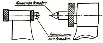
Measuring threads using the three-wire method
The three-wire method is mainly used to control the average thread diameter. The diameter values are determined by placing wires of the same diameter on the cavities of the threaded connections. The size of the resulting structure is measured with a micrometer. The final result of the calculations can be greatly influenced by the profile error. To eliminate this error, it is necessary to place the wires on the profile so that they are connected at the level where the width of the depressions is equivalent to the width of the protrusions. The wires must lie as follows: 1 wire is placed on the depression on the left side, and the other 2 wires are placed on the depressions on the opposite side
It is important that during measurements the part was not deformed and the wires were not bent
In addition, the scope of application of the three-wire method is to control the diameter of trapezoidal threads. Only in this case, the part is checked using three special rollers.