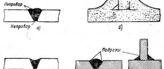
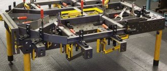
How to make an electromagnetic table from a microwave transformer - for plumbing and welding work
In this review, we want to share with you an interesting idea on how to make an electromagnetic table for welding and plumbing work with your own hands.
This idea (and its implementation) was shared by the author of the YouTube channel Gianni Pirola Fai Da Te.
The advantage of an electromagnetic table is that there is no need to use a vice, clamps or other devices for fixing metal workpieces.
On a homemade electromagnetic table you can both weld workpieces and process them: cut with a grinder, grind, etc.
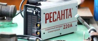
- transformer from a microwave oven (microwave);
- power unit.
General information about the design
The main advantage of magnetic plates is their good workpiece fixation rate, as well as their relatively small size. To complete the machines, two types are used: electromagnetic and magnetic. They have significant design differences.
The stove has a fairly simple operating principle. A magnetic field is created on its surface, which holds metal-containing workpieces on the table surface. This allows you to process not only the outer plane of the materials, but also the end areas. In some cases, it is possible to grind several parts at the same time. Thanks to its magnetic properties, additional equipment or auxiliary devices can be installed on the work surface.
Design features of various types of magnetic plates:
- electromagnetic plate. It consists of a housing, inside of which there are two groups of electromagnetic coils. They are separated by a non-magnetic layer. When electricity is supplied to the installed part, an electromagnetic field is formed, which fixes the workpiece. The disadvantage of this design is the lack of clutch in the event of a power outage. Therefore, it is recommended to install a machine deactivation relay when such a situation occurs;
- magnetic plate. Structurally, it resembles an electromagnetic model. It also contains two groups of magnets that differ in polarity. Blocks of non-magnetic material are installed on the working surface of the stove. In their normal position, they prevent the emergence of a magnetic field. With the help of a mechanical device, they are shifted, as a result of which the workpiece is securely fixed on the table.
The mechanical magnetic plate has a high degree of reliability, but to turn it on/off you need to turn the lever. This affects the speed of changing the positions of parts, and as a result, productivity. Therefore, electromagnetic models are most often used for mass production, and mechanical ones for more precise processing.
In addition to horizontally oriented grinding plates, a device for cross-drilling rollers can be used. Magnets are located along the workpiece, which makes it possible to process cylindrical parts of complex shapes.
DIY magnetic table
Tools for grinding flat surfaces
When grinding, parts can be secured directly to the machine table using clamping bars. However, such fastening is used in cases where the parts cannot be fixed to a magnetic plate or other devices.
Pattern vices (Fig. 10.9a) differ from conventional machine ones in manufacturing precision and the ability to turn. The fixed jaw of the vice is integral with the base 1. The body has grooves for the passage of the movable jaw 2, which is moved by a screw 3. The base of the body has threaded holes for attaching the vice to various devices. All vise planes are machined at an angle of 90°. The pressed-in cylindrical measuring pin 4 is used to measure inclined planes.
Article on the topic: DIY desk for two children
Rice. 10.9. Pattern vice (a) and electromagnetic plate (b)
Electromagnetic plates . The design of the electromagnetic plate (Fig. 10.9b) is based on the following principle. If a wire is wound around an iron core (Fig. 10.10a) and a direct current is passed through it, the core will be magnetized. If you now bring a steel object to one of the ends of the core, it will be strongly attracted to the core. After the current in the winding stops, the magnetic action of the core will also stop.
You can bend such a core in the form of a horseshoe (Fig. 10.10b) and also pass current through its winding. In this case, the magnet will be even stronger. By combining horseshoe-shaped magnets into a group, we get an electromagnetic plate.
Rice. 10.10. Diagram of the magnetic action of current (a) and a horseshoe magnet (b)
The magnet poles located on the top of the plate are carefully insulated from its body with non-magnetic alloys (babbitt, zinc), due to which the magnetic forces are not dissipated in the body of the plate, but are directed directly into the body of the part. Only magnetic metals (for example, steel, iron, cast iron) can be attracted to the electromagnetic plate.
Electromagnetic plates are used in various sizes, round and rectangular. Only direct current is suitable for powering them, so machines are installed with devices that convert alternating current into direct current.
Electromagnetic plates provide reliable and quick fastening of the parts to be ground. To maintain the functionality of the plate, it is necessary to protect it from shocks and shocks, and also to ensure that no coolant gets on the windings. Upon completion of work, you should immediately wipe the working surface of the stove dry.
Magnetic plates
In addition to electromagnetic plates, magnetic plates with permanent magnets are used on grinding machines. This type of stove does not require special generators and rectifiers with wiring and distribution devices. However, as a rule, the force of their attraction is weaker than the force of attraction of electromagnetic plates.
Article on the topic: DIY wardrobe forum
The design of a rectangular magnetic plate and its operating principle are shown in Fig. 10.11. Its upper part is made of steel plates 1 with non-magnetic layers 2 between them (Fig. 10.11a). Strong permanent magnets 4 can be moved, closing them either to the iron plates or to the part being fixed. In Fig. 10.11b shows the position of the magnets when fastening parts 5, and in Fig. 10.11c – during their removal or installation. The magnets are switched using handle 3. The lower part of the plate 6 is fixed on the machine table.
Rice. 10.11. Magnetic plate:
a – general view; b – position of the magnets when securing the part; c - the same when installing and removing the part
Segmented grinding wheels for grinding flat surfaces
Surface grinding with solid grinding wheels of large diameter is economically unprofitable due to large waste, increased heat generation and the possibility of breakage during transportation. In addition, if a crack appears or partial destruction of the wheel, it is necessary to replace it entirely and lose a significant amount of usable abrasive material. These inconveniences are eliminated when using wheels made from inserted abrasive segments (Fig. 10.12). If one or more of them breaks, such segments can be easily replaced with new ones.
The insert segments are used until they are almost completely worn out. By releasing 1 clamp, you can remove 2 segments at once. As they wear, the height of the segments decreases, so spacers are placed under them.
Rice. 10.12. Segment grinding
Magnetic plate for convenient sanding of small parts
Hello, dear readers and DIYers! Surely almost every one of you has encountered the need to process small steel workpieces, and knows that even simple grinding of small parts can cause inconvenience.
In this article, the author of the “TOKARKA” channel will tell you how he made a special magnetic plate, with the help of which this process will be much simpler, easier, and most importantly safer.
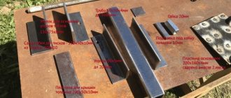
Materials—Aluminum block
- Neodymium magnets
— Two-component acrylic adhesive— Stainless steel sheets— M2 brass screws— Machine oil
Tools used by the author.
— Hacksaw— Milling machine
— Tap
— Dremel — Screwdriver, metal drills — Automatic core
— Construction hair dryer
- Vise, caliper, file, screwdriver.
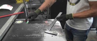
Manufacturing process.
So, a large aluminum block like this is suitable as a body. It has excellent thermal conductivity and will protect the magnets from overheating. The wooden case is not suitable for this homemade product.
Having fixed the block in a vice, the master cuts off a workpiece of suitable size from it.
The surfaces of the block are leveled on a milling machine, although this can also be done with a regular file.
At one end of the workpiece, grooves for magnets are milled. The author will use rectangular magnets. And if it had round magnets, then this procedure would be much simpler, and it would be possible to do without a router.
So, these are the separators we got. He made the central one a little wider than the others; a clamping screw will be screwed into it.
These are neodymium magnets with dimensions of 20X10X5 mm.
They will be glued using epoxy resin; you can also use two-component second glue. Before gluing, it is better to slightly warm up the workpiece so that the epoxy resin fills the cracks better.
The author made a mistake, and when trying to glue in a second magnet, it jumped out and became magnetized to the first one. The gluing process became much easier when he used a plastic card, pressing it against each subsequent magnet.
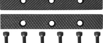
After some time, the resin has polymerized, and the craftsman begins making the protective plate. He will make it from stainless non-magnetic steel. Immediately checks how it passes the magnetic field.
Transfers the markings to the plate with a steel scriber.
In order to accurately cut the strip, he magnetized it to a file and cut it with a Dremel.
Holes are drilled in the plate and body and an M2 thread is cut.
The holes on the plate are countersunk, and it is screwed to the body using brass screws.
In a recent article, the author told how he made such a powerful semi-automatic core. He uses it to mark two steel plates.
Drills holes for M3 bolts in them and the body, and taps them.
The holes in the plates are milled; they must be made elongated.
Next, the surfaces of the body and plates are ground.
Thrust plates are screwed to two side walls; they will be adjustable to the thickness of the workpiece.
This is how you can easily adjust them so that the surface of the part protrudes above the stops.
Without such a magnetic plate, the grinding process was extremely inconvenient; the part could slip off, and the fingers would solemnly fall on the moving abrasive belt. It is strictly forbidden to perform such work while wearing gloves.
So, the device is ready, and now everything has become much more convenient and safer. You can place a block under the device itself.
Here is the result of sanding, everything is fine.
You can also process parts on a grinder with a grinding disc attachment.
A screwdriver with an abrasive disc or a small hand-held sander will also work.
This device can be fixed in a vice and the parts can be processed manually. The pull-off force, provided the workpiece covers all 10 magnets, will be about 40-45 kilograms. And sawdust that gets on the surface can be easily removed with a damp cloth. The master also noticed that the parts do not become magnetized after processing.
I thank the author for a simple but useful device for the workshop! Good mood, good luck, and interesting ideas to everyone!
The author's video can be found here.
Source
Become the author of the site, publish your own articles, descriptions of homemade products and pay for the text. Read more here. (Visited 8 times, 1 visits today)
About the author
Device and principle of operation.
3.1. The plate consists of three main parts: movable and fixed magnetic blocks and a housing. Magnetic blocks are assembled from steel plates, between which ceramic permanent magnets are located. The free space between the steel plates is filled with non-magnetic material.
Rice. Magnetic plate device
3.2. When switched on, poles 2 of the power unit lie on non-magnetic elements 5 of housing 1, directing the entire magnetic flux of magnets 3 through adapter 4 and parts 6. when switched off, poles 2 are located under non-magnetic spacers of the adapter. As a result, the magnetic flux has a new direction.
Article on the topic: DIY chair bed
3.3. The movable magnetic block is located inside the housing and can be moved using an eccentric wolf to the right or left by turning the handle 180˚. In the off position, magnetic circuits with different polarities are combined; there is no non-magnetic flux on the working surface.
Compared to electromagnetic plates and hydraulic or pneumatic devices, they have the following advantages:
- do not require connection to an energy source;
- allow you to achieve higher precision when processing workpieces;
- provide absolute reliability of fastening;
- maintain the main technical parameters during the entire service life at the original level;
- do not require periodic repairs and maintenance
Strengthening a regular magnet
Many questions arise when ordinary magnets cease to perform their direct functions. This often happens due to the fact that household magnets are not such magnets, because, in fact, they are magnetized metal parts that lose their properties over time. It is impossible to enhance the power of such parts or return them to their original properties.
It should be noted that it makes no sense to attach magnets to them, even more powerful ones, since when they are connected with reverse poles, the external field becomes much weaker or is completely neutralized.
This can be checked using an ordinary household mosquito curtain, which should be closed in the middle using magnets. If you attach more powerful magnets on top of weak initial magnets, then as a result the curtain will generally lose its connection properties through attraction, because the opposite poles neutralize each other’s external fields on each side.
How do surface grinding machines work?
The vast majority of parts made of metal undergo a technological operation such as grinding. To perform this with high efficiency and accuracy, surface grinding machines are used.
A rather difficult to manufacture banding machine with excellent functionality
Surface grinding machines of serial models can process both flat and profile parts. The surface processing accuracy that can be achieved using such devices is 0.16 microns. Of course, it is almost impossible to achieve such a result when processing on machines made by yourself. However, even the accuracy that homemade machines allow to obtain is quite sufficient for many metal products.
The load-bearing structural element of the machines of this group (as well as any other equipment) is the bed. Its dimensions directly determine what size parts can be processed on the machine. The most common material for manufacturing beds of surface grinding equipment is cast iron, since this metal, due to its characteristics, perfectly dampens vibrations, which is especially important for devices of this type.
Work table and controls of the 3G71M grinding machine
The structural element of surface grinding machines on which the workpiece is fixed is a work table having a round or rectangular shape. Its dimensions can vary significantly depending on the specific model of surface grinding equipment. The workpieces can be fixed on such a work table due to its magnetized surface or using special clamping elements. During processing, the work table makes reciprocating and circular movements.
Article on the topic: Do-it-yourself heating table for a 3D printer
In mass-produced surface grinding machines, the work tables are driven by a hydraulic system. In self-assembled equipment, mechanical transmissions are used for this.
Grinding a steel workpiece fixed on the working surface of the machine using a magnetic field
Important elements of the design of surface grinding equipment, which ensure the accuracy and smooth movement of the work table, are guides. In addition to high precision manufacturing, the guides must have exceptional strength, since in the process of almost constant movements of the desktop they are subject to active wear.
To achieve high processing accuracy, the guides must ensure accurate, smooth (without jerking) movement of the worktable with minimal friction of the contacting elements. That is why high-strength steel is used for the manufacture of these structural elements, which is hardened after the guides are made from it.
Option for manufacturing guides using angles and bearings
The working tool of a surface grinding machine, which can be a grinding wheel or an abrasive belt, is mounted on the spindle of the headstock. Rotation of the working tool, for which the main electric motor is responsible, can be transmitted through a gearbox or belt drive.
For do-it-yourself surface grinding machines, you can choose a simpler option: select the diameter of the grinding wheel so that it can be mounted directly on the electric motor shaft. This will eliminate the need to use a gear or belt drive.
Technical specifications
Magnetic plates are rarely included as standard equipment in factory equipment. Most often they are purchased separately. Therefore, it is important to know their main technical characteristics, which must correspond to the parameters of a specific machine model.
The determining parameter is the dimensions. The size of the plate can vary from 10*25 cm to 32*100 cm. Moreover, as the dimensions of the device increase, its weight increases. This directly affects the maximum weight of the workpiece, since the plate is installed on a standard work table.
The main parameters that a magnetic plate should have:
- dimensions and weight. Not only width and length are taken into account, but also height. It may affect the maximum permissible part size;
- specific force of attraction. It must be uniform over the entire installation plane. Typically this parameter ranges from 50 to 120 N/cm²;
- distance between poles. This characteristic determines the minimum size of the workpiece.
During operation, the magnetic plate can change the geometry of the workpiece. Therefore, the process of installing and subsequently removing the part should be as careful as possible. You should also take into account the main disadvantage of electromagnetic models - heating of the surface during activation. This is not only the main reason for device failure, but also affects the properties of the workpiece.
The video shows an example of how a small magnetic plate works:
Magnetic levitation at home
In the 90s of the 20th century, the Levitron toy, based on the influence of a magnetic field, became very popular.
This is a levitating top hovering in the air. A similar toy can be assembled at home to understand the essence of magnetic levitation. How to make Levitron - we will present detailed instructions.
List of materials:
- wooden board;
- a simple pencil;
- insulating tape;
- washers made of plastic or brass;
- cardboard;
- 13 neodymium disk magnets brand N52, size 12*3 mm;
- wide ring magnet with an outer diameter of 20, an inner diameter of 10 mm, brand N42.
Article on the topic: Table for printing frames with your own hands
Description of the assembly process step by step:
- Making a layout. Initially, the top was assembled on two ceramic ring magnets. In our design we will use standard neodymium magnets. First, let's print out a diagram of the marking holes for installing magnets. Before starting work, check the conformity of the dimensions in the printed diagram and those indicated in the source code. If everything matches, then cut out the layout.
- Preparing the foundation. Attach a paper diagram to the board and mark according to it. Please note that the thickness of the wooden blank must be 6mm or more.
- Transfer of all circuit blocks to the base. Glue the paper carrier to the resulting base. Using a Forstner drill (d=12mm), punch the center of the circles. This will ensure further drilling accuracy.
- We drill holes. Using a Forstner drill (d=12mm), we make holes in the workpiece so that the bottom of the hole extends 3 mm into the top of the block. The magnets should be positioned as close to the top as possible.
- Installation of magnets. When the holes are ready, you have double-checked their dimensions, install the magnets with one pole facing up, for example the south one. To determine the polarity, you can use the marked D68PC-RB magnet. Place the block on a steel plate to make it easier for the magnets to move to the bottom of the holes. Let's take N52 magnets and place them in the holes, one at a time, as deep as possible. If you need to push the magnet through, you can use a wooden dowel.
- How to make a top. Take a pencil 40 mm long with a pointed end. We wrap electrical tape around it to increase the diameter to fit the central part of the ring magnet. Insert the pencil into the magnet so that the south pole is at the bottom, like the pointy part of the pencil. To add weight to the top, use plastic or brass washers: put several on top. To ensure proper operation, it is necessary to determine the acceptable number of washers using the selection method.
- Let's start the system. Cut cardboard or plastic for the platform. Place it on a magnetic base. On the platform, the top begins to spin and gradually rises with the platform until it falls into the magnetic field well.
Article on the topic: How to make a cutting table with your own hands
If everything is done correctly, the top will freeze. Debugging the mechanism may take a long time.
Tips for adjusting the top:
- Try to ensure the base is balanced. Use pieces of cardboard or paper to raise the sides of the base and level it. If it deviates from the center to some side, lift it by placing pieces of paper under it.
- Apply three-point leveling.
- Consider the weight of the top: the device assumes the presence of a magnetic pit - the strength of the magnet in the center is weaker than near the edge. To keep the magnet in the center, you should add weight (when the top flies out) or decrease it (if the top does not rise from the platform).
- Another significant indicator is the height of the platform: a low platform does not allow the top to spin sufficiently. Therefore, you need to place paper or cardboard under it.
- If you have a 3D printer at hand, you can print a toy on it.
Thus, it is possible to make Levitron with your own hands at home. Based on the presented materials, you can design various souvenirs and interior items that can please you and your friends. In addition, you can show all kinds of tricks with magnets and levitation to children.
Application of neodymium magnets
Neodymium magnets are made from an alloy of the rare earth element neodymium with iron and boron.
They are distinguished by their high ability to attract various metal objects, which is 10 times higher than the attractive ability of ferrite analogues. The neodymium magnet was invented in 1983 and has since become very widespread, despite the fact that prices for rare earth metals, and therefore products made from them, are constantly growing, and the fact that its manufacture requires a lot of time and labor .
It is quite difficult to demagnetize it. Natural decay of magnetic properties occurs at a rate of 0.1-2% per 10 years, but shocks and high temperatures can weaken them, which imposes some restrictions on the area of use. Since the product is susceptible to corrosion, it is usually plated with nickel.
With the help of such a magnet weighing just over 600 g, you can hold an item weighing up to 118 kg. Therefore, neodymium magnets are most often small in size. They are made in the form of disks, bars, spheres, rings, rods, cylinders and prisms.
User manual
The magnetic plate should be re-opened and the equipment passport should be examined.
- Place it on the machine table.
- Check that the mounting is correct and start working.
- A workpiece made of ferromagnetic material must be placed on the working surface in the required position and the lever must be rotated 180 degrees. Check the reliability of the fastening.
- Start processing the workpiece.
- Metal shavings generated during operation can be removed with a brush after turning the handle 180 degrees. Then, after cleaning the surface, you need to fix the workpiece again using the handle.
- Upon completion of work, turn the handle and remove the workpiece.
Necessary materials
To make a structure at home, you should prepare in advance:
- a piece of plastic pipe;
- circular pump for water;
- thyristors for creating an inverter - a device that converts direct current into alternating current;
- 2 types of wire: copper and any stainless metal;
- pliers and wire cutters;
- adapters and ball valve.
This kit will help you make a simple magnetic vortex heater for household needs.
Purpose
The effectiveness of this simulator has long been proven by experts. Such tables are intended for the treatment of various diseases of the musculoskeletal system .
Article on the topic: Do-it-yourself multi-touch table
Inversion tables are effective for the following diseases and pathologies:
- moderate postural disorders (initial stage scoliosis);
- chronic spasms in the muscles of the back or neck;
- as a prevention of varicose veins on the legs;
- for training people who lead a sedentary lifestyle;
- chronic stress as relaxation;
- to strengthen the back muscles.
Keep in mind that you shouldn’t expect any special miracles from using an inversion table .
Although it is used for the treatment and prevention of various pathologies, as a separate treatment method, it has little effect. Since the simulator treats existing diseases and does not in any way affect the cause of their formation.
Therefore, exercises on an inversion table must be combined with other treatment methods, for example, lifestyle changes.
You can buy a finished product in a store, or you can make it yourself. If you have little experience in manufacturing and assembling furniture items, you can resort to the second option.
Blitz tips
- The operation of homemade induction heating devices does not always eliminate the spread of electromagnetic radiation harmful to humans, therefore the induction boiler should be installed in a non-residential area and shielded with galvanized steel.
- When working with electricity, it is imperative to follow safety regulations , especially for 220 V AC networks.
- As an experiment , you can make a hob for cooking according to the scheme specified in the article, but it is not recommended to use this device constantly due to the imperfection of the self-made shielding of this device, because of this, the human body may be exposed to harmful electromagnetic radiation that can negatively affect health .
Making a tabletop with lighting from New Year's garland
There is an easier way to make your own table with an infinity effect. In this case, instead of an LED strip, a regular New Year's garland is used. First, a square or rectangular frame is made from bars, then the number of light bulbs on the garland is counted.
After this, marks are placed on the frame in the places where the light bulbs will be located. It is recommended to place them at a distance of about 2 cm from each other. At the next stage of work, holes for light bulbs are drilled in the frame of the future table.
Then light bulbs are inserted into these holes and secured there. Then you need to glue the frame onto the mirror with your own hands, and glue glass with a mirror film on top of the frame.
What is the difference between a homemade and factory vacuum table?
Working equipment created independently allows you to adapt the device to the needs of a specific production process. Do-it-yourself vacuum tables allow you to take into account all the nuances of processing parts related to their size, as well as include all functions - from milling to molding work. A vacuum table for a CNC machine, assembled independently, saves the user money and simplifies further maintenance of the device.
Article on the topic: DIY plywood table
Vacuum tables can significantly improve the efficiency of the production process and improve the quality of manufactured products. This is achieved by creating the powerful clamping force needed to achieve consistent quality. If the CNC machine does not come with a ready-made table, you can make it yourself. This is a simple process, and diagrams and drawings of devices can be found freely available on the Internet.
- November 15, 2020
- 1218
Induction cooker diagram - basic design
An induction cooker is capable of heating metal cookware through induced eddy currents from a high-frequency magnetic field.
The standard circuit of an induction cooker is usually represented by an induction coil and a frequency converter, as well as an electronic control unit equipped with temperature sensors.
Introduction
Induction cookers are relatively new equipment, but already extremely popular among domestic consumers.
A special feature of such stoves is their ability to heat only the bottom of the cookware.
In conventional electric stoves, the burner that is turned on initially heats up.
Before choosing such equipment, it is important to familiarize yourself with the advantages of operation, as well as take into account some of the design disadvantages of an induction cooker.
The main advantages are presented:
- faster heating and cooking process, which takes several times less time than when using a traditional electric stove;
- no burning of food that may fall on the hob during cooking, which is due to the low temperature of the burner;
- reduction in electrical energy consumption due to very rapid heating of the kitchen utensils used;
- ease of use due to the ability to adjust the cooking mode on different stoves.
The advantages also include safety of operation, which is especially important for families with small children, pensioners or people with disabilities.
Induction cooker in the kitchen
Operating disadvantages in such modern equipment are also present and, despite the fact that they are minimal, they should be taken into account when choosing a model:
- turning on induction equipment at full power can create an increased load on the electrical network;
- for cooking on this type of stove, only special kitchen utensils with a ferromagnetic bottom should be used;
- Some models are characterized by the presence of a single high-frequency generator, which adversely affects the power level when all burners are turned on simultaneously;
- The hob surface is fragile, so during the entire period of operation it is necessary to exercise some caution.
As practice shows, the operation of models belonging to the economy class price category is often accompanied by irritating noise and a kind of humming.
It is important to remember that induction cookers are capable of creating fairly high electromagnetic radiation and can have a negative effect on household appliances installed at a short distance.
Induction cooker diagram
In accordance with the heating circuit, the electric current that flows from the electrical network to the coil undergoes a transformation into a magnetic field that generates eddy currents.
As a result of the interaction of the ferromagnetic bottom with the induction current, a circuit is formed, and the resulting thermal energy warms up the kitchenware used and its contents.
The glass-ceramic surface of the stove covers an induction coil with an electric current flowing at a frequency of 50 kHz.
The standard equipment layout is relatively complex, and can have very significant differences depending on the model.
The basis is represented by a generator, a driver using medium-power transistors and an output bipolar transistor, which has an insulated gate and controls the inductor coil.
The operation scheme of an induction cooker is reflected in the maintenance rules and operating features of such equipment, and must also be taken into account when choosing kitchenware, which must be made of special materials with ferromagnetic properties.
Electrical diagram of an induction cooker
The most complex structural element is the electronic control unit, through which it not only turns on, but also regulates the power level of the generator.
Modern models are characterized by the presence of an infrared sensor device that effectively controls the cooking process.
After the cookware is removed from the hob, the stove automatically turns off.
You cannot use copper, glass, ceramic or aluminum cookware, and the surface of an induction cooker can only be cleaned using special products that do not have abrasive effects.
DIY making
The power circuit of a standard induction cooker can vary significantly depending on the design features of the modification, but most often it is presented:
- a ferrite torus, which is placed on the network wire and suppresses common-mode interference;
- standard fuse;
- a capacitor that filters impulse noise that occurs during operation;
- a resistor that is activated after the mains power is turned off;
- a rectifier designed for power ratings and effectively protecting the device from overvoltage;
- wire shunt;
- filtering system for impulse noise;
- a capacitor that allows you to return energy from the oscillatory-inductor circuit to the intermediate part with constant current values;
- a resonant capacitor that provides continuous current after the transistor is blocked;
- an induction device, which is focused on transferring heat from the surface to the bottom of the kitchenware used;
- a transistor that converts direct current into variable indicators;
- a resistor to fix the transistor after disconnection;
- a resistor to suppress high-frequency current indicators;
- rectifier for voltage in the electrical network;
- a current controller that prevents the possible occurrence of an overload;
- collector voltage controller.
Budget models contain only basic structural elements, which affects the functionality of such a device.
Self-manufacturing of a simple induction cooker requires strict adherence to all standards, which will make the operation of such a device completely safe. A significant difficulty in the process of constructing a stove arises at the stage of selecting high-quality material to create the base of the hob.
DIY induction cooker - diagram
Such a material must be distinguished by the ability to correctly conduct electromagnetic radiation, not conduct current, and withstand high temperatures.
Factory-made household cooking equipment, which includes all modern induction cookers, is made using quite expensive ceramics.
It is for this reason that making your own induction hob at home is associated with certain problems in choosing a worthy alternative to a ceramic surface.
Conclusion
Modern household induction cooktops, as a rule, have a standard scheme, according to which installed magnetic coils, in the process of contact with the ferromagnetic bottom of the cookware, provide stable heating of the prepared food.
Such household equipment can be controlled using mechanical switches and touch buttons, which makes operating the induction cooker very convenient.