general description
Drawing machines are special equipment that is used during metal forming. They can be used to obtain different products. The operating principle of drawing mills is quite simple. A workpiece of a certain diameter is pulled through a hole of a smaller diameter. This work is done by rollers. They give the workpiece not only the required diameter, but also the shape.
As a result, the metal stretches and becomes thinner. The cross-section of the product is round or shaped. The profile is highly accurate. Its surface is characterized by high purity. During metal processing, the workpiece may heat up. There is also cold drawing. The second option has several advantages. The finished product is stronger and harder. At the same time, the yield strength of its material increases.
Drawing is of great importance in metalworking. Drawing machines make it possible to produce wire with a diameter of up to 5 microns. Pipes are also produced using similar equipment. Their maximum diameter is 40 cm. The products of this branch of production are widely used in the national economy and industry.
Copper wire casting
When casting copper wire, the average result is a coil of copper wire with a cross-section of 8 mm. Weighing 6 tons and a long wire of approximately 13 km.
In continuous casting of copper wire rod, we can offer the following products:
- Fully synthetic water-miscible cutting fluid
- used for continuous casting of copper rods and coils
- used for lubrication and cooling of rollers
- the product provides excellent corrosion protection
Required product concentration: 1.5% – 3.5%.
This product has the following advantages:
- very long service life of the working emulsion
- reduces various possible production stoppages when continuously casting copper rods or coils
- very high pH stability (possible formation of fungi and bacteria in the emulsion is reduced)
- the product has a low copper absorption rate
- guarantees a clean and shiny wire surface
- maximum production speed
- increases the service life of rollers
- high wear protection
The product is successfully used at the following factories: Aurubis AG (Italy), Deutsche Giessdraht GmbH (Germany), La Farga Lacambra (Spain).
Multiroll Coating is a special wax emulsion to protect the wire surface during continuous casting of wire rod.
- water-miscible agent for protecting wire during continuous casting wire rod from corrosion
- lubricant for the process of winding finished wire onto a reel
- working concentration: approx. 3% – 6%
Peculiarities
Modern drawing equipment has a number of distinctive features. Modern technologies are used in metal processing. Therefore, today's mills are significantly different from the equipment of past decades. First of all, their productivity increases. Modern mills are capable of producing much more products per unit of time. In this case, the quality of the metal surface will be good.
The new equipment is produced complete with dies, which are characterized by significant resistance to adverse influences and a long service life. Also, modern units provide different degrees of protection. This significantly increases the safety of workers when operating the equipment. The processing accuracy is ensured by modern measuring devices included in the design.
We present to your attention the latest developments from Zeller+Gmelin GMBH & CO. KG.
Multidraw Cu Rod S – based on synthetic components, oil for rough drawing on single-core and multi-core machines. Improved lubricity and cleaning effect compared to Multidraw Cu Rod. Excellent emulsion stability (protection against the formation of fungi and bacteria in the working fluid).
Application: Niehoff (India, rough copper drawing), Berkenhoff (Germany, nickel-plated copper wire).
Multidraw Cu As is a fully synthetic annealing product that exhibits excellent corrosion protection and excellent wire cleanliness.
Functional equipment
Modern wire drawing machines include functional structure and auxiliary equipment. The main part of the structure is responsible for obtaining a certain processing result. Depending on the pulling device, the target area of the mill is determined. The equipment can pull the workpiece in a straight line or wind it onto a drum. In the first case, several types of aggregates are distinguished. They can be track-type, rack-and-pinion, or reciprocating. Also on sale are units with a hydraulic mechanism for drawing the workpiece, and chain drawing machines.
Also on sale is equipment with the function of winding the processed material onto a drum.
On equipment that involves drawing the workpiece in a straight line, rods, pipes, and other similar products are produced. They don't go into riots.
Wire winding technology is used for wire drawing. She may have a special profile. Also, pipes with a minimum diameter are made on such machines.
The presented equipment can be of the following types:
- single drawing (the workpiece is processed once);
- multiple with sliding function;
- multiple with reverse tension;
- multiple without sliding function.
For each type of finished product, the most suitable production method is selected. During production, various metals and alloys are used. The production technology of the product depends on their type. The procedure includes several sequential steps.
Auxiliary equipment
A drawing mill for the production of copper wire, steel pipes or other products necessarily includes a number of auxiliary mechanisms. It is intended to ensure the normal flow of the production process. The category of auxiliary equipment includes unwinders, lubrication equipment, and rewinders. This category of mechanisms also includes devices for sharpening wire, packing coils, and cutting workpieces. In some cases, the material passing through the main equipment requires processing by welding.
In addition to drawing equipment, the equipment may include a drum. The movement is carried out using an electric motor and gearbox. The design of a particular type of machine may differ depending on what material will be processed on it. Equipment for steel has a number of differences from units for non-ferrous metals. However, modern manufacturers produce equipment that is very similar, regardless of the type of metal.
It should be noted that its functionality depends on what material is processed on the machine. Non-ferrous metals are softer than steel. Therefore, the equipment that pulls them has a sliding function. In this case, it is possible to reduce losses due to friction.
Descaling Information
It is necessary to carefully prepare the surface for further processing. Then the result of the drawing process will be much better. To remove scale, modern production uses the following technologies:
- Electrochemical method.
- Mechanical method.
- Chemical option. For example, when an emulsion is used to draw copper wire.
The machining technique is the most common when creating carbon steel workpieces. From an economic point of view, this solution is most in demand. And the procedure itself is performed without additional complications.
First, the wire is laid between the rollers of a special structure, then it is periodically bent in different planes. Finally, metal from wire rod and other variants is cleaned using special brushes.
The chemical method of getting rid of scale will require a serious investment of money. In this case, hydrochloric or sulfuric acid is used. And for the employees themselves, the operation is associated with increased danger. Therefore, such processes are used only when other options are not available for one reason or another.
Only those who have undergone special training are allowed to access the equipment and the work itself. Chemical options for the procedure will become indispensable if scale needs to be removed from stainless, acid-resistant, high-alloy steel grades. This is a great option for those who are concerned about how to protect the cable from abrasion while drawing.
Electrochemical cleaning involves electrolytic etching. The technology is divided into cathode and anode varieties. The effectiveness and safety of the second option is higher. In this case, the role of the anode is played by the workpiece being cleaned. The cathode becomes copper, iron or lead.
Cathodic etching poses a great danger due to the fact that it actively releases hydrogen into the atmosphere. Scale separation is practically uncontrolled. Because of this, so-called “etching fragility” is formed. The design does not change its original properties.
The workpiece must be thoroughly washed after scale has been removed from it using a chemical method. Otherwise, the design will not get rid of problematic elements:
- iron salts;
- mud;
- sludge;
- remnants of etching elements;
- acid solution.
These components will simply dry out if not treated immediately after the operation is completed. First, the structure is washed in cold water, then the pressure is applied to cold water. The pressure value with annealing is approximately 700 Pa.
Video: wire drawing in Germany.
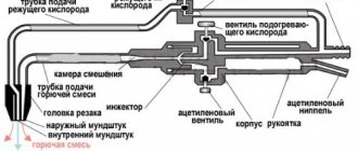
Principle of operation
It is necessary to consider in detail the principle of operation of the drawing mill. The material is fed into the unit from the receiving compartment basket. It passes through a series of roller devices. They direct the movement of the workpiece. Thanks to this action, the material is fed to the carriage roller. This is a compensating type device. After this, the workpiece goes to the drawing mill.
The presence of a compensating carriage in the system is extremely important. This helps prevent material breakage. Such a nuisance could not have been avoided by a sudden stop or braking of the line. The operation of the carriage is quite simple. If the equipment stops abruptly for some reason, this device will continue to rotate the rollers for some time. This allows you to dispense some more material.
The compensating type carriage carries out an upward movement at this time. This allows a certain amount of material to be released. It enters the drawing device. In this case, breaking the workpiece becomes impossible.
Next, the material enters the lower double drum. The reversible roller ensures that the material is carried higher. Here the upper drum receives it. If provided for by the mechanism, the finished product is wound onto the rod and stored here. It is from here that the material is supplied when the mill stops, if it stops abruptly.
If necessary, after drawing, the products are straightened. It is given the necessary configuration. All work is provided by an electric motor.
Annealing copper wire
Continuous annealing is almost always used to recrystallize the wire. After annealing, the wire passes through a low concentrated extinguishing emulsion. The entire line of Multidraw emulsions for drawing copper wire, suitable as an additive to annealing water, with a concentration of 0.5% - 1.5%.
After this emulsion, a thin layer of film remains for annealing, which protects the wire from tarnishing and promotes winding of the wire.
Copper wire drawing with annealing. Z&G Annealing Products
Multidraw CU GWZ is a special emulsion for continuous annealing of copper wire. The product guarantees excellent protection of the wire from the influence of weather conditions, as well as from corrosion for a longer period of time, even for “wet” wire. This emulsion prevents tarnishing of the wire and is suitable for regular and tinned copper wire of all diameters.
Application: Nexans (Germany), ALCABE (Spain).
Manufacturers
Today, the market for special equipment offers a huge selection of drawing equipment. It is distinguished by functionality, performance and quality. In our country, equipment most often purchased is Russian, Chinese and European.
It is important to contact trusted suppliers. They will provide the necessary documentation for such devices. In this case, the equipment will have a warranty. Manufacturers of drawing mills from Europe stand out in this area. They produce the most modern, innovative equipment. It provides many additional functions and modes. This can be either single mills or entire production lines. The quality of the finished product in this case will be the highest. This ensures that the products are the most competitive.
Among European manufacturers of drawing mills, equipment made in Germany and Switzerland is in great demand. Depending on the type of equipment, the minimum cost of the units is 1.5 million rubles. The most famous manufacturer from Germany in our country is the company Sket. Swiss-made equipment is no less popular. It is supplied to our country by the ENCE company.
For those enterprises that have a limited budget for updating fixed assets, it is possible to modernize technical equipment using drawing mills from China. A huge amount of such equipment is produced in this country. The minimum cost is from 1 million rubles.
Domestic manufacturers also supply similar units to the market. The cost of their products is comparable to Chinese ones. But the quality of mills assembled in Russia is higher. Also, some industries buy equipment that has been used. The price of such units starts from 50 thousand rubles. However, in this case you should not count on long-term operation of the equipment and high quality of the finished product.
Test 1 Option 6
Draw a phase diagram for the case of limited solubility of components in solid form. Identify the structural constituents in each area of this diagram and describe the structure of typical alloys of various compositions found in this system. In these alloys, in the solid state, the components dissolve in each other to form solid solutions α (B in A) and β (A in B), between which the eutectic (α + β) is formed. Single-phase areas in the diagram: 1) liquid L – above the liquidus line DCE; 2) TV. solution α – region 0DFK0; 3) TV. solution β – NGE-100-N region.
Figure 1 – Diagram of states of alloys with limited solubility. The lines at the top of the diagram indicate the formation of crystals of α and β solid solutions. However, unlike the previous diagram, the maximum content of component B in α is limited: it cannot be more than M% B (at point F). Likewise, the limiting A content in β cannot be more than (100-N)% A (at point G). That is, in this case, when the components dissolve in each other, so-called limited solid solutions α and β are formed. In general, as the temperature decreases after the solubility limit is reached (i.e., below the FCG level), the limiting content of the dissolved component in the solid solution may change. This dependence of the solubility limit on the temperature of the solid solution α is shown by the FK line, and for β by the GN line. It can be seen that with decreasing temperature the possible content of B in α decreases (from M% B to K% B at 0ºC). Therefore, when alloys containing from K% B to M% B are cooled below the FK line, the excess part of component B will be released from them in the form of crystals of secondary βII (proven by the rule of segments), and in the KFMK region the alloys will have a phase composition α+ βII. In the special case shown by the GN line, the solubility limit of A in β is independent of temperature and the crystals of the β solid solution formed on the GE line will cool to room temperature without any internal changes. In the middle part of the diagram, the alloys crystallize to form a eutectic on the FCG line. The eutectic contains C/% B and crystallizes according to the reaction: Leut–>eut(α+β). In hypoeutectic alloys of this region, in addition to the eutectic, crystals (α + βII) will be present in the final structure of the alloy, and in hypereutectic alloys, β crystals will be present. Structural components of the alloys: 1) α crystals – 0DFK0 region; 2) β crystals – NGE-100-N region; 3) eutectic crystals (α+β) – line СС/.
Drawing of copper wire is carried out in several transitions. In some cases, the wire breaks at the last transitions. Explain the reason for the rupture and indicate how to prevent it.
Drawing of copper wire is associated with plastic deformation of the metal. As a result of plastic deformation, the crystal lattice is distorted, the metal grains are deformed and acquire a certain orientation. In a metal, shear during plastic deformation occurs as a result of the movement of dislocations throughout the crystal. However, plastic deformation causes the appearance and accumulation of new dislocations in the metal. The accumulation of dislocations in a deformed metal complicates and inhibits their movement along the crystal, which in turn causes resistance to deformation on the part of the metal, i.e. hardening. At the same time, the ductility of the metal decreases. As a result, when the metal is drawn, its destruction may occur. Heating of the deformed metal (for copper up to 400°C) leads to an increase in the mobility of atoms, and among the elongated grains there is intensive nucleation and growth of new equilibrium stress-free grains. New grains grow at the expense of old, elongated ones, until they collide with each other and until the elongated grains completely disappear. When heated, upon reaching the temperature at which recrystallization begins, the tensile strength and especially the yield strength sharply decrease, and the ductility increases. Thus, to prevent destruction when drawing copper wire, interoperational heat treatment is used - recrystallization annealing.
Draw a phase diagram of iron - iron carbide, indicate the structural components in all areas of the diagram, describe the transformations and construct a cooling curve (using the phase rule) for an alloy containing 0.5% C. What is the structure of this alloy at room temperature and what is such an alloy called ?
Primary crystallization of alloys of the iron-carbon system begins upon reaching temperatures corresponding to the ABCD line (liquidus line) and ends at temperatures forming the AHJECF line (solidus line). When alloys crystallize along the AB line, crystals of a solid solution of carbon in α-iron (δ-solution) are released from a liquid solution. The crystallization process of alloys with a carbon content of up to 0.1% ends along the AN line with the formation of an α (δ) solid solution. A peritectic transformation occurs on the HJB line, as a result of which a solid solution of carbon in γ-iron, i.e., austenite, is formed. The process of primary crystallization of steels ends along the AHJE line. At temperatures corresponding to the BC line, austenite crystallizes from the liquid solution. In alloys containing from 4.3% to 6.67% carbon, at temperatures corresponding to the CD line, crystals of primary cementite begin to precipitate. Cementite that crystallizes from the liquid phase is called primary. At point C at a temperature of 1147°C and a carbon concentration in a liquid solution of 4.3%, a eutectic is formed, which is called ledeburite. The eutectic transformation with the formation of ledeburite can be written by the formula ЖР4.3Л[А2.14+Ц6.67]. The process of primary crystallization of cast iron ends along the ECF line with the formation of ledeburite. Thus, the structure of cast irons below 1147°C will be: hypoeutectic - austenite + ledeburite, eutectic - ledeburite and hypereutectic - cementite (primary) + ledeburite. Transformations occurring in the solid state are called secondary crystallization. They are associated with the transition of γ-iron to α-iron upon cooling and the decomposition of austenite. The GS line corresponds to the temperatures at which the transformation of austenite into ferrite begins. Below the GS line, the alloys consist of ferrite and austenite. The ES line shows the temperature at which cementite begins to separate from austenite due to a decrease in the solubility of carbon in austenite with decreasing temperature. Cementite released from austenite is called secondary cementite. At point S at a temperature of 727°C and a carbon concentration in austenite of 0.8%, a eutectoid mixture consisting of ferrite and cementite, called pearlite, is formed. Pearlite is obtained as a result of the simultaneous precipitation of ferrite and cementite particles from austenite. The process of transformation of austenite into pearlite can be written by the formula A0.8P[F0.03+Ts6.67]. The PQ line indicates a decrease in the solubility of carbon in ferrite upon cooling and the release of cementite, which is called tertiary cementite. Consequently, alloys containing less than 0.008% carbon (point Q) are single-phase and have a pure ferrite structure, and alloys containing carbon from 0.008 to 0.03% have a ferrite + tertiary cementite structure and are called technical iron. Hypoeutectoid steels at temperatures below 727ºC have a ferrite + pearlite structure, and hypereutectoid steels have pearlite + secondary cementite in the form of a network along the grain boundaries. In hypoeutectic cast irons in the temperature range 1147–727ºС, upon cooling, secondary cementite is released from austenite due to a decrease in carbon solubility (ES line). Upon reaching a temperature of 727ºС (PSK line), austenite is depleted in carbon to 0.8% (point S), turning into pearlite. Thus, after final cooling, the structure of hypoeutectic cast irons consists of pearlite, secondary cementite and converted ledeburite (perlite + cementite). The structure of eutectic cast irons at temperatures below 727ºС consists of transformed ledeburite. Hypereutectic cast iron at temperatures below 727ºС consists of converted ledeburite and primary cementite.
Figure 2: a-diagram of iron-cementite, b-cooling curve for an alloy containing 0.5% carbon The phase rule establishes the relationship between the number of degrees of freedom, the number of components and the number of phases and is expressed by the equation: C = K + 1 – Ф, where C is the number of degrees of freedom of the system; K – number of components forming the system; 1 – number of external factors (we consider only temperature as an external factor, since pressure, except for very high pressure, has little effect on the phase equilibrium of alloys in solid and liquid states); Ф – number of phases in equilibrium. An alloy of iron and carbon containing 0.5% C is called hypoeutectoid steel. Its structure at room temperature is Ferrite + Pearlite.
Draw a diagram of the isothermal transformation of austenite for U8 steel. Draw on it the curve of the isothermal treatment mode, which ensures a hardness of 200 HB. Indicate what this mode is called and what structure is obtained in this case. An isothermal treatment sufficient to obtain hardness HB = 200 for U8 steel is isothermal annealing (Figure 3). The structure after annealing is coarse-plate pearlite. During isothermal annealing, U8 steel is heated to a temperature 30-50°C above the Ac1 point (Ac1 = 730°C) and after holding it is cooled to a temperature of 650-680°C. The structure after annealing is coarse-plate pearlite.
The pearlite transformation of supercooled austenite occurs at temperatures Ar1 = 500ºC. During the transformation process, a polymorphic y->a transformation and diffusion redistribution of carbon in austenite occurs, which leads to the formation of a ferrite-cementite structure: A->F + Fe3C = Pearlite.
Figure 3 – Diagram of the isothermal transformation of austenite in U8 steel. Austenite, almost uniform in carbon concentration, decomposes with the formation of ferrite and cementite containing 6.67% C, i.e. consists of two phases having different carbon concentrations. The leading, primarily emerging phase in this case is carbide (cementite). Its nuclei, as a rule, form at the boundaries of austenite grains. As a result of the growth of particles of this carbide, the adjacent volume of austenite becomes depleted in carbon, reduces its stability and experiences a polymorphic y->a transformation. In this case, ferrite crystals nucleate at the boundary with cementite, which facilitates this process. The subsequent growth of ferrite plates leads to the enrichment of the surrounding austenite with carbon, which complicates the further development of the y->a transformation. In austenite enriched in this way with carbon, new cementite platelets are born and previously formed ones grow. As a result of these processes of formation and growth of carbide particles, conditions are again created for the emergence of new and growth of existing ferrite crystals (plates). As a result, colonial (joint) growth of ferrite and cementite crystals occurs, forming a pearlite colony.
Using the iron-cementite phase diagram, determine the normalization, annealing and hardening temperatures for U12 steel. Characterize these types of heat treatments and describe the structure and properties of steel after each heat treatment. For hypereutectoid steels, complete annealing with heating above Ast (line ES in the diagram) is not used at all, since with slow cooling after such heating a coarse network of secondary cementite is formed, which worsens the mechanical properties. For hypereutectoid carbon steels, annealing with heating to 740-780°C (for U12 steel up to 750-770°C) and subsequent slow cooling is widely used. After such heating, a large number of undissolved cementite inclusions remain in the austenite, which serve as crystallization centers during the decomposition of austenite during cooling. As a result, the structure of granular pearlite (spherodite) is formed, which is why this annealing is called spheroidizing. Small particles of cementite at an annealing temperature in the range A1–Ast are obtained as a result of division of cementite plates. Steel with a granular pearlite structure has the lowest hardness and is easier to machine. In addition, granular pearlite is the optimal initial structure before hardening. With the initial structure of granular pearlite, there is less tendency to growth of austenitic grains, a wider permissible range of quenching temperatures, less tendency to cracking during quenching, higher strength and toughness of hardened steel (small globules are evenly distributed in the martensite of hardened hypereutectoid steel. At room temperature, U12 steel has a cementite structure and pearlite. Up to temperature Ac1, the original structure is preserved. At temperature Ac1, pearlite transforms into austenite with a carbon content of 0.8%. When heated above the Ac1 point, cementite dissolves in austenite (in accordance with the SE line). An increase in temperature above the Acm point causes growth of austenite grains. Critical points for U12 steel: Ac1 = 730°C; Acm = 820°C. For hardening, hypereutectoid steels are heated 50-70°C above point Ac1. Thus, the heating temperature for hardening is 780-800°C At these temperatures, the steel contains cementite along with austenite.Therefore, after quenching, the structure of hypereutectoid steels will contain martensite with cementite and a small amount of retained austenite. The cooling medium during quenching is industrial oil. Surface hardness after hardening is 62-64 HRC. To relieve stress and stabilize the structure after hardening, the products are subjected to low tempering. Normalization consists of hypereutectoid steel to a temperature above the Acm point, also by 40-50°C, a short holding period to warm up the charge and complete phase transformations, and cooling in air. The normalization temperature of U12 steel is 830-850°C. The purpose of normalizing hypereutectoid steel is to eliminate the cementite network. Accelerated cooling in air leads to the decomposition of austenite at lower temperatures, which increases the dispersion of the ferrite-cementite structure and increases the amount of pearlite or, more precisely, sorbitol or troostite. This increases the strength and hardness of normalized high carbon steel compared to annealed steel.
Single drawing mill
There are different types of drawing mills on sale. They are intended for use in various technological processes. One of the popular types of products is a single-pass mill. They allow the production of wire with a round cross-sectional diameter and a size from 25 to 40 mm. Also, similar units produce pipes from ferrous and non-ferrous metals. The larger the diameter of the finished product, the larger the drum installed in the structure.
This type of wire drawing machine winds the wire onto a drum in a single row. This reduces the weight of the rebellion.
Single-shot mills provide a force of 0.05-200 kN. Its choice depends on the type of finished product. In this case, its cross-section, quality and profile are taken into account. Modern high-performance mills of the presented type provide drawing speeds of up to 5 m/s.
Productivity can be increased by increasing the mass of the riot. Moreover, this procedure is carried out both from the unwinding and winding sides of the material. To do this, they resort to a process such as welding.
Single-shot drawing provides equipment that includes an electric motor, gearbox, gearbox, unwinding figure, lifter, sharpening section and rack. The equipment stops only if it is necessary to change the receiving device when it is full. This procedure requires very little time. Maintenance and repair of drawing mills of this type is carried out only by specially trained personnel. The procedure does not take much time.
Drawing mills. Equipment for drawing shops. Wire drawing
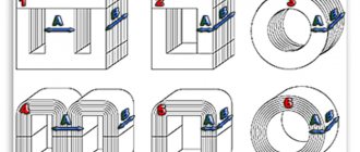
Single drawing mills
Single-pass drawing mills produce thick wire of various profiles and round sections, with a diameter of 25-40 mm, pipes made of ferrous and, to a greater extent, non-ferrous metals. When drawing large-diameter pipes, drums of also large diameter are used. The larger the diameter of the pipe, the larger the diameter of the drum chosen.
The workpieces are placed on the drum in only one row, which reduces the mass of the riot. The die moves along the drum, the material is wound without moving the turns along the drum. In this way, the surface and profile of the coils are protected from damage. Rice. 2 shows a mill with a moving die.
Single-shot drawing machines are designed for a force of 0.05-200 kN. This is determined by the characteristics of the material being drawn: cross-section, profile, quality. The drawing speed reaches 5 m/sec.
In single-shot mills, productivity increases due to an increase in the mass of revolts. This occurs both on the unwinding side of the source material and on the winding side of the finished wire. The larger the diameter of the wire being drawn, the greater the weight of the coils, which can be increased by welding.
A single drawing machine with all auxiliary components is shown in Fig. 3.
Gearbox 1, gearbox 2, electric motor 3, unwinding figure 4, sharpening device 5, lift 6 and rack 7.
Receiving devices are used to transfer the wire to subsequent operations. The mill stops only when the receiving devices are changed, which occurs at the moment it is filled. This is a fairly quick procedure. For coils with a large mass of up to 3 tons, special receiving devices are used. The sequentially fed coils are transferred to drawing without stopping the mill, without reducing its speed.
Motors on single-shot drawing mills can be of both direct and alternating current. They must ensure the operation of the mill at creeping speed, smooth start-up of the unit, jog operation, speed control during drawing, and the possibility of emergency stop.
Double drawing mills
Double drawing machines perform the drawing process in two passes, in other words, when two broaches are enough. This is necessary to ensure a given wire size or when production volumes are small. With two broaches, the material is subjected to fourfold compression.
The simplest version of such a mill is to use a two-stage drum. At the first stage, the drum has a smaller diameter, which ensures the sliding of the wire. Different wear of the rolls makes it possible to install the hood 1-2% higher than the hood due to the difference in the diameters of the steps.
Sliding occurs at the bottom step, otherwise the wire may break. There is no possibility to give high compressions here.
Differential double drawing machines operate on both stages without slipping, but allow high as well as low reductions. We see a differential mill operating on the principle of double drawing in Fig. 4. It has two drawing drums located on the same axis.
Multiple stuns
Multiple drawing mills are equipment in which the workpiece is drawn through several dies simultaneously. This is done in order to increase the extraction of the processed material. The dies are located one after another in series.
To determine the drawing ratio, the dimensions of the material being processed, its cross-section, the specified size of the final product and its mechanical properties are essential. Usually the multiplicity is set in the range of 2 - 25, but more can be set.
The stronger the material, the more difficult it is to stretch. There is not enough tension behind the last die to simultaneously pull the material through all the dies of the multiple line. For this purpose, a separate pulling drum is used after each drawing. The pulling drum rotates, the drawn material, leaving the die, is wound onto the drum, at the same time unwinding, and moves on to the next die.
Multiple mills with sliding function
There is a proportion or ratio for all dies of the multiple drawing mill.
This condition is the key to the successful operation of the unit:
F1v1 = F2v2 = … = Fnvn,
in this case F1, F2, ..., Fn is the cross-sectional area of the wire when it leaves the die; v1, v2, ..., vn - speed when winding the wire onto the drum, when the wire comes out of the die.
The volume of material that is pulled through one die in a certain time must be the same for all dies of the mill, otherwise the wire will tear, throw off loops, and then get tangled.
The multiple drawing line shown in Fig. 5a, consists of 7 dies (item 1), sequentially located one after another, and 7 drums (item 2 and 3). The wire for drawing is put on the figure (item 4) (not driven). All seven reels are pulling. Drive pos. 5 and gearbox pos. 6 drive each drum installed for each die for drawing wire.
Several turns of wire are wound onto each drum, position 2. In operating mode, each revolution of the drum corresponds to winding one turn. In this case, one turn is wound from above. This is how a constant number of turns on the drum is ensured. The drawn wire as a finished product is wound onto a drum pos. 3.
During the operation of the mill, its dies naturally wear out. There may be inaccuracies in the manufacture of dies. Both aspects can cause a discrepancy between the peripheral speed of the drums and the speed of movement when pulling the wire between the dies.
It may turn out that the pulling speed will be some value greater than the peripheral speed of the intermediate drum. The drum will not be able to produce pulling force. In this regard, on mills of this type, with a sliding function, the peripheral speed of the internal drums is chosen to be 2-4% higher than the speed of the wire when it leaves the die. Due to this difference in the relative speeds of the drums, except for the last drum, the wire slips. This determines the name of the drawing mill “sliding mill”.
Repeated drawing machines with sliding function are suitable for wire drawing production of soft materials such as copper, aluminum and mild steel. Made from durable steel, the wire slips only slightly. Otherwise, if there is strong sliding, the wire will become very hot, and significant wear on the surface of the drum will occur. And the surface of the wire itself will become rough.
When producing thin wire (less than 0.5-0.1 mm in diameter), step mills are used. For an example of such a mill, see Fig. 6. The designs of such mills include max. four drawing spindles and a maximum of 25 dies. In this case, it is necessary to select the dimensions of the dies and the diameters of the drums in stages. We see the wire drawing speeds on today's multiple mills in the following table:
| Wire | Copper | Steel |
| Thick and medium | 5-18 | 2,5-10 |
| Thin and finest | 30-80 | 5-25 |
| The thinnest | 20-40 | — |
Multiple mills without sliding function.
This type of mill resembles multiple drawing mills with a sliding function. On a mill without a sliding function, dies and pulling drums are also located in series. But there is a cumulative function here, i.e. the ability to collect wire between two dies located one behind the other. There is no need to adjust the speed of the drums and the speed of pulling the wire after the drawing. The loop accumulates, as in the accumulator of a wire rolling mill.
There are various types and designs for multiple drawing mills with different drawing ratios without a sliding function.
Figure 6 shows a mill with 4-fold drawing. Under item 1 there are 4 drums located alternately one after another. Pos. 2 displays dies with holders (6 dies). When unwinding, the wire goes to the roller (pos. 5) of the driving ring (pos. 3). The roller (pos. 5) and the wiring device (pos. 4) guide the wire into the die (pos. 2).
Each drum, except the drum for finished wire, is equipped with driving rings and wiring devices. Drive rings have a braking effect, preventing the wire from unexpected unwinding, which can occur under the influence of centrifugal forces.
With this design, the unwinding of the wire from the drum occurs regardless of its winding. In this case, several turns of wire may accumulate on the drums, but the speed when unwinding the wire will not depend on the speed that occurs when winding the wire.
The unwinding speed is adjusted according to the speed of threading the wire into the next die. Mills of this type can be equipped with both a group drive and an individual one (Fig. 7). Individual, that is, each drum will be equipped with a separate drive. When using individual drives, more stringent requirements are imposed on them. They extend in relation to a soft start, thereby avoiding wire breakage.
Below are figs. 6 and fig. 7, which shows multiple drawing mills with individual and group drives.
Twin Drum Mills
In multiple drawing mills, where wire accumulates and can begin to curl, new ideas have been developed and applied. These developments are aimed at a method for winding wire onto drums and transporting it to the next die.
Shown in Fig. 8 mill represents a structure made of blocks. The number of blocks is equal to the drawing ratio. This type of design differs from the designs of conventional mills in that the spindle is equipped with two drums. The drums are installed one above the other. The drum at the bottom is fixed to the spindle with a key. The upper drum rotates freely thanks to the rolling bearings on which it is mounted on the spindle.
The wire is guided by a roller from bottom to top. It is wound onto the drums in opposite directions. See Figure 9. The wire, accumulating on both drums, upper and lower, goes down the rollers (2 guide rollers) to the drag of the next block. The process is repeated in the same way as in the 1st block.
The ends mounted on the drums fix the maximum and minimum wire reserves on the drums. When the maximum supply is reached, the end is triggered and stops the drum. As soon as the wire supply is again minimal, the other end gives a signal to start the drum.
If the upper drum is at rest, the guide roller rotates slower than the lower drum (twice). This promotes equal accumulation of wire on both drums with the same diameters.
With a slower winding of wire from the upper drum compared to winding on the lower drum, the accumulation of wire on both drums increases, and the guide roller makes rotation around the spindle axis slower than the difference in speed of the two drums, exactly twice.
If the amount of wire removed from the upper drum is equal to the amount of wire that was formed as a result of winding on the lower drum, then the guide roller does not rotate around the spindle axis. When the amount of wire wound from the upper drum exceeds the amount formed as a result of winding on the lower drum, the wire accumulates more slowly. The roller begins to rotate in relation to the rotation of the lower drum in the opposite direction, and the speed of rotation of the roller is lower than the difference between the rotation speeds of the upper and lower drums (exactly twice).
The drums of these mills are equipped with individual drives. The design of these mills has, along with a number of advantages (the wire does not twist, the finished wire can be removed from the drum and the spools can be replaced without stopping the unit, any drum can be stopped separately, an AC drive can be used) its disadvantages, which consist in numerous bends of the wire. As a result, it is difficult to thread the mill when there is wire with a large cross-section, which is intended for the drawing process.
Mills with a different drum design work on the same principle of operation, when they are placed one inside the other. Mills that have a counter-tension function are considered improved.
Multiple counter-tensioning machines or loop machines.
Counter-tension helps reduce die wear and the wire becomes more uniform in thickness. This makes it possible to perform the drawing process at high speeds.
Counter-tension is created by adjusting the speed of rotation of the drums, thereby preventing the wire from sliding along the drum. Such mills are equipped in the same way as other multiple drawing mills: several drums located one behind the other and dies installed between the drums.
See fig. 10. The designs of the drums on such mills are similar to the designs of the drums of new mills equipped with a sliding function. Motors are frequency controlled. Adjusting the speed of the drums ensures continuous wire drawing without slipping.
The wire goes around the drum, heading towards the tension roller, then goes around the idle roller, which is motionless, moving towards the die. After leaving the die, the wire goes to the next drum, and the process repeats. We see the direction of the wire in Fig. 10. It is indicated by arrows.
1 — finishing drum block; 2 — intermediate drum block; 3 - buffer; 4 - tension roller; 5 — speed controller; 6, 8, 10 — soap dishes; 7 — stepped drum block; 9 — guide roller; 11 — fan; 12, 13 — under-engine plates; 14 — gear coupling; 15 — electrical blocking of the panel; 16 — drawing speed meter: 17 — plate under the blocks; 18 — electric motor; 19 — shield; 20 - oil drain; 21 - foot barrier; 22 - manual barrier
In Fig. 12 shows an intermediate drum.
The drum position 1 is mounted on the spindle position 2. Motor drive using a gear coupling, multi-start worm pos. 4 and the worm wheel pos. 3 sets the drum in motion. A separate block consists of a drum pos. 1, spindle pos. 2, gear housing, represented by the upper pos. 6 and lower pos. 5 parts of it. The number of passes during the drawing process determines the number of blocks subsequently mounted on the frame. Due to the fact that such drawing machines are high-speed, only a few turns are wound on the drums, the drum and wire are heated, and they need to be cooled. Water is supplied to cool the drums. The wire is cooled with air. The dies are mounted in a so-called soap box and cooled with water. The mill structure is shown in Fig. 13.
The emergency switch turns off the unit if the wire gets tangled. Mills equipped with a counter-tension function have a number of advantages:
- when transporting wire between drums, it does not twist;
- counter-tension is created by automatically adjusting the speed of the drums;
- the counter-tension function helps reduce wear on the dies and reduce heating of the wire; this improves the quality of the wire and ensures high-speed drawing;
- there is no need to remove the wire from above, which eliminates injury to operating personnel.
This design of loop drawing mills has a number of disadvantages:
- when producing wire from high-strength steel, it is difficult to feed the mill;
- a large number of rollers (tension rollers, guides) creates additional bends for the wire;
- counter tension is adjustable within a small range;
- the forced use of direct current leads to increased cost and complexity of this design.
These disadvantages are not inherent in straight-through mills with a counter-tension function.
Loopless mills (direct flow)
In Fig. 14 cm another mill design with counter-tension function.
On this unit, only a few turns are wound on the drums (from 6 to 10 wire turns per drum). These turns are quite enough to create the necessary friction force concentrated between the drum and the wire. The strip is pulled through the dies without slipping. The wire is transported without rollers, which prevents the strip from twisting during the transition.
Counter tension on loopless mills is created by electric motors. This allows higher counter-tensions to be applied and adjusted over wider ranges. The fact that these mills do not have so many different rollers makes it easier to thread the mill when drawing thick wire from high-strength materials. Not all types of wire allow large crimps. It is for them that the use of countertension is important and effective. Shaped wire is produced using small crimps. This reduces wear on the dies.
When producing low and high carbon steel wires, the back tension used is max. 10-15% of the total drawing force. In Fig. Figure 14 shows a mill for the production of wire from high-carbon steel grades by drawing. The mill drums are equipped with an individual DC drive. The drums are connected in series.
The torque is adjusted so that its excess determines the amount of counter-tension. The speed is adjusted only on the finished wire drum, the other drums are adjusted automatically based on the rotation speed of the finished wire drum and the reductions used in each die.
When threading the mill, the motor adjustment continues until its torque is sufficient to pull the wire through the die and create tension to turn the drum (back tension). It reduces pressure on the walls, and thereby reduces friction and heating.
With less heat, you can set a high speed during the drawing process. Excessive heating destroys the lubricant and reduces the quality of the wire and its surface. In such units, water is supplied to the drums and dies for cooling purposes, and cooling air is supplied to the wire.
Cooling helps to reduce the heating temperature of the wire and increases its tensile strength.
Mills of this type have the following positive aspects:
- when drawing the wire does not twist,
- provides drawing of wires of various profiles and non-circular cross-sections,
- wide range of counter-tension adjustment,
- there is no difficulty in refueling the mill,
- no rollers - no unnecessary wire bends,
- no speed controller,
- simplified diagram of the unit (mechanical and electrical).
Perhaps, the use of low voltage DC electric motors (less than 110 V) is one of the significant disadvantages of this design of such mills.
Drawing mill developers are currently making efforts to invent straight-through mills with AC drives. In Fig. 16a shows a fairly simple design of this type of mill, consisting of a squirrel-cage electric motor with a magnetic coupling. The coupling is installed between the electric motor and the gearbox.
In Fig. 16b demonstrates the following type of drive, which creates a differential transmission. It is located between the electric motor and the gear train. Setting the speed of the drums directly depends on changing the compression mode. The speed is adjusted automatically.
When changing the compression mode, it is necessary to change the gear ratio on all drums. This is done on all straight-through mills that are equipped with AC drives. And the drives can be both individual and group. Individual - each block has a separate drive, and group - this is when one common drive is installed on all blocks at once.
The rapid change of modes during the operation of such mills is an indicator of its productivity. And the faster the mill operators begin to acquire skills in operating and servicing the unit. By turning the handle of just one switch on a mill equipped with a DC drive, the operator switches all the drums to a different speed. AC drives are more complex for such a simple switching of drawing speeds; here it is associated with switching gears in all gearboxes and in gearboxes, or switching is undertaken in both control units at once.
And most importantly, on AC drives it is difficult to enable soft start or smooth acceleration, which is very important when switching speeds, especially in the direction of increasing it.
This problem can be improved through the use of hydrodynamic couplings, because they help to significantly reduce the dynamic loads on gears when changing modes, when starting or stopping the unit, and also reduce the likelihood of wire breakage due to switching from one operating mode of the mill to another.
Mills with an AC drive cost less in terms of money than mills with a DC drive. But the latter, i.e. DC drives are more convenient to maintain and control. They have a much larger speed control range on all reels, and when changing the compression mode, the speed is adjusted automatically.
Wire drawing production lines
Multiple drawing mills are, as is known, production lines. This means that the process on the line goes on continuously, from the delivery of blanks to the receipt of the finished wire, without stopping the line. Such mills process wire, deforming it as much as possible, stretching it between heat treatments or immediately crimping it to a given size.
Using this technology, it is possible to combine several single drawing mills in one line. By combining units in this way that were previously located in different parts of the workshop, time is saved on the costs of operations and transportation of workpieces.
Production lines are assembled from similar equipment according to power data, otherwise the overall productivity of the newly equipped production line may drop.
Combination of mechanical descaling and drawing operations
Today there are many combined lines known. Just as units for removing scale from products mechanically are combined with pickling lines, today devices for removing scale (mechanically) are combined with drawing mills (single and multiple drawing).
With this combination of two units we have the following positive aspects:
- there is no need to feed wire rod from the warehouse to the pickling line,
- then pickle there, do washing, liming or apply protective coatings,
- subsequently transport the wire rod to the drawing production.
The pickling line, which occupies large areas in the workshops, is difficult to combine with the drawing mill.
However, new mechanical descaling equipment, which is as productive as a modern drawing mill, makes it possible to create a combination of these two units.
Combining these offers the following advantages:
- staff reduction,
- reduction of associated costs,
- mechanical descaling equipment costs significantly less than chemical equipment,
- the descaling unit does not take up as much space in the workshop as a full-fledged pickling line,
- there will be no waste from the pickling unit and the environment will be clean.
Combination of drawing and annealing operations
Combined lines for continuous annealing and drawing processes are becoming more and more famous today and becoming widespread. A similar unit in Fig. 17. These combinations are of greatest value for processing copper wire (0.1-4.0 mm in diameter) in drawing production. The annealing speed varies depending on the thickness of the wire (its diameter). If it has a diameter of 0.15-0.4 mm, then it is annealed at a drawing speed of 22-25 m/sec, wire with a diameter of 0.4 to 1.0 mm is annealed at a maximum speed of 20 m/sec. Large diameter wire (1-4 mm) is annealed slowly (up to 6.5 m/sec.).
In the process of producing aluminum wire, combined technological operations were also developed: a continuous aluminum casting process with continuous rolling and drawing.
With regard to ferrous wires, there is an initial stage of implementation in the area of combining drawing and annealing processes. Work on the implementation of such a unit is being carried out at the Magnitogorsk Metalware Plant.
There are a number of combined lines, which include a number of units, for example, for the processes of drawing, annealing, tinning and applying insulating coating to wire. All these processes are continuous and high-speed, so at the beginning and end of the line there are, respectively, unwinders and coilers, which guarantee continuous supply of workpieces and removal of finished wire without stopping the line.
The advantages of such combined lines:
- great economic effect,
- the need for auxiliary equipment is reduced,
- significant reduction in production space,
- significant reduction in production costs,
- there is no transportation of raw material for transfer from one process department to another.
Multi-thread drawing
We come across the concept of “multi-strand drawing” when drawing particularly thin wires from non-ferrous metals. Multifilament mills operate in continuous production mode; stopping the unit is not required to thread each coil or remove the finished wire. Wire drawing in such installations is combined with the process of annealing and coating the product. In combinations of this kind, the speed of the slower processing takes priority. There are 18-thread drawing machines, where the processing speed is no higher than 5 m/sec. In total, the speed reaches 90 m/sec.
Advantages of low speed on a similar mill:
- maintenance of the mill is simplified,
- the likelihood of wire breaks is reduced,
- stability in obtaining quality enameled wire.
If the operations are not combined, the mills are equipped with systems for two- and ten-thread drawing, here processing occurs at a speed of 10-15 m/sec.
The more threads on the mill, the lower the processing speed, and, accordingly, the lower the productivity. But this is explained by the fact that eliminating the consequences of a wire break on a multi-thread mill is associated with a huge loss of time in comparison with a single-thread mill. To increase productivity on a multi-thread mill, you should carefully prepare the material for the process (drawing), select technological lubricant and cooling means for the wire.
Double drawing equipment
The wire drawing machine can crimp the workpiece twice. This allows you to give the workpiece the required shape and size. Such equipment is used in enterprises with a small volume of metal forming. During such processing, the material is subjected to fourfold compression.
The simple design includes a two-stage drum. At the first stage it has a smaller diameter. The workpiece sliding function is often used here. In this case, the hood should be 1-2% greater than the difference in the diameters of these steps. At the lower stage it is impossible to provide high compression. Therefore, to avoid wire breaks, the sliding function is used here.
Differential double drawing mills are also on sale. They do not involve the use of sliding on both stages. In this case, it is possible to carry out both high and low compressions. Two drawing drums in such a device are located on the same axis.
Repeated drawing
Drawing machines can crimp the workpiece several times. In this case, the material is pulled simultaneously through several dies. This allows you to increase the degree of elongation of the workpiece. The dies are sequentially located on the production line.
During processing, the drawing ratio is determined. This indicator is influenced by the initial size of the workpiece, its type of section and the parameters of the final product. The multiplicity can be set in the range from 2 to 25. There are mills that provide an even greater value for this indicator.
It is especially difficult to pull strong materials. In this case, there may not be enough tension behind the last wire. Therefore, it is problematic to pull the material through all the line dies at the same time. To make such processing possible, a pulling drum is installed after each die. The workpiece is wound onto it, and then proceeds to the next processing stage.
Wire drawing processes
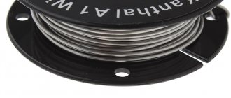
Rough drawing
Rough drawing starts at an input diameter of 8 mm, and with an output wire diameter of 4.5 mm.
up to 1 mm. Rough drawing processes require good lubrication due to the large reduction in cross-sectional diameter and deformation. The high degree of deformation and reduction in cross-section during rough drawing generate a huge amount of heat, which must be removed from the drawing machine, so wet wire drawing is carried out.
The drawing emulsion used should have a large droplet size for a thick layer of lubricant.
Our products for rough copper wire drawing
Multidraw CU ROD is a semi-synthetic oil with a high degree of lubrication, for rough drawing, on single-core and double-core drawing machines with the possibility of applying lubrication by spraying.
The maximum final wire diameter is up to 1 mm. This product is specially designed for rough drawing processes.
The product guarantees high temperature stability, even under high loads and complex thinning, also under peak temperature loads, the product does not demonstrate excellent stability. The concentration of the product when used should be: 10% – 17%.
Product use in factories: Berkenhof (Germany, CuSi3 welding wire), Prysmian Group (Italy, fire-resistant tinned copper wire cable), Geldra Draht GmbH (Germany, bare copper wires)
Medium and fine drawing
Average drawing: From 3.5 mm. up to 1.5 mm. – 0.2 mm.
Water-miscible emulsions are mainly used.
Fine drawing: From 2.6 mm. – 1.6 mm. up to 0.5 mm. – 0.05 mm.
The same coolants are used for drawing copper wire as for medium drawing, up to a diameter of 0.1 mm.
Direct-flow loopless units
Drawing machines of the loopless type involve winding only a few turns of the finished product (6-10 pcs.) onto a drum. This is quite enough to provide the required friction force. In this case, the strip is pulled along the line without slipping. Transportation is carried out without rollers.
Electric motors create counter-tension. The absence of a large number of rollers greatly simplifies the maintenance procedure and filling the mill during drawing of strong, thick workpieces. If the wire cannot be subjected to significant reduction, this type of mill will produce high quality products using counter-tension.
The line's drums are equipped with personal electric drives. They are connected in series. In this case, in the process of adjusting the torque, its excess determines the counter-tension indicator. The speed can only be adjusted on the drum that feeds the finished wire. The remaining elements are configured automatically.
Having examined the features and types of drawing mills, you can understand the principle of their operation, as well as the features of using such equipment in production processes.