The main element of the transformer is the magnetic circuit. This is a system through which the magnetic flux is closed, which serves as the basis for attaching windings and other elements of the device. Plates made of thin electrical steel serve as structural elements for assembling transformers. They are insulated using a heat-resistant coating, which is applied by the manufacturer, or varnish, applied after stamping the plates.
Design and features
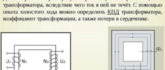
The main design difference between the armored transformer (BT) and other single-phase transformers can be easily seen in Figure 1, b.
Rice. 1 – Schemes of single-phase transformers
Figures 1a and 1c show rod (ST) and toroidal (TT), respectively. The CT design scheme is opposite to the BT scheme in terms of the location of the main elements relative to each other, and in the first it is the other way around - the core is covered by windings. The BT, in comparison with the ST, has fewer outputs for the same number of windings, since the primary winding of the ST must be distributed in two equal parts between the magnetic conductor rods.
In this regard, in certain cases with CT there are difficulties in placing the leads, however, if the core is detachable tape, then the CT will even have an advantage, manifested in the ability to provide a small gap in the core and tighten its two halves.
Characteristic
The mere presence of such parts leads to an increase in weight and volume. The armored design to some extent reduces the dimensions of the BT, while the side yokes serve as protection against mechanical stress for the windings. This is extremely important, given the small dimensions, the absence of a casing and the location together with other equipment on the circuit, and not separately. The TT has the smallest number of elements, which means its dimensions are least susceptible to growth, but at the same time it is also structurally the least technologically advanced.
Technological disadvantages are expressed, firstly, in the need for sequential production of the core and coils (lengthening the production cycle), and secondly, in low productivity during winding of the latter.
In addition to this, the toroidal winding machine is significantly more complex and expensive compared to conventional line winding machines, and cannot be used for winding wire whose diameter exceeds 2 mm. This narrows the scope of CT application at high powers, while at very low powers the core window may not be enough to pass the shuttle. It is especially difficult to wind CTs at a given frequency of 50 Hz, when a lot of turns are needed.
Against the background of the above, another significant advantage of BT appears - it is the most technologically advanced solution in conditions of low power, with stamped cores. Moreover, its superiority in relation to CT is also weighty - only one coil is required, not two. In general, the difference between two coils and one always comes to the fore when small-sized transformers are required.
Varieties
There are many types of CTs, but in the most general form, the choice of current transformers takes into account that products are divided into measuring ones (TTI) and for protection.
Separation factorSpecies
| Purpose |
|
| Design | In windings, the primary is connected in series to the conductor being measured. In toroidal ones, instead of it there is a network line (in the CT hole), and in rod ones, in its role there is a circuit cable, which is equivalent to 1 turn. |
| Installation |
|
| Number of turns |
|
| Insulation |
|
| steps | One or more (cascaded) |
| At what denomination | Up to 1 kV and higher (for example, for current 10 kV) |
The current transformer can be configured to be opened, installed and locked, without shutting down, in online mode.
Protective CTs
Protective transformers are usually of the relay type, “monitoring” that the person carrying out manipulations who enters the electrical network of the power plant does not receive a fatal blow. Inside electrical systems that create, transport, distribute energy, there are dangerous values for correct operation. But any equipment requires inspection, repair, and maintenance, so a safety “window” in the form of TT is left for repair specialists.
Measuring CTs
The task of the measuring current transformer TTI is to convert values, creating the ability to connect a voltmeter, ammeter, or other meter without fear that it will burn out from excessive load. In this case, the most accurate and reliable measurement data is obtained. In other words, the TT isolates the connected device, not only for measurements, but also any other device as needed, from high powers.
Principle of operation
Any single-phase transformer operates on the principle of transmitting from the input (primary winding) to the output (output contacts of the secondary winding) a complete repetition of the input voltage in terms of the ratio of turns in the secondary and primary windings. By applying voltage U1 to the primary and connecting the secondary to the load, we obtain currents I1 and I2 in each, respectively. These currents will generate magnetic fluxes F1 and F2 directed towards each other. The total magnetic flux in the magnetic circuit will decrease, as a result of which the emf E1 and E2 induced by it will decrease.
U1 will remain the same, and a decrease in E1 will cause an increase in I1. With an increase in I1, F1 will increase until the demagnetizing effect of F2 is compensated. Equilibrium is restored when the total flow reaches its previous value.
Main characteristics
The idle mode is used when the secondary circuit of the transformer is open; there is no voltage in it. The current passes through the primary coil, and reactive magnetization occurs. Using idle operation, the efficiency, transformation index and core losses are determined.
Operation under load involves connecting the power source to the primary circuit, where the total operating and no-load current flows. The load is connected to the secondary circuit of the transformer. This mode is common.
The short circuit phase occurs if the resistance of the secondary spiral is the only load. In this mode, the heating losses of the coil in the circuit are determined. Transformer parameters are taken into account in the device replacement system by setting the resistance.
The ratio of consumed and output power determines the efficiency of the transformer.
Types
In operating condition, the transformer core is constantly exposed to an alternating magnetic field, which causes the formation of eddy currents around it. This leads to heating of the magnetic circuit, which means useful energy is wasted. The percentage of losses depends on:
- core material;
- frequency response of magnetization reversal;
- maximum magnetic induction.
The easier it is to magnetize a metal, the easier it is to remagnetize with a mutual reduction in losses. Therefore, the cores are made from steel with pronounced magnetic properties. The phenomenon of eddy currents in monolithic conductors is gaining maximum momentum, since the material is endowed with low resistance. To reduce losses associated with this, this resistance is increased by assembling a magnetic circuit from steel sheets not exceeding 0.5 mm in thickness, with insulation in the form of varnish and scale. The insulating layer does not allow eddy currents to affect the magnetic flux in the core, which has a positive effect on losses. Assembly is carried out using one of two technologies:
- end-to-end - the core itself is assembled, then windings are placed on it, at the final stage everything is fastened together with a yoke (a simpler method, but losses are higher);
- interlacing (lamping) - the plates of each next row overlap the joints of the previous one (greater demand due to lower losses).
The geometry and type of magnetic circuit determine the typical differences between transformers. The type of magnetic circuit can be tape or plate. In turn, its shape gives the name and designation: armored magnetic cores are made W-shaped and are designated by the letter Ш, rod ones are U-shaped and P, ring ones are O-shaped and O, three-phase magnetic cores are made E-shaped, and orthogonal ones are designated three letters OPL. For tape magnetic cores, the letter L is added to the designation, for example, ШЛ, PL, OL, EL.
Thus, the armored transformer can be type Sh or ShL.
Sh
The most common type of BT. The middle rod with the general flow passing through it is closed by two outer rods. The cross-section of the outer rods is equal to half the cross-section of the middle one.
SHL
Tape (twisted) armor magnetic cores ШЛ also have the following subtypes:
- ShLM – with a reduced I1/I ratio;
- SHLO – with an extended window;
- ShLP – with an increased B/l ratio;
Why is this necessary?
The transformer is used to increase or decrease the supplied electricity. Why do you need to convert current? The point is that, according to the Joule-Lenz law, the heat that a conductor releases when an electric current passes through it is released depending on the strength of the current. Moreover, this dependence is quadratic, since the current strength in the formula has a second degree.
In practice, this means that increasing the current by 2 times will lead to an increase in heat generation by 4 times. Everything would be fine, but no one has yet canceled the law of conservation of energy. Heating the conductor consumes electricity, which humanity struggles to obtain. The only way out is to increase the voltage to the maximum.
According to Ohm's law, a certain equality is always maintained: the product of current and resistance is equal to the voltage in the network. Let us assume that the resistance does not change, since it depends on the properties of the conductive material. Then the only way out will be to raise the voltage as much as possible in order to reduce the current in the network.
High-voltage lines were not invented for fun. The only goal of such a complex system with transformers is to reduce losses as much as possible.
Sources
- https://odinelectric.ru/equipment/chto-takoe-transformator
- https://ProFazu.ru/elektrosnabzhenie/elektroset/transformator-toka-printsip-raboty.html
- https://lightika.com/osveshhenie/ustroystvo-i-princip-raboty-transformatora.html
- https://www.kipiavp.ru/pribori/transformator.html
- https://www.techcult.ru/science/5124-princip-dejstviya-transformatora
- https://www.RusElectronic.com/ustrojstvo-transformatora/
- https://principraboty.ru/princip-raboty-silovogo-transformatora/
Purpose and application
Armored transformers are not labor-intensive and cheap to manufacture, and for signal small/medium power (up to 100 W) transformers, the armored type is usually chosen. BT, however, are also the most sensitive to interference, and they also have a large leakage inductance. The ShL and ShLM series are used when the smallest weight, rated power of no more than 100 W and a frequency of 400 Hz (ShL) or 50 Hz (ShLM) are needed. The ShLO series is used in low voltage conditions at frequencies from 1 to 5 kHz and high voltages at frequencies from 50 Hz to 5 kHz.
The Soviet tape small-sized low-power transformer - TPP - is distinguished by low voltages on the secondary windings. TPPs perform well in circuits of household appliances, in radio-electronic and communication devices, and computer systems powered by industrial and special networks with alternating current at voltages of 40, 115, 127 and 220 V and a frequency of 50 or 400 Hz. They are characterized by a wide range of voltages and currents with a power of up to 500 VA.
Self-assembly of TT
Creating a CT with your own hands is a separate topic, since the procedure will require a broad description of calculations with formulas, but in a simplified way the process looks like winding the calculated number of turns of copper wire onto a rod (iron, steel).
The basis is a well-known principle. The currents on the primary and secondary are denoted by the ratio. For example, 100/5: the value on the first is 20 times higher than that on the second, that is, when it has 100 A, then the other will have 5 A. Product 500/5 reduces 500 A to 5 A (on the secondary turns). The indicated values depend on the ratio of the number of turns.
How to calculate
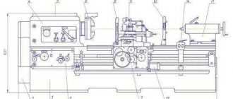
Almost any calculations must begin with core measurements. Figures 2, c and 3 show the quantities that need to be measured at the BT in a schematic and visual display, respectively.
Rice. 2 – Measurement of core dimensions according to the diagram.
Rice. 3 – Measuring the dimensions of the core by appearance.
Secondary power
P2 = 2 * Pgab – P1,
where Pgab is the overall power (W), P1 is the power of the primary winding (W).
Overall power
Pgab = (n * Sc * So * 4.44 * f * B * j * Km * Ks) / ((1 + n) * 100),
where n is the tabulated efficiency of the transformer, Sc is the cross-sectional area of the magnetic core (cm²), So is the cross-sectional area of the window (cm²), f is the frequency (equal to 50 Hz), B is the magnetic induction (T), j is the tabulated current density in coil wires (A/mm2), Km – coefficient of filling of the magnetic circuit window with copper, Kс –…steel.
Actual steel section
Sc = a * b,
where a is the width of the rod, b is the thickness of the magnetic circuit according to Figure 2 or 3.
Actual cross-sectional area of the core window
So = h * c,
where h is the height of the window, c is the width of the window according to Figure 2 or 3.
The value of the rated current of the primary winding
P1 = U1 * I1
where I1 is the current in the primary winding (A).
Rated current in windings
I = Spr * j,
where Spr – wire cross-section (mm²).
Winding wire cross-section
Spr = 3.14 * R²,
where I is the current in the winding (A), R is the radius of the wire (mm).
Diameter of winding wires without insulation
d = 2 * √ (I / (3.14 * j))
Number of turns of each winding
W1 = U1 / u1
W2 = U2 / u2,
where W1 is the number of turns of the primary, W2 - ...secondary, U1 - the value of the input voltage on the primary (V), U2 - the output voltage on the secondary (V), u1 - the value of the voltage on one turn of the primary (V), u2 - ... the secondary (V ).
Number of turns per volt
w1 = W1 / U1
w2 = W2 / U2
For the same wire we have the same values in both windings, that is:
w1=w2
The maximum power that the magnetic circuit can provide
Pmax = Sc²
Installation, connection, dangerous factors
If the insulation of the windings breaks down, the possibility of electric shock arises, but the risk is prevented by grounding the output (indicated on the housing) of the secondary.
The currents at the terminals of the secondary coil I1 and I2 are polar; they must be permanently connected to the load. Energy flowing through the primary circuit with significant potential (S=UI). In the other, a transformation occurs, and when it breaks, the tension drops there. The potential of open ends when energy flows is high, which poses a significant danger.
For the reasons described above, all secondary CT circuits are assembled especially carefully and reliably; shunt short circuits are always installed on them and cores taken out of operation.
How is the TT connected?
There are several schemes for protective products. Let's consider connecting a CT to three-phase voltage.
Full star:
- the most common, protection of single- and multi-phase systems against short circuit;
- three CTs are connected into a star.
If the current is below the settings on relays KA1–KA3, then this is a normal situation, the protection is not activated. The current at K0 is the sum of all 3 phases. As the values in one of them increase, the current in the CT also increases. The relay will operate in case of short circuit and when the load is exceeded.
Partial star:
- protection against phase-to-phase faults to create circuits with a neutral grounded;
- for low power receivers with other protection options.
Delta and star circuit - for differential protection.
A circuit without de-energizing during a ground fault is used, but rarely for the same reason. For protection against short circuits between phases and surges in one of them.
TTIs are connected by simple serial connection of the primary turns of the product.
Installation
Installation of current transformers:
- Inspection of the device, checking the insulation (must be above 1 kOhm per 1 V);
- Switch off the power supply;
- Make sure there is no power, fix the grounding.
- Marking, installation of fasteners. It is prohibited to place the transformer close to the power plant (minimum gap - 10 cm).
- Signs and fences are put up.
- The primary turns are connected in series, but with a load on the secondary ones. If it is not possible to connect the meter, then its contacts are closed so that there is no high power on it, which will damage it.
The CT does not allow idle operation; its mode is close to short circuit: the secondary turns are necessarily closed when the device is connected to the measured current. Otherwise, overheating occurs, damaging the insulation. Before disconnecting the meters, first short-circuit the coils. Some models have terminals and jumpers for this purpose.
Calculation
The current transformer can be calculated using online calculators and selected according to its nominal value (for example, for 10 kV). But these are too simplified tools. Calculus and parameters to choose from is an extremely broad topic, so let's cover the basics.
Accuracy is extremely important, so careful calculations by specialists will be required. You need to know many specific nuances, for example:
- for different connection schemes and types of short circuit, there are different formulas for determining resistance;
- check the primary current for thermal and electrodynamic resistance;
- There are some nuances for CTs, for relay protection and for accounting purposes and measurements.
Rules for choosing a current transformer in general terms:
- the rated operating voltage of the CT must exceed or be compared with the rated power plant (standard values 0.66, 3, 6, 10, 15, 20, 24, 27, 35, 110, 150, 220, 330, 750 kV). If the equipment being serviced has 10 kV, then the product must be designed for this indicator;
- the primary current of the CT is greater than the rated current of the power plant, but taking into account the overload capacity;
- CTs are assessed by the rated power of the secondary load, which must exceed its calculated value. (Snom>=Sload);
- evaluate the dimensions and location for installation, rated loads (there is a table), time to failure, service life, accuracy class.
Check after calculation
Rules:
- After calculation, the CT is checked by loading at max. and min. values of loads flowing through it;
- according to clause 1.5. 17 PUE at max. connected load, the current in the secondary coil is at least 40% of the meter rating, at min. — not less than 5%;
- Max. the load should be from 40%, and min. - from 5%, and in any case it should not exceed 100%, otherwise the transformer will be overloaded;
- if the calculated values of max./min. loads are less than 40% and 5%, respectively, then you need to select a product with a lower rating, and if this cannot be done according to the parameters of max. load, it is necessary to provide for the installation of two meters - for max. and min. loads.
Checking a step-down transformer with a multimeter
Let's say a 4-pin transformer - two wires from the primary winding and two from the secondary. Checking it comes down to identifying damage in the windings. To determine whether there are any, first we’ll switch the multimeter to diode testing mode or move the switch to the resistance scale. Then we check one coil, without paying attention to the polarity of connecting the probes, since in this case it is absolutely not important. We do the same with the second one.
Low ohmmeter readings will indicate the serviceability of the windings; lack of tester response will indicate the opposite.
If the affiliation of a particular contact to any of the windings is not known, then it is established during the testing process - the resistance in the primary of the step-down transformer should be slightly higher.
Classification of installations
The division of equipment into classes depends on various parameters.
It can be carried out by:
- Purpose;
- Installation method;
- Number of steps;
- Type of insulation;
- Rated voltage.
Based on the features of use, devices are:
- Measuring;
- Protective;
- Intermediate.
Moreover, the former are divided into current and voltage transformers.
Let's watch the video, the principle of operation and types of transformers:
As for installation, such equipment can be located not only indoors, but also outdoors. Therefore, based on this parameter, the following types of devices are distinguished:
- External;
- Internal;
- Stationary;
- Portable.
The winding insulation of transformers can be either dry, paper-oil or compound. There are differences in the number of steps. Depending on this parameter, devices are divided into:
- Single stage;
- Cascade.
Another distinguishing feature of different models can be the voltage rating. According to its meaning, transformers are classified into low and high voltage.
In addition, power devices can be connected to single or three-phase electrical networks.
High voltage transformers are most often oil cooled. Devices in this series are characterized by high efficiency and good protection against overheating. They require minimal maintenance during operation.
According to their design, power transformers are divided into having the following types of inputs:
- With main porcelain shell insulation;
- With oil barrier;
- With paper-oil;
- With polymer.
- Condenser feedthroughs;
Characteristics and calculation of the transformer
Typically, the main parameters of the device are indicated in the technical documentation included with it. For transformers these are:
- Power and voltage (nominal);
- Maximum winding current;
- Dimensions;
- Weight.
Let's take a closer look at what they mean. The rated power of the device is calculated and indicated by the manufacturer. It is expressed in kilovolt-amperes.
The rated voltage consists of a primary voltage, for which the corresponding winding is designed, and a secondary voltage, measured at the terminals. The value of this parameter can change up to 5% down or up. It can be determined by performing a simplified calculation of the power transformer.
Watch the video and make the correct calculation:
The rated power and current of the device must comply with existing GOST standards. Today, dry models are produced in which this indicator may have the following meaning:
- 160;
- 250;
- 400;
- 630 kVA.
The power of the device is usually indicated in the device passport, and knowing it, you can calculate the rated current value. The following formula is used for this:
I=S√3U, where the values S and U indicate the rated power and voltage.
Based on which winding the current value is calculated for, the quantities included in the formula will also change. It is better to entrust the calculation of the power transformer power to the load to specialists. This will allow you to avoid unpleasant moments during operation.
In addition, the nominal voltage is considered to be the value of the linear value at no load on both windings. Current values are calculated based on the power of the device. When choosing equipment, you should take into account that the calculation of a power toroidal transformer will differ slightly from that given above. You can find information on this issue on the Internet.
Features of installation and operation
Most models of power equipment have a significant weight. Therefore, they are delivered to the installation site by special transport. Moreover, the equipment is delivered assembled and completely ready to be switched on.
Watch the video, starting and diagnosing the equipment:
The device is installed on a pre-prepared foundation or in a special room. To prevent air pockets from forming under the tank cover when installing the device, steel plates are placed under the rollers. Their thickness should be such that a rise of 1% is obtained on the narrow and 1.5% on the wide side of the transformer. The length of the gaskets starts from 150 mm. If the weight of the device does not exceed 2 tons, then it is installed directly on the foundation. Its body must be connected to the grounding network.
However, it should be remembered that before installation the device is tested in laboratory conditions. In the process of carrying out this work, the transformation ratio is measured and the quality of connections is checked. They also test the device with increased insulation voltage and check the conformity of the transformer oil.
After delivery to the site, the device undergoes an external inspection. At the same time, pay attention to the absence of oil leaks and extraneous noise during operation. The condition of the bushings and contact connections is checked for heat damage.
After starting the transformer, it is necessary to periodically monitor the temperature. Measurements are performed using glass thermometers. They are immersed in a special sleeve located on the lid of the device. The temperature here should not exceed 95°C.
To avoid emergency situations in the operation of the transformer, it is necessary to regularly measure the loads. This will allow you to determine phase imbalances leading to voltage distortion. Inspection of equipment without shutting it down should be performed every six months. But depending on the condition of the device, the timing may vary.
Ferrite grades
Ferrites according to their composition are divided into two groups: manganese-zinc and nickel-zinc. Manganese-zinc ferrites are designated by the letters NM, respectively, nickel-zinc substances are marked by the letters - NN. The number before the letter designation of ferrite means the value of the initial magnetic permeability in units of µinit. This indicator is given with an adjustment to the nominal value. For example, ferrite grade 4000NM has a magnetic permeability with a deviation ranging from – 800 to + 500 µinit.
Magnetic cores are of exceptional importance in the formation of devices such as transformers and other electrical devices. The initial technical characteristics of the devices largely depend on their qualitative composition.
A little history
Thanks to the English physicist Michael Faraday, in 1831, humanity became acquainted with electromagnetic induction. The great scientist was not destined to become the inventor of the transformer, since his experiments involved direct current. The prototype of the device can be considered the unusual induction coil of the Frenchman G. Ruhmkorff, which was presented to the scientific world in 1848.
In 1876, Russian electrical engineer P. N. Yablochkov patented an alternating current transformer with an open core. The device owes its modern appearance to the English brothers Hopkinson, as well as the Romanians K. Tsiperanovsky and O. Blati. With their help, the design acquired a closed magnetic circuit and has preserved the circuit to this day.
Types of magnetic cores
Hysteresis loop
Hysteresis in Greek means delay. The graphical representation of the hysteresis loop reflects the degree of magnetization of a body located in an external magnetic field. Hysteresis is the dependence of magnetization vectors and magnetic field strength in any medium on the applied external MF. The state of the body at a given time is compared with its previous state. In this case, there is a lag in the body’s reaction to the influence of external MF. The physical effect is clearly manifested in ferromagnets: iron, cobalt, nickel and their alloys. The hysteresis loop provides an explanation for the existence of permanent magnets.
Hysteresis loop
Note! Magnetic hysteresis of a ferromagnet is the lag between changes in the degree of magnetization of a body and changes in the external magnetic field. That is, the loop shows the dependence of the degree of magnetization on the sample’s history
The magnetic permeability of a ferromagnet is a variable value; it is closely related to the induction of an external field. The magnetization curve of the core is a curved loop, at a certain degree of saturation of the ferromagnetic field. In the future, this value does not increase. If the external induction is reduced to zero, the ferromagnet will retain residual magnetization. When the direction of the external field changes, the ferromagnet is remagnetized in the opposite direction.
Superconducting electromagnet
Superconductivity is considered the property of materials with resistance close to zero. Electromagnets with practically zero resistance have a super-powerful magnetic field. The force of magnetic influence can cause diamagnetic materials such as pieces of lead and organic objects to float in space.
As physicists have noticed, metals acquire the property of superconductivity at ultra-low temperatures. To obtain the superconductivity effect, the EM windings are placed in a Dewar flask with liquid helium, which is equipped with a valve to release the vapor of the substance. Superconducting magnets are used in medical equipment - MRI (magnetic resonance tomography) machines. Experimental hovercraft trains use superconducting magnets.
Superconducting magnet
Types of magnetic cores
Magnetic cores are made of rod, armor and ring structures.
Rod type
Vertical cores of stepped cross-section form a circle with horizontal yokes. The windings are located only on the vertical elements. The entire magnetic circuit system is arranged in the form of a closed circuit.
Lamellar magnetic cores
Armor type
The cores have a rectangular cross-section. They occupy a horizontal position. The windings are also made in a rectangular shape. In order to implement such an equipment configuration, a rather complex production technology is required. Therefore, this type of MP is used only in special types of transformers.
Ring – toroidal type
Ring tape magnetic cores are used in the assembly of single-phase power transformers. MPs are made from cold-rolled electrical steel with a thickness of 0.08, 0.3 and 0.35 mm. Toroidal cores are made of ferrite or carbonyl iron. They are widely used in radio electronics.
Ring toroidal MPs
Converter power calculation
Each transformer has technical characteristics specified in the passport. It may be necessary to carry out independent winding and power calculations if the data is lost. The power value is important to determine whether a particular inverter can be used.
Before determining the power of the transformer based on the cross-section of the core, the type of magnetic circuit is studied. If the core has a W shape, perform the following calculations:
- measure the thickness of the set of plates;
- measure the central part;
- the results obtained are multiplied.