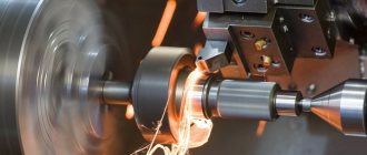
People have long realized the possibility of obtaining smooth and even and even standard surfaces by turning the workpiece while rotating it. The appearance of the first lathe dates back to 650 BC.
Its design was ridiculously simple: 2 coaxial centers, between which the workpiece was inserted. One person rotated this workpiece, and another, using a cutter made of a harder material, turned it.
The parts were mainly made of bone or wood, since there was neither sufficient power for processing metal nor materials of sufficient hardness (so that a chisel could be made). Time passed, technology developed, and so gradually, the machines reached their modern appearance and capabilities.
Classification, types
At the present stage, there are several types of lathes, or rather 9 groups of lathe equipment according to various parameters. It seems interesting to consider them in more detail:
Automatic and semi-automatic
Semi-automatic is a type of equipment in which some processes are not automated. For lathes, these are, as a rule, manipulations associated with loading and removing workpieces.
Semi-automatic machines are very common due to their simpler design, as well as low cost. And at enterprises, semi-automatic machines are used to process non-standard, large-sized workpieces, which does not allow the process to be fully automated.
Semi-automatic machines are divided into:
- by purpose - specialized and universal;
- according to the type of workpiece being processed - for cartridge-type machines and for bar-type machines;
- by the number of spindles - single- and multi-spindle;
- by spindle positioning - vertical and horizontal.
Automatic lathes are those in which all main and auxiliary actions are fully automated (including feeding and removing workpieces, as well as changing the processing tool). Automatic lathes are conventionally divided into 3 groups:
Automatic machines with one camshaft, which rotates at one frequency specified for a given mode of processing the part.
- Automatic machines whose camshaft has at least 2 rotation speeds.
- In machines of this type, in addition to the main shaft, there is also an auxiliary shaft, rotating at a significantly higher frequency.
Multi-spindle
Multi-spindle lathes are those with several spindles for fastening both the workpiece and the processing tool. Processing of a part on such a machine can occur both simultaneously (that is, with the participation of all spindles) and sequentially (that is, at the same time with the use of only one spindle).
As a rule, automatic lathes are multi-spindle. Modern turning “multi-machining” centers provide not only spindles with different rotation speeds, but also those adapted for the use of various types of equipment (drills, cutters, cutters). That is, each spindle has its own force threshold.
Revolving
These are universal machines in the modern sense of the word. Various tools are clamped in the tool holders of the turret-shaped head of the machine. These can be cutters, drills or cutters.
The workpiece is clamped in the chuck and processed with one tool for each pass. After each pass, the head rotates (like the drum of a revolver - hence the name) and the workpiece is processed with the next tool.
As you can understand, such machines provide a great advantage, expressed in saving time when changing tools and workpieces. However, the use of such equipment is economically justified only if it is necessary to process various parts on-line.
Cutting group machines
The functionality of the machines becomes clear from the name. These are highly specialized machines that are produced semi-automatically.
The main task of this equipment is to reduce the diameter of the workpiece to the minimum possible, so that in the future it can be cut on another type of equipment (say, on a milling machine). Or, if the format for fastening the workpiece allows, complete its trimming with processing of the end surface.
Carousel models
Rotary-type lathes are designed for processing cylindrical workpieces whose diameter significantly exceeds their height. Rotary machines have the following characteristic features:
- This equipment is designed to work with large parts. Such machines come in single- or double-column types. In the first case, the diameter of the faceplate does not exceed 1600 mm, and in the second – 25000 mm!
- The machine itself (usually semi-automatic) is of a vertical type and has compact dimensions.
- Taking into account the vertical position of the spindle, the load on the shaft is more uniform than in the case of its horizontal positioning, therefore, rotary machines have a significantly longer technical life.
- Modern rotary machines are easy to use. They are often made in a revolving design.
Frontal and screw-cutting equipment
Frontal lathes are not widely used at present. They are mainly found in shipbuilding enterprises, as well as in repair shops. This is a highly specialized type of equipment (intended for processing short workpieces) whose diameter exceeds the length, however, not so much that there is a need to use a carousel type of equipment.
In addition, on frontal lathes there is no tailstock and mainly the end surface of the workpiece is processed (that is, the work is carried out “head-on” - hence the name).
A screw-cutting lathe is equipped with a lead screw, as well as a lead roller, and is designed for cutting threads on a workpiece while the slide moves along the axis of the machine. However, this machine specialization does not impose restrictions on any other types of turning work. However, such machines are used mainly in small-scale production.
Multi-cutting and polishing
A characteristic feature of multi-cutting machines is their high productivity. Several supports are attached to the frame at once, where the cutters are secured (no other tool can be secured here).
The feed mechanisms on each support, which, as a rule, are also equipped with variators for the speed of their movement, ensure processing of a rotating part clamped in the chuck at each (“critical”) section of its length.
As a result, such machines:
- horizontal type;
- designed for processing long workpieces;
- economically feasible for continuous processing of standard parts.
The main characteristic feature of turning and polishing machines is the high rotation speed of the chuck with the workpiece clamped in it. In addition, the transverse stroke of the caliper has a very small thread pitch (to deepen it even by a millimeter, you will need to turn the handle several dozen times).
Such equipment is needed to raise the class of surface finish, and this requires:
- the maximum possible rotation speed of the workpiece being processed;
- minimal braking effect, for which the chips are removed to a minimum thickness.
Modern models of polishing machines use the vibration effect of the cutter.
Specialized
This type of turning equipment is used to produce similar parts. For example: couplings, pipes; This type includes gear-cutting and turning-backing machines. They are most effective in the operation being performed, but, as a rule, only in one of its varieties.
A feature of specialized machines is the emphasis on quick changes of cutting tools and accessories. Such machines are used in large-scale production
Special purpose
Such lathes are designed for the production of parts in non-serial (that is, small) quantities. These machines are characterized by:
- large amplitude of lateral movement of the caliper;
- extended bed (with a horizontal workpiece);
- lower speed, but greater accuracy and purity of processing.
Special purpose machines include:
- screw-cutting lathes (not to be confused with screw-cutting lathes);
- multi-cutting semi-automatic lathes;
- semi-automatic hydrocopiers.
Grinding machines
- 3A10P
cylindrical grinder Ø 15, St. Petersburg, SPZPS - 3A110
cylindrical grinder Ø 140, Tbilisi - 3A130
cylindrical grinder Ø 280, Lubny - 3A151
cylindrical grinder Ø 200 Kharkov - 3A161
cylindrical grinder Ø 280 Kharkov - 3A164
cylindrical grinder Ø 400, Kharkov - 3A184
centerless cylindrical grinder Ø 80, Vitebsk - 3B12
cylindrical grinding machine Ø 200, Vilnius, Leninokan (Gyumri) - 3B151
cylindrical grinder Ø 200, Kharkov - 3B153
cylindrical grinder Ø 140, Vilnius - 3B161
cylindrical grinder Ø 280, Kharkov - 3B10
cylindrical grinder Ø 100, Vilnius - 3E12
cylindrical grinder Ø 200, Vilnius - 3D180
centerless cylindrical grinder Ø 1..12, Vitebsk - 3E180V
centerless cylindrical grinder Ø 1..10, Vitebsk - 3E183
centerless cylindrical grinder Ø 40, Vitebsk - 3E184
centerless cylindrical grinder Ø 80, Vitebsk - 3K12
cylindrical grinder Ø 200, Leninokan (Gyumri) - 3M131
cylindrical grinder Ø 280, Lubny - 3M132v
cylindrical grinder Ø 280, Kharkov - 3M151
cylindrical grinder Ø 200, Kharkov - 3M152
cylindrical grinder Ø 200, Kharkov - 3M162
cylindrical grinder Ø 280, Kharkov - 3M151F2
CNC cylindrical grinder Ø 200, Kharkov - 3M153
cylindrical grinder Ø 140, Vilnius - 3M174
cylindrical grinder Ø 400, Lubny - 3M175
cylindrical grinder Ø 400, Lubny - 3M182
centerless cylindrical grinder Ø 25, Vitebsk - 3M184
centerless cylindrical grinder Ø 80, Vitebsk - 3M193
cylindrical grinder Ø 560, Kharkov - 3M194
cylindrical grinder Ø 560, Kharkov - 3M196
cylindrical grinder Ø 800, Kharkov - 3M197
cylindrical grinder Ø 800, Kharkov - 3U10A
cylindrical grinder Ø 100, Vilnius - 3U12af11
cylindrical grinder Ø 200, Vilnius - 3U12vf11
cylindrical grinder Ø 200, Leninakan - 3U131
cylindrical grinder Ø 280, Lubny - 3U132
cylindrical grinder Ø 280, Lubny - 3U133
cylindrical grinder Ø 280, Lubny - 3U142
cylindrical grinder Ø 400, Lubny - 3U143
cylindrical grinder Ø 400, Lubny - 3U144
cylindrical grinder Ø 400, Lubny - 312M
cylindrical grinder Ø 200, St. Petersburg, SPZPS - 3130
cylindrical grinder Ø 280, Kharkov - 3131
cylindrical grinder Ø 280, Lubny - 3132
cylindrical grinder Ø 280, Kharkov - 3151
cylindrical grinder Ø 150, Kharkov - 3180
centerless cylindrical grinder Ø 75, Moscow - 3184
centerless cylindrical grinder Ø 75, Vitebsk - B-88
cylindrical grinder Ø 140, Leningrad - KSh-400
ultra-high precision cylindrical grinder Ø 200 × 400 - 3A227, 3A227P
internal grinding Ø 400, Saratov - 3A228
internal grinding Ø 200, Voronezh - 3K227A
internal grinding Ø 400, Saratov - 3K227V
internal grinding Ø 400, Saratov - 3K228A
internal grinding Ø 400, Voronezh, Saratov - 3K228V
internal grinding Ø 400, Voronezh, Saratov - 3K229A
internal grinding Ø 800, Voronezh, Saratov - 3M227VF2
internal grinding machine with CNCØ 400, Saratov - 32K84SF4
coordinate grinding machine with CNC - 3A423
cylindrical grinder for regrinding crankshaft journals Ø 580, Lubny - 3B423
cylindrical grinder for regrinding crankshaft journals Ø 580, Lubny - 3D4230
cylindrical grinder for regrinding crankshaft journals Ø 580, Lubny - 3451
grinding machine Moscow, MSZ - 3A64
sharpening Ø 250 x 650, Vitebsk - 3А64М
sharpening Ø 250 x 650, Vitebsk - 3A64D
sharpening Ø 250 x 600, Vitebsk - 3A662
sharpening machine for hob cutters Ø 200 x 630, Vitebsk - 3B632
sharpening and grinding machine for sharpening cutters Mukachevo - 3B633
sharpening and grinding machine Ø 300, Tiraspol - 3B634
sharpening and grinding machine Ø 400, Mukachevo - 3B662VF2
sharpening machine for CNC hob cutters, Ø 200 x 630, Vitebsk - 3B641
sharpening Chita - 3B642
sharpening Vitebsk - 3B642
sharpening Vitebsk - 3D641E
grinding machine Ø 200 x 400, Vitebsk, Mukachevo - 3D642E
sharpening Vitebsk - 3D692
sharpening Vitebsk - 3E692
sharpening Vitebsk - 3E642
sharpening Vitebsk - 3E642E
sharpening Vitebsk - 3K631
sharpening and grinding machine Ø 150, Mukachevo - 3K634
sharpening and grinding machine Ø 400, Mukachevo - 3L631
sharpening and grinding machine Ø 200, Mukachevo - 3M634
roughing and grinding Saraktash - 3M636
roughing and grinding machine Armavir - 3M642
sharpening Vitebsk - 3622D
diamond sharpening machine for cutters Mukachevo - 3662
sharpening machine for hob cutters Ø 200 x 280, Vitebsk - VZ-318
sharpening Vitebsk - VZ-319
table sharpening Vitebsk - VZ-818
sharpening Vitebsk - TSH-1
tabletop sharpening and grinding machine Ø 250, Orsha - TSh-2
sharpening and grinding machine Ø 300, Orsha - TSh-3
sharpening and grinding machine Ø 400, Orsha - TSh-4
sharpening and grinding machine Ø 400, Orsha - TSh-3.20
sharpening and grinding machine Ø 400, Chelyabinsk - TS-6010S
sharpening and grinding machine Ø 49 Energomash, Sturm - TCPA-7
sharpening machine for circular, frame and band saws Kirov - ET-62
benchtop sharpening and grinding machine Ø 150, Kasimov - 3B70V
surface grinder 160 x 400, Orsha - 3B722
surface grinder 320 x 1000, Lipetsk - 3B724
surface grinder 400 x 2000, Voronezh - 3G71
surface grinder 200 x 630, Orsha - 3G71M
surface grinder 200 x 630, Orsha - 3D722
surface grinder 320 x 1000, Lipetsk - 3D725
surface grinder 630 x 2000, Voronezh - 3D711AF10-1
surface grinder 200 x 450, Orsha - 3D711VF11
surface grinder 200 x 630, Orsha - 3D756
surface grinder with vertical spindle Ø 800, Voronezh - 3E710V
surface grinder 250 x 125, Orsha - 3E711AF1
surface grinder 200 x 450, Orsha - 3E711B
surface grinder 200 x 630, Orsha - 3E711VF1
surface grinder 200 x 630, Orsha - 3E711VF2
surface grinder 200 x 630, Orsha - 3E756, 3E756L
surface grinder Ø 800, Ø 1000, Voronezh - 3L722V, 3L722A
surface grinder 320 x 1000, Lipetsk - 3L741VF10
surface grinder Ø 630, Lipetsk - 3P722V
surface grinder 320 x 1000, Lipetsk - 371
surface grinder 200 x 600, Vitebsk - 372B
surface grinder 300 x 1000, Moscow - 3711
surface grinder 200 x 630, Orsha - PSh-30540M
surface grinder 156 x 400, Tula - 3G833
honing Maikop, Krasnorechensk - 3K833
honing Maikop, Krasnorechensk - SIP-800
machine for testing abrasive wheels Derbent - 395M
profile grinding 20 x 20, Leningrad, SPZPS - 395МФ10
profile grinding with UTsI20 x 20, Leningrad, SPZPS - 3951VF1
profile grinding with digital indicator 50 x 50, Leningrad, SPZPS
3.1. Cylindrical grinding machines
3.2. Internal grinding machines
3.4. Specialized cylindrical grinding machines
3.6. Sharpening and grinding machines
3.7. Surface grinding machines
3.8. Honing machines. Special machines
What accuracy classes exist and how do they differ?
The accuracy class is a generalized characteristic of measuring instruments, which is determined by the limit of errors (main and additional), as well as a number of properties that influence the accuracy of measurements made with their help.
The error limit is the greatest error of the measuring device at which it is suitable for measurement. The limit of permissible basic error is expressed in the form:
- absolute;
- relative;
- given
Errors. The class characterizes the property of accuracy of measurements using this device. And the accuracy of measuring instruments is the quality of a measuring device, which indicates that the error of the measurements is close to zero.
If we are talking about the class of accuracy that is provided, for example, by a lathe, then here we mean the class of surface finish of the part that this equipment is capable of providing during the processing of the workpiece.
Measuring instruments, as well as processing equipment, have the following accuracy classes: 0.01; 0.015; 0.02; 0.025; 0.04; 0.05; 0.1; 0.15; 0.2; 0.25; 0.4; 0.5; 0.6; 1.0; 1.5; 2.0; 2.5; 4.0; 5.0; 6.0. In addition, there are several categories of accuracy classes:
Special
This “Class C” is the highest class of equipment accuracy (both measuring and processing). This class includes machines (in our case, lathes) that must process workpieces to obtain the highest class of surface finish (0.01-0.015).
High
For example, jewelry, medical and laboratory scales have a high level of accuracy. Another name for such equipment is precision. It is marked “class B”. If we are talking about turning equipment, then a high class of cleanliness (0.02-0.025) is provided by polishing lathes.
Normal
The normal accuracy class (the marking is “class H”, but as a rule it is not placed) means such a characteristic of equipment or a part that ensures identical results in no less than 98% of obviously identical objects. The absolute indicator of the normal cleanliness class is in the range (2.0-0.6).
Particularly high
Equipment of a particularly high accuracy class is marked “Class A” for this indicator. When designing high-precision equipment, increased attention is paid to the quality of spindle bearings.
Here, rolling bearings are mainly used, also of high accuracy classes, and sliding bearings are made in the form of adjustable tapered bushings. (All standards here are established by GOST 1969-43).
Increased
This accuracy class is marked “class P”. The use of elements of a higher accuracy class (primarily bearings) increases the cost of the finished product processed on such turning equipment.
However, if it is necessary to obtain a higher class of workpiece processing, then elements of a higher accuracy class are used for positioning machine shafts, where higher accuracy and rotation speed are required.
Drilling machines. Boring machines
- 2A106P
drilling table Ø 6, Molodechno - 2A112
table drill Ø 12 - 2A125
vertical drilling Ø 25, Sterlitamak - 2A135
vertical drilling Ø 35, Sterlitamak - 2A150
vertical drilling Ø 50, Sterlitamak - 2B118
vertical drilling Ø 18, Vitebsk - 2B125
vertical drilling Ø 25, Krasnorechensk - 2G103P
table drill Ø 3, Kalyazin - 2G106P
table drill Ø 6, Yerevan - 2G125
vertical drilling Ø 25, Krasnorechensk - 2G175
vertical drilling Ø 75, Sterlitamak - 2L125
vertical drilling Ø 32, Lipetsk - 2M103P
drilling table Ø 3, Kirovakan - 2M112
drilling table Ø 12, Kirov, (Selmash) - 2M118
drilling table Ø 18, Orenburg - 2N106P
drilling table Ø 6, Molodechno - 2N112
drilling table Ø 12, Perm - 2N115pm
drilling table Ø 15, Perm - 2N118
vertical drilling Ø 18, Molodechno - 2N118-1
vertical drilling Ø 18, Molodechno - 2N125
vertical drilling Ø 25, Sterlitamak - 2N125L
vertical drilling Ø 25, Molodechno - 2N135
vertical drilling Ø 35, Sterlitamak - 2N150
vertical drilling Ø 50, Sterlitamak - 2Р135Ф2
vertical drilling machine with CNC Ø 35, Sterlitamak - 2С50
vertical drilling Ø 50, Sterlitamak - 2S108P
drilling table Ø 8, Molodechno - 2С118
drilling table Ø 18, Chelyabinsk - 2S125MP
vertical drilling Ø 25, Orenburg - 2S125, 2S125-1 (2S125-01), 2S125-04
vertical drilling Ø 25, Sterlitamak - 2С132, 2С132К
vertical drilling Ø 32, Sterlitamak - 2СС1м (2СС1)
drilling table Ø 6, Saratov - 2T118
vertical drilling Ø 18, Gomel, GSZU - 2T125
vertical drilling Ø 25, Gomel, GSZU - 2T140
vertical drilling Ø 40, Gomel, GSZU - 2T150
vertical drilling Ø 50, Gomel, GSZU - 2118
vertical drilling Ø 18, Novocherkassk - 2135
vertical drill Ø 35, Sterlitamak - AS2116m
drilling table Ø 16, Astrakhar - VSN
drilling table Ø 16, Kasimov - VSN-12
desktop thread-cutting machine M3..M8, Vitebsk - GS-520
drilling table Ø 16, Gomel, (GZSU) - GS2112
drilling table Ø 12, Gomel, (GZSU) - GS2116k
drilling table Ø 18, Gomel, (GZSU) - EM-102
drilling table Ø 12, Saratov - ZIM-426
drilling table Ø 6, Novosibirsk - ZIM-427
drilling table Ø 6, Novosibirsk - Corvette-42
drilling table Ø 16, Voronezh - Corvette-44
drilling table Ø 16, Voronezh - Corvette-45
drilling table Ø 13, Voronezh - Corvette-46
drilling table Ø 16, Voronezh - Corvette-47
drilling table Ø 16, Voronezh - Corvette-48
drilling table Ø 16, Voronezh - KS-02
drilling coordinate Ø 12, Kaunas - MS-36
drilling magneticØ 40, Grodno - MS-51
drilling magneticØ 51, Grodno - NS-12
drilling table Ø 12 - NS-12A
drilling table Ø 12, Vilnius - NS-12B
drilling table Ø 12 - NS-16
drilling table Ø 16, Rostov-on-Don - NS-23
drilling table Ø 23, Chelyabinsk - NS-Sh
drilling table Ø 12, Novocherkassk - NSP-2
drilling table Ø 6, Riga - NSF-1
desktop drilling and milling Ø 12, Chelyabinsk - NSF-23
desktop drilling and milling Ø 23, Chelyabinsk - R-175, R-175m
drilling table Ø 16, Chistopol - S-25
table drill Ø 5, Kalyazin - S-106
drilling table Ø 3, Kalyazin - S-155
drilling table Ø 3, Kirovakan - SV-20
tabletop drilling five-spindle Ø 14, Yoshkar-Ola - SNVSH
tabletop drilling Ø 16, Rostov-on-Don - SNVSH-2
drilling table Ø 16, Rostov-on-Don - SNS-12
drilling table Ø 12, Alapaevsk - SUS-1
drilling table Ø 12, Vilnius - SF-1
drilling and milling tabletop Ø 23, Orsha - SF-16, SF-16-02, SF-16-05
drilling and milling tabletop Ø 16, Sterlitamak - TMNS-12
drilling table Ø 12, Tchaikovsky - 2A430
jig boring machine 280 x 560, Kaunas - 2A450
coordinate boring machine 630 x 1100, Moscow (MZKRS), Kuibyshev - 2A470
coordinate boring two-column 1400 x 2240, Leningrad, (Sverdlov) - 2B440A
jig boring machine 400 x 800, Kuibyshev, Samara - 2B460
coordinate boring two-column 1000 x 1600, Leningrad, (Sverdlov) - 2D450
coordinate boring machine 630 x 1120, Moscow (MZKRS) - 2E440A
jig boring machine 400 x 710, Kuibyshev, Samara - 2E450
coordinate boring machine 630 x 1120, Moscow (MZKRS) - 2E450AF1
coordinate boring machine 630 x 1120, Moscow (MZKRS) - 2E450AF30
CNC coordinate boring machine 630 x 1120, Moscow (MZKRS) - 2E460
coordinate boring two-column 1000 x 1600, Leningrad, (Sverdlov) - 2E470
coordinate boring two-column 1400 x 2240, Leningrad, (Sverdlov) - 24K40SF4
jig boring machine 400 x 800, Kuibyshev, Samara - 2421
jig boring machine 250 x 450, Kaunas - 2431
coordinate boring 320 x 560, Kaunas - 2431sf10
jig boring machine 320 x 560, Kaunas - 2450
coordinate boring 630 x 1100, Moscow (MZKRS) - 2455
jig boring machine 630 x 900, Kuibyshev - KR-450
coordinate boring two-column 380 x 520 - 2A53
radial drilling Ø 35, Odessa - 2A55
radial drilling Ø 50, Odessa - 2A554
radial drilling Ø 50, Odessa - 2A576, 2A587
radial drilling Ø 80, Odessa - 2A592
radial drilling Ø 25 x 130, Vitebsk - 2B56
radial drilling Ø 50, Kharkov - 2E52
radial drilling portable Ø 25, Gomel, (GZSU), Oktemberyan (Gyumri) - 2K52, 2K52-1
radial drilling portable Ø 25, Gomel, (GZSU) - 2K522
radial drilling portable Ø 32, Gomel, (GZSU) - 2K550V
radial drilling Ø 55, Gomel, (GZSU) - 2L53
radial drilling Ø 35, Oktemberyan (Gyumri) - 2L53U
radial drilling Ø 35, Oktemberyan (Gyumri) - 2M55
radial drilling Ø 50, Odessa - 2M57
radial drilling Ø 75, Odessa - 2M58
radial drilling Ø 100, Ivanovo - 2Н55
radial drilling Ø 50, Odessa - 2Р53
radial drilling Ø 35, Odessa - 2С550А
radial drilling Ø 36, Sterlitamak - 255
radial drilling Ø 50, Odessa - 257
radial drilling Ø 75, Odessa - 2532l
radial drilling Ø 32, Oktemberyan (Gyumri) - GS545
radial drilling portable Ø 45, Gomel, (GZSU) - SRB50
radial drill Ø 50, Sterlitamak - 2А614
horizontal boring Ø 80 Charentsavan - 2A620
horizontal boring machine Ø 90, Leningrad, (Sverdlov) - 2А620Ф1
horizontal boring machine Ø 90, Leningrad, (Sverdlov) - 2А620Ф2
horizontal boring machine Ø 90, Leningrad, (Sverdlov) - 2A622
horizontal boring Ø 110, Leningrad, (Sverdlov) - 2А622Ф1
horizontal boring machine Ø 110, Leningrad, (Sverdlov) - 2A622F2
horizontal boring machine Ø 110, Leningrad, (Sverdlov) - 2А622Ф4
horizontal boring machine Ø 110, Leningrad, (Sverdlov) - 2A636
horizontal boring Ø 125, Ivanovo - 2А636Ф1
horizontal boring Ø 125, Ivanovo - 2A637
horizontal boring Ø 160, Ivanovo - 2А656Ф11
horizontal boring Ø 160, Leningrad, (Sverdlov) - 2V622F4
horizontal boring machine Ø 125, Leningrad, (Sverdlov) - 2E656
horizontal boring machine Ø 160, Leningrad, (Sverdlov) - 2L614
horizontal boring machine Ø 80, Charentsavan - 2M614
horizontal boring machine Ø 80, Charentsavan - 2N636GF1
horizontal boring Ø 125, Kolomna - 262g
horizontal boring machine Ø 85, Leningrad, (Sverdlov) - 2620, 2620A
horizontal boring Ø 90, Leningrad, (Sverdlov) - 2622, 2622A
horizontal boring Ø 110, Leningrad, (Sverdlov) - 2611F2
horizontal boring machine with CNC Ø 80, Ivanovo - 2620V
horizontal boring Ø 90, Ivanovo - 2622V
horizontal boring Ø 110, Ivanovo - 2636
horizontal boring Ø 125, Ivanovo - 2657
horizontal boring Ø 150, Leningrad, (Sverdlov) - 2A78
finishing and boring 500 x 1000, Maykop - 2А78Н
finishing and boring machine 500 x 1250, Maykop - 2E78P, 2E78PN
finishing and boring machine 500 x 1000, Maykop - 2G942
milling-central-turning Kostroma - 278
finishing and boring 500 x 1000, Maykop - 2054m
thread-cutting machine M8, Molodechno, Krasnorechensk - 2056
thread-cutting machine M18, Molodechno - 2733P
finishing and boring machine 630 x 1250, Maykop - A9518
thread rolling 63 kN, Ø 3..45, AZKPA - MR-71M
milling and centering Kostroma - UPW 12.5 x 70
thread rolling 125 kN, Ø 3..70, GDR - UPW 25 x 100
thread rolling 250 kN, Ø 10..100, GDR
2.1. Vertical and benchtop drilling machines
2.4. Jig boring machines
2.5. Radial drilling machines
2.6. Horizontal boring machines
2.7. Finishing boring machines and special
Notation systems and decoding, what is it?
There are 2 types of designation systems for metal machines. Let's look at the nomenclature of each of them separately:
Serial production machines.
Let's say we have the designation “16K20F3S5”. Here's what each symbol means:
- 1 – group to which the machine belongs (1 – turning);
- 6 – type of machine (6 – frontal equipment; 5 – rotary; 1 – automatic and semi-automatic);
- K – the presence of the symbol means that the machine is made according to a modernized design;
- 20 – the main operational parameter (it characterizes the height of its centers);
- F3 – type of numerical program control;
- C5 is a type of computing device (CNC).
Special, specialized and precision machines.
Let's say we have the marking “IR500MF4”:
- IR – symbol of the manufacturer;
- 500 is the main operational parameter (characterizes the height of its centers);
- M – type of modification;
- F4 – type of numerical program control.
Gear processing machines
- 5A12
gear shaping Ø 208, Yegoryevsk - 5A122
gear shaping Ø 250, Korsun-Shevchenko - 5A140P
gear shaping Ø 500, Egoryevsk - 5B150
gear shaping Ø 800, Yegoryevsk - 5B12
gear shaping Ø 200, Korsun-Shevchenko - 5B150
gear shaping Ø 800, wedge - 5M14
gear shaping Ø 500, Kharkov - 5M150
gear shaping Ø 800, wedge - 5M161
gear shaping Ø 1250, wedge - 514
gear shaping Ø 500, Yegoryevsk - 5111
gear shaping Ø 80, Korsun-Shevchenko - 5122
gear shaping Ø 200, Korsun-Shevchenko - 5140
gear shaping Ø 500, Korsun-Shevchenko - 5A26
tooth-cutting Ø 610, Saratov, SZTZS - 5A250P
tooth-cutting machine Ø 500, Saratov, SZTZS - 5S23P
tooth-cutting Ø 125, Saratov, SZZS - 5S276P
tooth-cutting Ø 500, Saratov, SZTZS - 5S280P
gear cutter Ø 800, Saratov, SZTZS - 5Т23В
tooth-cutting machine Ø 125, Saratov, SZZS - 5236P
tooth-cutting machine Ø 125, Saratov, SZZS - 525
gear cutter Ø 500, MZKRS Moscow - 526
dental planer Ø 610, Saratov, SZTZS - 5230
gear cutting machine Ø 320, Saratov, SZTZS - 528С
gear cutter Ø 800, Saratov, SZTZS - 5A342
gear hobbing Ø 2000, Kolomna - 5B310p
gear hobbing Ø 200, Vilnius - 5B312
gear hobbing Ø 320, Vitebsk - 5B312
gear hobbing Ø 320, Vitebsk - 5D32
gear hobbing Ø 800, Yegoryevsk - 5E32
gear hobbing Ø 800, Yegoryevsk - 5K32
gear hobbing Ø 800, Yegoryevsk - 5K32A, 5K324A
gear hobbing Ø 800, Yegoryevsk - 5K301p
gear hobbing Ø 125, Vilnius - 5K310
gear hobbing Ø 200, Vitebsk - 5K324
gear hobbing Ø 500, Yegoryevsk - 5K328A
gear hobbing Ø 1250, Egoryevsk - 5M32
gear hobbing Ø 800, Yegoryevsk - 53A11
gear hobbing Ø 1250, Yegoryevsk - 53A13
gear hobbing Ø 125, Vilnius - 53A20
gear hobbing Ø 200, Vilnius - 53A30P
gear hobbing Ø 320, Vitebsk - 53A50
gear hobbing Ø 500, Yegoryevsk - 53A80
gear hobbing Ø 800, Yegoryevsk - 53V30P
gear hobbing Ø 320, Vitebsk - 532
gear hobbing Ø 750, Yegoryevsk - 5310
gear hobbing Ø 200, Yegoryevsk - 5327
gear hobbing Ø 1000, Yegoryevsk - 5342
gear hobbing Ø 2000, Kolomna - 5350A
spline milling Ø 150, Kuibyshev, SVSZ - 5B63
thread milling Ø 450 x 400, Melitopol - 5D07
thread-cutting Ø 39 x 320, Chita - 561
thread milling Ø 400 x 700, Kuibyshev, SVSZ - 5993
thread-cutting machine Ø 42 x 280, Chita - VMS-2A
thread-cutting Moscow - 5A841
gear grinder Ø 320, Moscow - 5B833
gear grinder Ø 40..320, Yegoryevsk - 5D833
gear grinder Ø 40..320, Yegoryevsk - 5M841
gear grinder Ø 320, Moscow - 5K822V
thread grinding machine Ø 150, MZKRS Moscow - 5702
gear shaving Ø 320, Vitebsk - 5822
thread grinding machine Ø 150, MZKRS Moscow - 5822m
thread grinding machine Ø 150, MZKRS Moscow
5.1. Gear shaping machines for cylindrical wheels
5.2. Gear cutting and gear cutting machines for bevel wheels
5.3. Gear hobbing machines for cylindrical wheels
5.6. Thread milling, thread cutting machines
5.7. Gear and thread grinding, finishing machines
What are the types of metal turning equipment, brief description?
The nomenclature of lathes designed for processing metal workpieces is consistent with the general classification of turning equipment presented above. Nevertheless, due to the great importance and demand for high-quality metal processing in the economy, it seems reasonable to consider each type of metal lathe separately.
Revolving
The tool holder here is of the drum type. Each slot can accommodate a different type of cutting tool. Its change occurs by simply turning the drum and the part is processed (without spindle braking) with another tool.
This saves time on tool changing. However, economic efficiency here manifests itself only if similar workpieces are processed on-line.
Carousel
Such machines are used for processing steel parts up to 1.5 m in diameter. In this case, single-column machines are used. This equipment has the following components:
- a vertical bed on a round base, on which the workpiece is fastened;
- a vertical guide for the movement of the caliper (usually a revolving type; most often pentagonal, that is, designed to mount 5 types of processing tools);
- round table and faceplate with 4 independently adjustable cams.
The calipers can move both vertically (along the guide) and transversely, adjusting the depth of processing of the workpiece. Such a machine is equipped with a gearbox to change the rotation speed of the workpiece.
In addition, the speed of movement of the caliper can also be changed (adjusted). To improve the ergonomics of equipment control, this machine is equipped with a pendant push-button station.
Multi-spindle
Such machines are designed for simultaneous or sequential execution of technologically complex operations in a continuous type of production (that is, when similar workpieces are processed on a large scale). The blanks can take the form:
- pipes;
- polyhedral or round rods;
- shaped profile, etc.
Such a machine has high productivity and drive power consumption, and in addition, it is distinguished by its massive design.
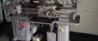
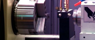
Screw-cutting
Screw cutting machines have high rigidity and precision in processing the workpiece. Their bed, as a rule, is monolithic, and the headstock is massive and has increased rigidity (capable of withstanding high pressure).
The spindle of such a machine is mounted on high-precision bearings (class “P”, not lower). The caliper carriage has a more elongated shape (on guides), and the caliper itself has no rotating parts.
The lead screw on a metalworking screw-cutting machine has a large diameter, and in addition, it is mounted on roller bearings. As a result, it is ensured:
- smooth movement of the caliper carriage;
- quite a large force even at low speed of movement of the caliper;
- The skew of the carriage is completely eliminated (due to the location of the lead screw between the guides).
Taken together, these measures make it possible to cut threads according to specified parameters with high accuracy.
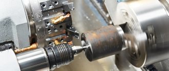
Automatic and semi-automatic machines
In modern conditions, more and more metal-working turning equipment is produced in automatic form. This is dictated by the need to increase productivity.
Automatic machining turning centers completely eliminate any actions (manipulations) involving humans (including inserting and removing a workpiece into a chuck, as well as changing the cutting tool).
However, such centers are quite expensive, so in cases where high productivity is not required, semi-automatic machines are used, in which all options are automated, except for positioning and strengthening the workpiece and tool.
Lobototurn
A metal-cutting lathe is designed primarily for processing the end side of a workpiece. It does not have a tailstock and is designed for workpieces whose diameter significantly exceeds their height. Lobe lathes are often equipped with turret supports for the convenience and speed of tool changing.
Milling
We are not talking about milling machines, but about turning and milling machines. The main characteristics of such equipment is the ability to perform both turning operations:
- groove;
- drilling;
- cutting, etc.
So is milling the workpiece:
- formation of profile surfaces;
- cutting straight and curved grooves and grooves;
- more efficient trimming.
Such versatility is achieved thanks to the presence of a milling part with a second spindle. Turning and milling machines are used in watchmaking, tool production and other industries where optimization of the workpiece reinstallation process is required.
Longitudinal turning
A special feature of such machines is that the cutting tool can only perform transverse movement. And the longitudinal movement relative to the support is produced by the workpiece itself, fixed in the spindle.
Rigid attachment of the cutter (that is, precisely in the processing zone) allows for high processing accuracy. In addition, the advantages of this type of lathe are:
- possibility of turning workpieces with complex shapes;
- ability to work with workpieces of small sizes and shapes; high rotation speed (up to 6 thousand revolutions per minute) gives
- the ability to achieve high processing accuracy (up to 0.005 mm).
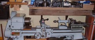
Tabletop
This type of equipment is intended for small industries (for workshops, for handicraft production). They are characterized by increased precision of workpiece processing and low productivity.
But in a workshop, high quality turning is in demand much more often (and it is more urgent) than the possibility of continuous production is realized.
Such machines, as a rule, have a low cost, compact size, and low noise level. Parts and components for such machines (guides, bearings, etc.) are manufactured with a high level of precision.
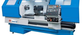
Modern CNC
Here we are not even talking about individual machines, but about entire turning machining centers. Equipment with numerical control is capable of performing all possible operations with it in one installation of a workpiece, processing several surfaces at once. The characteristic features of such centers are:
- carrying out processing in a closed chamber, without human participation and control;
- cutting tools are replaced automatically;
- the human factor comes down to the competent development of a virtual drawing - a CAD model of the required part.
And then you just need to place the workpiece in a special box and pick up the finished part.
With continuously variable drive
A continuously variable drive is used to smoothly and non-stop change the rotation speed of a machine spindle or feed mechanism.
A continuously variable drive can be compared to a CVT transmission in a car transmission.
As a result, with the help of smooth control it is possible to obtain the most advantageous (from the point of view of ensuring the quality of processing) processing speeds of the workpiece or movement of the cutting tool in the support.
In addition, the time spent in classic machines on stopping the spindle to change the rotation speed of the chuck is saved. The advantages of such equipment are obvious:
- Durability of the machine drive due to the absence of a gearbox.
- Since there are no whole complicating units, it is very simple to carry out maintenance of such machines.
Pipe cutting
There are pipe cutting machines with one or two chucks for positioning the workpiece being processed (depending on the expected size of the workpiece itself). The main functionality of such machines is:
- processing of pipe ends;
- thread cutting;
- forming locking threads on adapters and drill pipes.
These machines are most in demand in the oil industry for pipe preparation and pipeline repair. In addition, pipe cutting lathes are widely used in mechanical engineering.
Slotting, planing, broaching. Other machines. Groups 7, 8, 9
- 7210
longitudinal planer Ø 900 x 1000, Minsk - 7212
longitudinal planer Ø 1120 x 1250, Minsk - 7216
longitudinal planer Ø 1400 x 1600, Minsk - 7A33
cross-planing Orenburg - 7B35
cross-planing Orenburg - 7D36
cross planer Gomel - 7D37
cross planer Gomel - 7E35
cross planer Orenburg - 7M36
cross planer Gomel - 736
cross-planing Orenburg - 737
cross planer Gomel - 7303
cross-planing Orenburg - 7305
cross-planing Orenburg - 7307
cross-planing Orenburg - 7307G
cross planer Orenburg - 7307D, 7310d
cross planer Gomel - 7A412
slotting Ø 360, Saraktash - 7A420
slotting Ø 500, Saraktash - 749
cross-planing Orenburg - 7402
Slotting Orenburg, Baku - 7410
Slotting Minsk, MZOR - 7430
slotting Ø 650, Gomel - 7D430
slotting Ø 630, Gomel - 7D450
slotting Ø 800, Gomel - 7M430
slotting Ø 630, Gomel - 7403, 7405
— slotting Ø 630, Gomel - 7417
Slotting Orenburg - GD200
slotting Ø 500, Gomel - GD320
slotting Ø 770, Gomel - GD500
slotting Ø 940, Gomel - 7A510
broaching 98 kN, Minsk - 7B510
broaching 100 kN, Minsk - 7A534
broaching 250 kN, Minsk - 7B55
broaching 100 kN, Minsk - 7B56
broaching 200 kN, Minsk - 7523
broaching 100 kN, Minsk - 7534
broaching 250 kN, Minsk - 8A531
vertical band saw Maikop - 8A725
automatic hacksaw-cutting machine Leninakan - 8B72
cut-off saw Ø 250 Krasnodar - 8B66
automatic cutting circular saw Ø 280, Minsk - 8В66а
automatic cutting circular saw Ø 280, Minsk - 8G240
abrasive cut-off Ø 60 - 8G662
automatic cutting circular saw Ø 280, Minsk - 8G663
automatic cutting circular saw Ø 285, Minsk - 872A
cut-off saw Ø 250 Krasnodar - 872M
cut-off saw Ø 250 Krasnodar - 8535
band saw Ø 350 Kuvandyk - 8725
hacksaw Ø 250 Orenburg - N-1
hacksaw Ø 250 Kaunas
7.1. Longitudinal planing machines, single and double column
7.3. Cross planers
7.4. Slotting machines
7.5. Horizontal and vertical broaching machines
Cutting machines
Design Features
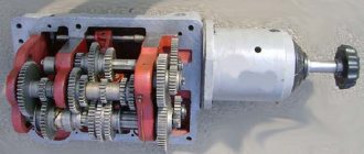
Regardless of the specialization, automation and purpose of lathes, they all have the same components and elements, which makes their design largely universal, and the components interchangeable:
bed
The most massive part of the machine. It is the basic basis for installing all other components on it. The tasks of the bed include:
- ensuring the rigidity of the entire machine structure as a whole;
- concentrating on yourself and extinguishing all arising vibrations.
The bed, as a rule, is cast from cast iron and made monolithic.
However, there are options for a lightweight frame made of profiled pipes (square section). Such machines are installed on vibration supports.
Apron
This is a carriage that moves along guides (under the influence of a lead screw), on which the caliper is rigidly fixed. In addition to automated movement, the apron can also be equipped with a manual drive.
Headstock
Another name for it is the headstock. This is the part of the machine in which the gearbox is located and where the main shaft with a spindle (hence the name) is attached, in which the workpiece is mounted.
Caliper
This is a structural element of a lathe, located on the apron. On the support, in turn, there are tool holders, where the cutting tool is strengthened. Usually they talk about transverse or longitudinal movement not of the cutter or apron (respectively), but of the support.
Gearbox
Structurally, it is located in the headstock. The front panel has speed switch knobs. If the machine is not equipped with a continuously variable drive, then in order to change the gear (that is, the speed of rotation of the workpiece and the force on the shaft), you must first turn off the machine and wait until the main shaft stops.
Electrical part
This structural element includes a traction motor, as well as other electrical equipment with which the machine is controlled.
FLEXIBLE PRODUCTION SYSTEMS
A production system is a group of machines that sequentially process one workpiece. For mass production of, for example, automobile parts, specialized production systems called automatic lines are used. Such a line consists of separate machines (milling, drilling, boring), interconnected by a system for moving parts from one machine to another. Automatic lines make it possible to reduce the cost of mass production of similar parts.
However, in mechanical engineering, serial and individual production predominate, requiring frequent re-adjustment of equipment. The use of conventional automatic lines in such production is ineffective. The basis of integrated mechanization here is group technology, CNC machines, industrial robots, and automatic transport and storage systems. On their basis, with the use of coordinating computers, quickly reconfigurable automated complexes are created, called flexible production systems (GPS). In the production of, for example, diesel engine cylinder heads, the GPS is capable of processing cylinder heads from 5 to 100 different sizes and types, and their blanks can arrive in a random order.
Main technical characteristics
All lathes of the turning group differ from each other in the following technical parameters:
- maximum spindle speed (the higher it is, the better the quality of surface treatment, the higher the cleanliness class);
- force on the shaft in various gears (this parameter depends on the power of the traction motor, so it is customary to talk about the total power of the machine);
- the maximum diameter of the workpiece being processed (the digital parameter in this case is an indicator of the height of the centers of the machine - the clamping points of the workpiece;
- an indicator of what type of machine it is (screw-cutting, turning-milling, face-to-face, etc.);
- presence and degree of automation (determined by the presence and “advancement” of a numerical control module).
In general, the main technical characteristics of a lathe can be gleaned from the markings on its nameplate (see the section “Notation systems and decoding”).
1.3. Division of machines according to their masses
- Lightweight machines:
weight up to 1 t - Medium machines:
weight from 1 t to 10 t - Large machines:
weight from 10 t to 30 t - Heavy machines:
weight from 10 t to 100 t - Particularly heavy machines:
weight over 100 t
The technical characteristics of some heavy machines also contain the largest workpiece mass.
Accuracy indicators. The accuracy of metal-cutting machines is determined by three groups of indicators: characterizing the accuracy of processing of product samples; characterizing the geometric accuracy of machine tools; additional.
Indicators characterizing the processing accuracy of product samples include:
- accuracy of geometric shapes and location of processed surfaces of product samples;
- constancy of batch sizes of product samples;
- roughness parameters of processed surfaces of product samples.
Indicators characterizing the geometric accuracy of the machine include:
- accuracy of bases for installing workpieces and tools;
- accuracy of movement trajectories of the working parts of the machine, carrying the workpiece and tool;
- the accuracy of the location of the axes of rotation and the directions of linear movements of the working parts of the machine, carrying the workpiece and the tool relative to each other and relative to the bases;
- accuracy of interconnected relative linear and angular movements of the working parts of the machine, carrying the workpiece and tool;
- accuracy of dividing and installation movements of the working parts of the machine;
- accuracy of coordinate movements (positioning of the working parts of the machine) carrying the workpiece and tool;
- the stability of some parameters with multiple repetitions of the test, for example, the accuracy of approach to a hard stop, the accuracy of small approach movements.
Additional indicators of machine accuracy include the ability to maintain the relative position of the working parts of the machine carrying the workpiece and tool, provided:
- external load applications;
- exposure to heat generated when the machine is idling;
- machine vibrations that occur when the machine is idling.
General safety instructions
Let's divide the safety rules into 2 large sections:
What should the machine operator do:
- The operator's clothing must be fastened with all buttons while operating the machine. There should be no loose laces. (Probably everyone remembers the humorous warning poster: “To prevent the shaft from getting twisted, roll up your sleeve...”).
- Before turning on the machine, a technical inspection should be carried out.
- All actions on the machine must be performed only in accordance with the detailed technological process of processing the workpiece.
It is strictly prohibited:
- start work during inspection and adjustment of the machine;
- operate the machine with significantly worn centers; use as little as possible, but a defective cutting tool;
- in the absence of proper qualifications, try to correct problems in the electrical equipment of the machine;
- move away from a working machine or entrust work on it to third (untrained) persons.