Automation of production has greatly expanded the capabilities of industry. Automatic devices and CNC systems not only allow routine and cyclic work to be performed without human intervention, but also significantly increase the speed, accuracy and capabilities of the actions performed.
The basis of any production process is the CNC device. In industry, most functions are performed by machines. The CNC device in them is the basis of production. Along with automatic conveyor belts and industrial belts, modern CNC systems for machine tools have taken production to a whole new level.
A little history
However, the modern stage in the history of CNC machines began only a century and a half after the invention of Jacquard, in the United States of America. After the end of World War II, in the late 40s, John Parsons, the son of the owner of Parsons Incorporated, tried to control the machine using a special program that was entered from punched cards. Parsons did not achieve any positive results, so he turned to specialists at the Massachusetts Institute of Technology for help.
The employees of the institute's laboratory of servomechanics did not improve the design presented to their attention, and they quickly forgot about Parsons. But about his ideas - no. Having created their own design, they initiated the institute’s purchase of a company that produced milling machines. After which the leadership of the Massachusetts Institute of Technology entered into a contract with the US Air Force. The contract dealt with the creation of a new type of high-performance machines for processing propellers by milling.
The operation of the milling machine, which was assembled by the laboratory staff in 1952, was controlled according to a program read from a punched tape. This design turned out to be too complex, and the desired result was not achieved. However, the story became public, information about the new development was published and aroused great interest from competitors. Several well-known companies simultaneously began their developments in this direction.
The greatest success was achieved by the designers of Bendix Corporation. The NC device released by Bendix has been in production since 1955 and has already been actually used to control the operation of milling machines. The new product took root with difficulty, but thanks to the interest and financial assistance of the military department, over two years more than 120 CNC machines were produced, which significantly increased labor productivity and the accuracy of machine work.
Even then, the undeniable advantages of the NC numerical control system for machine tools were noted: a significant increase in labor productivity and significantly higher precision of surface processing. But truly revolutionary changes in the field of CNC machines took place when specially designed microprocessors and microcontrollers were used as a “smart” module that controls the operation of the machines. The technical term “CNC”, which began to designate these systems abroad, is an abbreviation of the English words ComputerNumericalControl.
NC is not Norton Commander
Studying the history of improving “smart” CNC machines, which were once denoted abroad by the abbreviation of the Latin letters “NC,” students of past years often confused this concept with a computer shell program that was popular in those years. In fact, the abbreviation NC comes from the English words NumericControl. Numerical control was then very primitive, and the machine program could look like a lot of special plugs located on a contact pad.
By the way, one of the first Soviet transistor computers for engineering calculations, “Promin,” which appeared in the early 60s of the last century, was programmed in a similar way. At that time, the control module of the CNC machine could not properly respond to deviations of the processing process from the calculated one, if such a situation occurred. Control adaptive microprocessor systems appeared much later.
Over time, as electronics and computer technology improved, “thinking” control modules on microprocessors and microcontrollers were added to help the new generation of machine tools. So they were able to provide flexible, multi-variant control of the cutting process. And not only this. Such systems received the more sonorous title “CNC”, which in English sounds like ComputerNumericalControl. Our term CNC turned out to be more universal and did not have to be changed.
Classification of modern CNC systems
Control systems and machine tools with numerical software are so complex that they cannot be classified according to any one criterion. The main characteristics of CNC systems allow us to systematize them as follows:
1.Depending on the method of controlling the actuators of the machine:
● Positional . Here, the tool, in accordance with the CNC program, moves from one point at which the necessary operation with the workpiece is performed, to another, where processing is also performed. While the tool is moving, no other operations are performed.
● Contour, in which processing can be carried out along the entire trajectory of the tool.
● Universal – CNC systems in which both control principles can be used.
2.According to capabilities and method of positioning:
● Absolute reference – the location of the moving mechanism of a CNC machine is always determined by the distance from the origin of coordinates.
● Relative counting during positioning is carried out by incrementing an additional path to the coordinates of the previous point, which is temporarily taken as the origin of coordinates. The origin of coordinates is then considered to be the next point reached.
3. Based on the presence or absence of feedback in the CNC control loop:
● Open – (“open” type). The movement of the actuators is carried out according to the commands contained in the program. There is no information about the coordinates actually reached.
● Closed type (closed). In CNC systems of this type, the position coordinates of the actuators are constantly monitored.
● Self-adjusting (“closed” with increased accuracy). A more advanced system that remembers incoming information about the discrepancy between the specified and actual coordinates of the actuator, processes it, and adjusts new commands taking into account changed conditions.
4.Generation. Depending on the technical level of the microprocessors, microcontrollers or control PCs used, CNC systems of the 1st, 2nd and 3rd generation are distinguished.
5. Number of coordinate axes . Various machines equipped with CNC can support operating modes with different numbers of coordinate axes - from two to five. For example, if when a workpiece moves on a milling machine (3 coordinates - X, Y, Z), it can simultaneously rotate around its axis, such a machine is called 4-coordinate. The simplest drilling and single-support lathes have two coordinate axes.
The following features of linear modules can be distinguished:
- High levels of accuracy and reliability.
- This ensures that no play occurs under load. To achieve this effect, cylindrical guides are used on the support.
- The rigidity of the structure is achieved by using carriages with adjustable tension of linear bearings.
- The ball screw allows you to obtain the required torque while cutting the workpiece.
The axle is mounted on opposing angular contact bearings. Mounts for standard stepper motors are used.
His Majesty the computer needs a program
Unlike a standard personal computer, which is a universal device for processing information and is capable of working with any data presented in digital form, the microprocessor used in the design of many CNC machines is a specialized device. It does not contain anything superfluous, and its entire set of functions is designed to perform the main task - monitoring the state of all executive bodies of the machine and controlling their work according to a special program. To control particularly complex modern machines, more productive and multitasking devices are used - industrial computers.
One of the most important characteristics that allows us to judge the performance and technical capabilities of the machine and the system that controls its operation is the number of “axes”. In other words, channels of interaction with the object, controlled parameters. However, in any case, regardless of the microprocessor of what level of complexity and architecture is installed in a given control controller, a previously prepared program is needed for its operation. In which all actions of the CNC machine mechanisms necessary for the manufacture or processing of the required part must be accurately and consistently described.
When operating CNC machines, two types of programs are used:
● System (utility) programs that are stored in ROM (read-only memory of the system). They provide the initial stage of operation of the controller after switching on, are responsible for setting up the machine and the entire CNC system, its ability to understand operator commands and interact with external devices.
● Controllers – external programs. Contain a set of commands and instructions for the executive bodies of the machine. Control programs (CP) can be entered into the controller step by step by the operator, input from external storage media is possible, and in modern systems programs can come directly from the computers of software developers through the enterprise computer network.
Having replaced a person who, before the era of CNC machines, successfully coped with the production of the necessary parts, a programmable control unit, also known as a controller, must provide the required result, step by step turning on and off the movement mechanisms of the table, workpiece and tool magazine, changing rotation modes or speed translational movement of the workpiece. As a result of executing the program, a part should be obtained that fully corresponds to the specifications in terms of size and surface finish.
The companies that were at the forefront of the development and production of CNC systems initially programmed their machines using their own specially designed commands. If, with this approach, CNC machines from different manufacturers were put into production, preparing programs for their operation would be a difficult task. To try to ensure software and technical compatibility of equipment from different brands, the language for creating programs for CNC machines was unified.
The basic control code for preparing programs was a set of commands developed by specialists from the Electronic Industries Alliance in the 60s of the last century. This is the so-called “G” and “M” code language, which is more often called simply G-code. The designations of preparatory and main functions adopted in this language begin with the Latin letter “G”, and the designation of additional – technological commands – with the letter “M”.
Review of the most interesting models
Currently, the leading foreign manufacturers of CNC metalworking centers are Takisawa, DMTG, Yamazaki, Mazak, Trens, Milltronics, Ming Yang Machinery, Long Chang Machinery, HJM Machinery. In Russia - Ivanovo Heavy Machine Tool Plant, Sterlitamak Machine Tool Plant, Ryazan Machine Tool Plant, Vladimir Machine Tool Plant.
If we talk about the universal turning and milling type, then one of the best manufacturers here is Takisawa (Japan) with a series of LA and EX centers. The unique feature of these centers is that they are easy and convenient to carry out both turning and milling operations. Excellent for small-scale and mass production. Allows you to significantly reduce production costs.
These units come standard with: – direct drive spindle for high-performance machining; – built-in cooling; – oil cooling; – counter spindle with a fully functional “C” axis; – 3-jaw hydraulic chuck; – drives and Fanuc CNC system (very stable and reliable, recognized by most manufacturers); – disc braking system, etc.
Some of the best milling machining centers in the world are produced by DMTG (China). The VDL series of vertical milling units are relatively inexpensive, compared to analogues, and at the same time multifunctional centers.
Being the cheapest option for 3-axis (4-axis) machining of body parts, the machines are capable of performing a variety of milling operations.
The standard equipment of the machining center includes: – tool magazine; – optical rulers; – guides.
Distinctive features of these installations: – high rigidity and stability; – high-precision guides on all three axes of the machine; – high speed and accuracy of the spindle; – speed and reliability of the tool changing system; - cooling system; – multifunctional Fanuc CNC system.
Among horizontal metalworking centers, it is worth paying attention to installations from Milltronics (USA).
Models are equipped with engines of varying power. The transmission of rotation from the motor to the spindle is carried out by direct drive, belt drive or gearbox. Bed – cast iron, cast. It is made with additional ribs that give the structure increased rigidity.
The main application is processing of body parts. If you equip the center with a 4th axis, this will allow you to perform multi-position processing in one installation. This improves processing quality and productivity.
Models are equipped with a wide range of additional options. Among them are automatic tool change, rotary table, spindle with a rotation speed of up to 15,000 rpm. etc.
Domestic manufacturers also produce good installations. For example, turning and milling machining center model 500HS of the Sterlitamak Machine Tool Plant (Russia). The installation with automatic tool change is designed for processing workpieces made of different structural materials. Excellent for both single production and small-scale, serial production.
The machining center is capable of performing external and internal turning, drilling, countersinking, reaming, semi-finish and fine boring of holes, threading with taps and cutters, and milling.
Another model 800VHT of the Sterlitamak plant is a purely turning type installation. Main purpose: combined processing of parts of varying complexity in a contour version.
It is impossible not to mention the universal turning and milling super-center IS800 “Globus” of the Ivanovo Heavy Machine Tool Plant (Russia).
The 5-axis high-speed machine is used for machining highly complex parts. These are blades, impellers and other products used in the aerospace and aviation industries.
The main distinguishing feature of this machining center from the basic models is the presence of a rotary table. Together with a number of innovative solutions, the Ivanovo plant installation can perform a very large amount of work in a short period of time.
"G" and "M" codes in programs for CNC machines
According to the standard, all commands whose code begins with the letter “G” are intended for linear or circular movement of the working parts of the CNC machine, performing certain sequences of actions, tool control functions, changing coordinate parameters and the reference plane. The command syntax usually consists of the name of the G-code, coordinates or addresses of movements (X, Y, Z) and the specified speed of movement of the working body, denoted by the letter “F”.
The CNC command can include a parameter describing the duration of the pause, the so-called dwell time – “P”, an indication of the spindle rotation parameters – “S”, the radius value – “R”, the tool correction function – “D”, as well as the arc parameters “ I", "J" and "K".
For example: G01 X0 Y0 Z110 F180; G02 X20 Y20 R5 F 200; G04 P1000 .
In the first example, the G01 code stands for “linear interpolation” - linear movement at a specified speed (F) to a given point with coordinates (X,Y,Z). The second example specifies G02, which describes arcuate motion (circular interpolation). In this case, the code G02 corresponds to movement in the direction of rotation clockwise, and its antipode G03 - counterclockwise. The third example contains command code that describes the delay time in milliseconds.
Technological commands, designated by the letter “M”, are responsible for turning on or off certain CNC machine systems, changing tools, starting or ending a special subroutine, and other auxiliary actions.
For example: M3 S2000; M98 P101; M4 S2000 M8.
Here, in the first example, a command is indicated to start spindle rotation at speed “S”. The second contains an order to call the specified subroutine “P”. The third example describes the command to turn on the main cooling (M8) when the spindle rotates at speed (S) in a counterclockwise direction (M4).
Modernization
Industrial development forces even ultra-modern machining centers to modernize. This concerns, first of all, increasing accuracy and productivity while maintaining the rigidity of the entire structure.
Dozens of additional options appear. For example, installing an automatic bar feed and a part catcher allows you to make the process of turning small workpieces completely automated. Installing an additional spindle in place of the tailstock will help increase productivity. Thus, the second end of the workpiece can be processed without rearranging it in the machine.
A very useful option is the ability to position the spindle along the C axis with the installation of a tool rotation drive. This makes it possible to drill and tap threads on the sides of the part. And milling of complex curves on the side surfaces is carried out by setting the head to move along the Y axis.
In general, machining center manufacturers are increasingly striving to create highly targeted installations. That is, with technological capabilities for a specific industry. Thus, along with turning and milling centers, equipment of milling and turning types is produced separately.
Methods for creating and structure of control programs
Modern equipment allows you to create programs for operating CNC machines in several ways:
● Writing a program manually or in a PC text editor. A necessary stage in training specialists to work on CNC machines. It is also suitable as the main method of programming in factories where several simple parts are produced over a long period of time without resorting to restructuring the equipment.
● Drawing up and entering a program on the CNC rack. The control panel of most modern control systems contains a keyboard and display, which allows you to program and view a virtual simulation of the machining process directly at the workplace. Many systems allow you to enter programs in the “background” while the machine is busy processing a given part.
● Using the capabilities of CAD-CAM systems for computerized production preparation. Special software allows you to create a three-dimensional model of a part, calculate and prepare a program for its production. And also virtually “manufacture” the required part, using real data on the kinematics of a specific CNC machine. This method allows you to create control programs quickly and accurately, practically eliminating programming errors and associated damage to workpieces. The effectiveness of this method is especially high when creating CP for the manufacture of particularly complex parts.
Structurally, a G-code program consists of blocks. This is the name given to groups of commands that are intended to perform some completed action. Personnel can also consist of one team. The end of each “frame” is indicated by the line feed (LS/LF) character. Each program begins with an empty “frame”, which consists of the “%” sign, and ends with codes M02 or M30, respectively indicating the end of the CNC program or the end of the information block in memory.
The specified structure and language for preparing programs for CNC equipment are enshrined in international standards RS2740, ISO-6983-1.82, as well as GOST USSR 20999-83. Domestic specialists often use the designation “ISO-7 bit”, which has been assigned to G-code programs since the times of the USSR. Programmers of companies that develop and produce CNC machines are required to adhere to the requirements of world standards when preparing software.
In some cases, when developers provide their systems with additional capabilities and some special functions, there may be certain deviations of the software from the standard for creating programs in G and M codes. In such cases, you should carefully study the documentation that should be provided by the equipment manufacturer.
Lathes
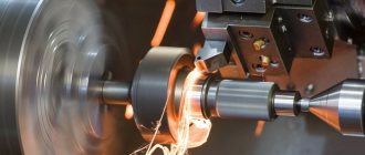
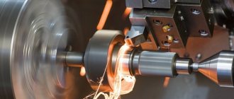
There are a large number of CNC-equipped processing devices. Semi-automatic units have a lower cost than their automatic counterparts . But they require periodic operator intervention and are not capable of producing parts autonomously. Automatic machines are capable of producing in large volumes, but not everyone can afford them.
The most popular and high-quality models are those produced by the following companies:
- CNC (manufactures multifunctional devices);
- Victor (manufactures high-performance mechanisms with additional capabilities);
- MetalMaster (manufactures units equipped with an automatic lubrication system that can handle tough materials).
When using lathe equipment, safety precautions must be followed.
