According to the classification of installations for cutting various types of threads, the 1E61M lathe belongs to the high-precision group of similar equipment. If you make a complete setup and adjust in detail each parameter of the node modules, the performance, accuracy and functionality of this machine will significantly increase. In skillful hands, the machine can cut almost any type of thread.
Model modifications
The standard model 1E61M was modernized and released in several variations. Each modification of the machine has its own characteristics in terms of operations and quality of work.
1E61M
The addition of the "M" symbol means that the machine has increased accuracy. This modification is used for roughing and finishing machining of workpieces.
1E61MT
This is a high-precision unit that is used exclusively for finishing operations.
1E61MS
Another modification of the standard equipment 1 E61M. It is also used for finishing blanks and for thread cutting.
Technical characteristics of the use of screw-cutting lathe
The technical characteristics of a lathe determine the capabilities of the master when carrying out turning operations. The main characteristics of the equipment under consideration are as follows:
- the maximum diameter of the workpiece that is processed above the bed is 32 cm;
- the same indicators above the caliper – 18.8 cm;
- the diameter of the rod that goes into the spindle is 32 mm;
- the maximum length of the installed RMC part is 71 cm;
- spindle speed – 35-1600 rpm.
The maximum stroke length of the caliper for longitudinal movement of the carriage is 64 cm. For transverse movement of the carriage – 20 cm.
1E61M High precision screw-cutting lathe. Passport, diagrams, characteristics, description
Manufacturer of the high-precision screw-cutting lathe 1E61M - Ulyanovsk Machine-Building Plant named after. Volodarsky is a multidisciplinary enterprise that produced cartridges for rifled small arms, automobile spark plugs, screw-cutting machines, lifting equipment, automatic rotary lines, contactless starters, saw chains, traction, drive, roller chains, spare parts for agricultural machinery and consumer goods.
The plant produced universal screw-cutting lathes of the following models: TV-01, TV-01M, 1E61, 1E61M, 1E61MT, 1E61VM, 1E61PM, S1E61VM, S1E61PM, UT16VM, UT16PM, UT16VMT, UT16PMT, UT-320.
Machine tools produced by the Ulyanovsk Machine-Building Plant named after. Volodarsky
Lathes models 1E61M are created on the basis of the TV-01M machine and belong to the class of light lathes. The beginning of serial production of the 1e61 machine was in 1965. Production of the next model 1E61PM, 1E61VM began in 1975.
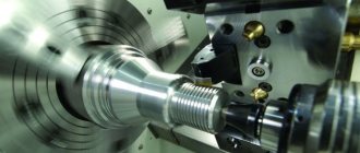
The screw-cutting lathe model 1E61M is universal and is designed to perform finishing operations when turning high-precision parts and cutting various threads. Machine accuracy class - P.
Smooth cylindrical surfaces are ground when securing the workpieces in a three-jaw chuck with a through cutter.
Cylindrical boring is the cutting of a pre-drilled or unmachined hole with a boring tool.
Trimming, grooving and cutting are carried out to give the workpiece a certain Shape, size and roughness.
External grooves are machined with slotted cutters. Cutting is carried out using cutting tools.
Machining of external conical surfaces, depending on the length of the conical part and the angle of inclination of the conical surface, can be turned with a wide cutter, turning the slide of the upper longitudinal support, transverse displacement of the tailstock body using a copy-cone ruler.
Hole processing. On a lathe you can drill and process holes (drill, ream, countersink, perform cylindrical and conical boring).
Description of the design of a screw-cutting lathe
The machine is driven by an individual electric motor with a power of 4.5 kW and a speed of 1335 revolutions per minute.
The movement is transmitted to the receiving pulley of the gearbox by a V-belt drive. From the gearbox, six V-belts transmit the movement further to the headstock pulley, and then, using a toothed coupling, to the spindle.
High precision threading is provided by the ability to connect the lead screw directly to the corresponding set of replacement gears on the guitar, bypassing the entire feed chain.
The machine also allows you to cut threads of normal accuracy using a feed box.
The feed chain of the machine has a pitch increasing link, through which an eightfold increase in the table value of feeds and thread pitches is achieved.
By turning on the step increasing link, you can cut steep threads, cut all kinds of steep spirals, cut multi-start worms and perform a number of special jobs.
The machine apron has a “falling” worm mechanism that automatically turns off longitudinal and transverse feeds when working with fixed stops. At the same time, this mechanism protects the machine from damage due to overload. But when working with a lead screw, it is unacceptable to use a longitudinal stop.
In the middle part of the spindle head there is a wedge drive pulley mounted on two ball bearings. Thus, the spindle is relieved from the tension of the V-belts.
The headstock is automatically lubricated by a separate oil pump. The switching on of the main electric motor and the switching on of the oil pump are interlocked, which eliminates the possibility of the spindle head operating without lubrication.
The supply of cutting fluid to the cutting zone is carried out by an electric pump, which is turned on as needed from a separate switch.
Reversing the main movement of the machine is electrical. The spindle rotation is braked by countercurrent in the electric motor.
The high-slip electric motor used on the machine ensures an increase in the reversing frequency when cutting threads.
The production capabilities of the machine are significantly expanded with the help of a number of additional accessories included with the machine upon special order at an additional cost.
The machine provides high accuracy subject to the following points:
- Do not install the machine near impact machines or machines that cause external vibrations.
- The machine should be installed in a clean, bright room, but at the same time it should be protected from direct sunlight.
- Do not install the machine near heating appliances.
- The room temperature should be maintained within 18-20° C.
Dimensions of the working space and connecting bases of the 1E61M screw-cutting lathe
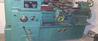
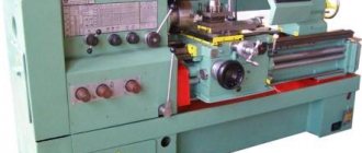
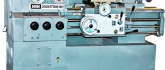
1E61M General view of the universal screw-cutting lathe model
1E61M Location of the main components and controls of the machine
List of controls for the 1E61M lathe
- Turning on the electric oil pump and connecting to an external power supply
- Switching on the emulsion electric pump
- Stop for starting, stopping and reversing the spindle
- Stop for starting, stopping and reversing the spindle
- Switching spindle speeds
- Enabling headstock override
- Snaffle and mechanism for eightfold increase in thread pitches
- Shifting Norton Cone Gears
- Inclusion of metric and modular, imperial and pitch or precision threads
- Multiplying mechanism for feeds or thread pitches
- Turning on the lead screw or lead shaft
- Handwheel for manual longitudinal movement of the carriage
- Moving the cross slide
- Moving the upper caliper slide
- Fastening the cutting head
- Enabling longitudinal or transverse feeds
- Engaging the lead screw nut
- Turning on and off the falling worm
- Attaching the support carriage to the frame
- Attaching the tailstock to the frame
- Moving the tailstock quill
- Tailstock quill fastening
- Transverse displacement of the tailstock housing
- Automatic stop for longitudinal feed
- Automatic cross feed stop
- Rigid fixation of the lead screw nut
- Turning on local lighting
- Quick removal of the cutter from the workpiece
Main components of a lathe, controls and their purposes
The source of movement in the machine is an electric motor, which transmits rotation to the spindle through a gearbox (gearbox), and from the spindle through a set of replaceable gears and a feedbox, rotation is transmitted to the lead screw m (for thread cutting) or to the run shaft N (for other turning operations). operations).
Spindle braking is carried out countercurrently.
The short workpieces are clamped in the jaw chuck, and the right end of the long workpiece is supported by a center located in the tailstock quill.
The tailstock is also used to secure and feed drills and other axial tools.
The support serves to carry out movements of the cutter fixed in the tool holder in the longitudinal and transverse directions.
The apron mechanism converts the rotational movement of the lead shaft or lead screw into the translational movement of the caliper.
1E61M Kinematic diagram of a screw-cutting lathe
Kinematic diagram of a 1E61M screw-cutting lathe. View enlarged
1E61M Location of gearbox control handles
Purpose of lathe gearbox control handles
- Norton cone handle
- Guitar
- Headstock
- Inch and pitch threads
- Metric and modular threads
- Precise threads
- Multiplier feed handle
- Roller
- Lead screw
- Shift knob
- Tuning knob
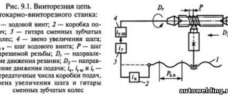
1E61M Guitar tuning diagram (longitudinal and transverse feeds)
Guitar tuning diagram of a lathe
- a) Tuning the guitar for precise, normal, metric and modular threads
- b) Tuning the guitar for normal, inch and pitch threads
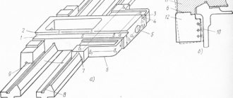
1E61M Headstock of screw-cutting lathe
Features of disassembling and assembling the 1E61M machine during repair
When disassembling the machine for repairs or other reasons, pay attention to the following:
- Disconnect the machine from the electrical outlet before disassembling it.
- disconnect the injection 3 and drain 13 tubes from the oil system (Fig. 21)
Before removing the spindle head from the machine, you must:
- remove the V-belts from the gearbox pulley
- unscrew the four Ml4 bolts securing the spindle headstock to the bed (two bolts are located inside the housing at the rear of the headstock)
- remove the headstock from the bed
To remove the headstock V-belts, you need to remove the headstock spindle, and then the hub with the pulley sitting on it.
To remove spindle 1 from the headstock housing, it is necessary to remove the top cover 24, the rear covers 12, 13 and the front flange 2. Together with the rear cover, remove the snaffle shaft 8. Unscrew the nut 10 from the end of the spindle, first loosen the screw 11. Then loosen the nut 3 , and by screwing nut 23 onto bushing 25, loosen liner 26, thereby increasing the gap between the spindle and the liner. Do the same with the rear plain bearing. Then unscrew the locking screws of the snaffle gears 15 and the gear 4. Then, using a lead hammer, knock out the spindle with gentle blows.
To remove the pulley with the hub from the headstock housing, it is necessary to remove the rear flange 14, loosen the locking screw 6 and unscrew the nut 7, then remove the snaffle 9. Next, you need to loosen the locking screw 20, unscrew the nut 21, loosen the set screws 19 and 16. After this, use blows knock out hub 18 together with pulley 17 into the end of selector gear 22.
Remove the rubber drain pipe 5 and remove the V-belts. Reassembling the headstock will occur in the reverse order.
Disassembly of the remaining components of the machine, due to the clarity of dismantling, does not require explanation.
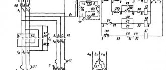
1E61M Electrical circuit of a lathe
Electrical equipment of the machine
The machine is equipped with 3 three-phase squirrel-cage asynchronous electric motors for voltage 220/380 V:
- D1 - main electric motor type AOS 51/4, version Shch-2, power 4.5 kW, 1335 rpm
- D2 - electric lubrication pump type PA-22 with a power of 0.125 kW, 2800 rpm
- D3 - electric coolant supply pump type PA-22 with a power of 0.125 kW, 2800 rpm
The electrical equipment of the machine is mounted at a voltage of 380 V.
If necessary, a machine with electrical equipment for a voltage of 220 V can only be made upon special order.
1E61 High precision screw-cutting lathe. Video.
Parameter name 1E61M 1E61MT 1E61PM UT61PM
| Basic machine parameters | ||||
| Accuracy class according to GOST 8-82 | P | IN | P | P |
| The largest diameter of the workpiece processed above the bed, mm | 320 | 320 | 320 | 320 |
| The largest diameter of the workpiece processed above the support, mm | 188 | 188 | 170 | 170 |
| Maximum length of the installed RMC part, mm | 710 | 710 | 710 | 750 |
| The greatest distance from the axis of the centers to the edge of the tool holder, mm | 185 | 185 | 175 | 175 |
| Distance from the spindle axis to the bed guides (height of centers), mm | 170 | 170 | 175 | 175 |
| Spindle | ||||
| Spindle hole diameter, mm | 32,5 | 32,5 | 30 | 32 |
| Diameter of the rod passing through the hole in the spindle, mm | 32 | 32 | 25 | |
| Spindle speed, rpm | 35..1600 | 35..1600 | 35,5..1800 | 40..2000 |
| Number of forward/reverse spindle speeds | 12 | 12 | 18 | 18 |
| Center in the spindle according to GOST 13214-67 | Morse 5 | Morse 5 | Morse 5 | Morse 5 |
| Spindle end according to GOST 12595-72 | 5K | 5K | ||
| Spindle braking | There is | There is | There is | There is |
| Spindle lock | There is | There is | There is | There is |
| Spindle overload protection | There is | There is | There is | There is |
| Submissions | ||||
| Maximum stroke length of the support (carriage) - longitudinal movement, mm | 640 | 640 | 710 | 710 |
| Maximum lateral movement of the caliper, mm | 200 | 200 | 230 | 230 |
| Longitudinal movement of the caliper per dial division, mm | 0,2 | 0,2 | 0,1 | 0,1 |
| Transverse movement of the caliper per dial division, mm | 0,02 | 0,02 | 0,02 | 0,02 |
| Maximum movement of the upper support (cutting slide), mm | 140 | 140 | 140 | 140 |
| Movement of the upper caliper by one division of the dial, mm | 0,02 | 0,02 | 0,02 | 0,02 |
| Number of feeds of longitudinal/transverse calipers | 21 | 21 | 40 | |
| Limits of longitudinal feeds, mm | 0,04..1,99 | 0,04..6 | 0,018..1,1 | 0,018..1,1 |
| Transverse feed limits, mm | 0,025..1,24 | 0,012..1,87 | 0,01..0,625 | 0,01..0,625 |
| Number of metric threads to be cut, mm | 22 | 22 | 35 | |
| Number of cut modular threads, mm | 19 | 19 | 31 | |
| Number of cut inch threads, mm | 15 | 15 | 26 | |
| Limits of metric thread pitches, mm | 0,2..30 | 0,2..30 | 0,1..56 | 0,1..56 |
| Limits of modular thread pitches, module | 1..7,5 | 1..7,5 | 0,1..28 | 0,1..28 |
| Limits of pitches of inch threads, threads/inch | 4,0..30 | 4,0..30 | 3,0..30 | 3,0..60 |
| Limits of pitches of pitch threads, pitches | 8..60 | 8..60 | ||
| Speed of rapid movements longitudinal/transverse, m/min | No | No | No | No |
| Height of the cutter installed in the tool holder, mm | 20 | 20 | 20 | 20 |
| Tailstock | ||||
| Maximum movement of the quill, mm | 100 | 100 | 100 | 100 |
| Tailstock dial division price, mm | 1 | 1 | 0,05 | 0,05 |
| Center in quill according to GOST 12595-72 | Morse 3 | Morse 3 | Morse 3 | Morse 3 |
| Transverse displacement of the tailstock, mm | ±5 | ±5 | ±5 | ±5 |
| Drill diameter when drilling steel, mm | 12 | |||
| Drill diameter when drilling cast iron, mm | 15 | |||
| Electrical equipment of the machine | ||||
| Number of electric motors on the machine | 3 | 3 | 3 | 4 |
| Main drive electric motor power, kW | 4,5 | 4,5 | 2,7/ 4,4 | 3,2/ 5,3 |
| Cooling pump electric motor power, kW | 0,125 | 0,125 | 0,12 | 0,12 |
| Lubrication pump electric motor power, kW | 0,125 | 0,125 | 0,08 | 0,09 |
| Fan motor power, kW | No | No | No | 0,18 |
| Dimensions and weight of the machine | ||||
| Machine dimensions (length width height), mm | 2190 x 930 x 1500 | 2191 x 930 x 1500 | 2290 x 1150 x 1365 | 2110 x 1050 x 1395 |
| Machine weight, kg | 1650 | 1650 | 1670 | 1810 |
Related Links. Additional Information
Catalog directory of screw-cutting lathes
Passports and diagrams for screw-cutting lathes and equipment
Directory of woodworking machines
KPO Directory
Buy a catalog, directory, database: Price list of information publications
1E61PM, 1E61VM, S1V61PM, S1V61VM Screw-cutting lathe passport, 1981, Format: pdf, Size: 24.9 Mb, Download
stanki-katalog.ru
Design features
The design features are due to the low weight of the machine itself compared to analogues, as well as its increased accuracy when processing workpieces. All design nuances lie in individual equipment units.
General view of the model
Dimensions and models
The weight of the equipment without additional equipment is 1650 kg. In terms of size, the equipment has the following parameters:
- length – 219 cm;
- width – 93 cm;
- height – 150 cm.
Location of main components
The main components of the machine are located according to the standard layout. But the design still has its own features that allow you to work in a safer mode without losing production levels.
Control structure
The controls include the following components of the 1E61M machine:
- a unit that includes the main electric pump and is connected to an external electrical network;
- connecting an emulsion electric pump;
- spindle speed switch;
- headstock override switch;
- mechanism for increasing the thread pitch;
- inclusion of longitudinal and transverse gears;
- a flywheel designed for longitudinal movement of the carriage;
- quick removal of the cutter from the product.
Headstock
The headstock is located on the left side and in such a way that the part can be rotated several degrees if the master has such a need. This also includes a gearbox. The control levers are located outside. The spindle itself is capable of rotating at speeds of up to 2000 rpm. The headstock is lubricated by a separate oil pump.
Tailstock
This node is located on the right side. It moves easily along the frame and the quill stroke is 100 mm. Tailstock taper – Morse 3.
Kinematic diagram
Electrical diagram
Design of these models
The layout of the S1E61PM and 1T61M machines is similar to those of the equipment of the screw-cutting turning group. Its features include the following points:
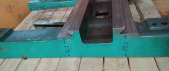
- Bed. A rigid base is used to accurately position all nodes relative to each other. Quite a lot of attention is paid to the accuracy of the positioning of all elements.
- Headstock. To transmit rotation, a pulley is installed connected to the spindle. The main rotation is created by an individual electric motor. It was decided to eliminate the possibility of engine overheating in case of jamming of the mechanism using a V-belt drive. It is also used to change the number of revolutions. The spindle head is characterized by the presence of six gear shift speeds. In this case, the adjustment occurs due to the movement of the gear block. The presence of a large number of rubbing elements determines that a lubricant supply pump is installed to reduce wear. It also operates from the main drive.
- Caliper. Longitudinal and transverse movement of the caliper is carried out mechanically. To do this, a gearbox and an apron with a roller were installed. If necessary, a manual drive, represented by gears and a flywheel, can be used. There is also a quick feed, which is needed to change the position of the caliper.
- Tailstock. It is used to significantly improve cutting accuracy. When installing the required equipment, you can fix the workpiece at the second end, thereby reducing vibration.
- Sleds for moving moving elements. They are manufactured using stainless steel with high strength and reliability. In order for the movement of the main elements to occur without resistance, lubricating fluid is supplied to the slide.
- The control units are represented by various handles and keys, as well as dials.
Stainless steel and cast iron are used in production. The screw-cutting lathe 1E61 has a standard layout, the use of high-quality materials and the precise positioning of all elements has increased the cutting accuracy. The guitar's gears are hidden in the headstock. In addition, the 1E61M screw-cutting lathe has built-in overload protection, which significantly extends the service life of the equipment. The following technical parameters of the 1E61M model must be taken into account:
- Moving the caliper.
- Dimensions.
- Application area.
- Possible operating modes.
Download the passport (operating instructions) of the 1E61VM lathe
The technical characteristics of the models under consideration are practically the same. By taking into account the basic parameters, it is possible to determine what type of processing can be carried out.
Rules for setting up equipment and operation, passport
Stable operation of the machine depends on the accuracy of the preliminary settings. For a rigid type of cross-slide connection, you will need to adjust the slide wedge. The action algorithm is as follows:
- Loosen the screw a little.
- Tighten the wedge with another screw so that the movement of the slide remains smooth.
- Tighten the first screw as far as possible.
Be sure to periodically check the tension of the V-belts. They stretch out over time and this affects the safety of the turning mechanism.
The lathe's passport can be downloaded for free from the link - Screw-cutting lathe lathe 1E61M passport
Algorithm for adjusting V-belts:
- remove the front cabinet from all covers;
- tighten the slide using a special technique, running a special screw along the grooves to select the optimal tension level;
- secure the result with nuts.
Then you should adjust the spindle belts of the turning equipment.
Characteristics of the 1M61 lathe
Below are several tables with the parameters of the unit in question.
Dimensions of processed workpieces:
| Name | Unit | Options | Notes |
| Accuracy category (GOST) | – | N | _ |
| Maximum diameter of workpiece | mm | 320 | Above the bed |
| Similar indicator | mm | 160 | Above the caliper |
| Maximum product length | mm | 710 | 100 on new modifications |
| Cutter height | mm | 25 | – |
| Flange spindle edges | – | 6K | According to GOST 12593-72 |
| Diameter of the rod that fits into the spindle hole | mm | 32 | – |
| Center of headstock assembly | mm | – | GOST 13214-67 |
| Number of gears (longitudinal and transverse) | PC | 17 | – |
Cutting threads:
| Metric | Modular | Pitch | Inch |
| 13 mm with step limit 0.5-6.0 units | 10 mm in increments of 0.25 to 3 mm | 16 positions plus pitch from 7 to 96 mm | 16 options with thread count per inch 3.5/48 |
Spindle and additional elements of the 1M61 lathe:
| Spindle | Cutting slide |
| Direct rotation - 24 speeds | Maximum movement – 120 mm |
| Reverse speed – 24 gears | Maximum rotation angle – -60/+45 degrees |
| Intensity of forward and reverse rotation – from 12.5 to 1600 rpm | The price of one division is one degree |
| Prodeli in a longitudinal configuration - 0.08-1.2 mm/rev | The indicator on the limb is 0.05 mm |
| A similar indicator in the transverse length is 0.04-0.95 mm/rev | – |
| Hole diameter – 35 mm | – |
| Braking – available | – |
Overall dimensions: length/width/height – 2.055/1.095/1.45 m. Weight – 1.26 tons.
Maintenance and repair
If repairs or some maintenance work is necessary, you need to properly disassemble the machine:
- First of all, disconnect the unit from the power supply.
- Disconnect the pressure and drain pipes from the oil system.
- Before removing the spindle head, disconnect the V-belts.
In automatic mode, the screw-cutting lathe is lubricated. The unit is equipped with a centrifugal vertical pump for this purpose. The 1E61M lathe was produced for small private workshops, for small-scale enterprises, as well as for use in household workshops. It is characterized by increased processing accuracy and relative safety of operations.