Differences from an inverter device
Such equipment differs from transformer equipment in the following characteristics:
- Light weight. If the mass of the transformer is about 35 kg, then for the inverter it does not exceed 15 kg. This makes it easy to move the device during operation.
- No transformer in the design. This eliminates energy consumption for heating the windings and magnetization reversal of the magnetic circuit. The efficiency increases. When using an electrode with a diameter of 3 mm, energy consumption does not exceed 4 kW. Under the same conditions, this parameter for the transformer is 7 kW.
- Possibility of obtaining current with any current-voltage indicators. Inverter-type devices are used for welding all metals. They work with stainless, alloy steel, copper, aluminum.
- Operating modes. The inverter does not require frequent interruptions for cooling.
- Possibility of fine tuning. The welder selects current and voltage values over a wide range. Using an inverter you can cook in different spatial positions. This produces the least amount of molten metal splashes.
Trigger device
The starting device includes a magnetic circuit, two windings and terminals. Switches change the voltage and the total number of windings connected to the rectifier. A regulator assembled on the basis of semiconductors (thyristors) is installed in the primary circuit. The second winding, connected to the rectifier bridge, provides two levels of variable voltage.
Transformer trigger device
To operate the starting device, a voltage of 220 V is required. The current ranges from 0 to 120 A, and the voltage reaches 70. In the case of self-manufacturing of the device, a core transformer is taken as a basis, 230 turns are wound on its first winding, 32 on the second. Control panel semiconductors are mounted above the inductor. Forced ventilation is used to cool the entire system.
Magnetic circuit design
The key parts of the magnetic circuit are plates or sheets made of electromagnetic steel. Structural parts include fasteners, housing, etc. Magnetic cores of welding transformers are divided into rod and armored. In rod-type devices, all segments of the magnetic circuit have the same cross-section. In armor-type magnetic cores, only the middle rod on which the windings are installed has a full cross-section.
Types of transformer magnetic cores
The cross-sections of the remaining sections of the magnetic circuit are almost two times smaller. The magnetic flux is closed along them. In sections of the magnetic circuit having a T-shape, each has its own cross-section. Moreover, its size is three times smaller than the rod itself. For each section, a third part of the flow is closed. The plates included in the packages are coated with a special compound called oxide insulation. Operating principle of a welding transformer Welding equipment operates according to the following algorithm:
- Power is supplied to the first winding. It generates a magnetic flux that closes on the core.
- The power is then sent to the second winding.
- The magnetic core, which is assembled from ferromagnets, generates a constant magnetic field. The inducing flow produces an emf.
- The difference in the number of turns allows the current to fluctuate with the parameters required for welding. The same indicators are taken into account when calculating welding equipment.
There is a relationship between the number of turns on the second coil and the output voltage. That is, to increase the current, the number of turns must be increased. But since the welding transformer is a step-down type, the number of turns on the second winding will be lower than on the first. The design and principle of operation of the welding transformer provides adjustment of the current value. This is achieved by reducing or increasing the space between the coils. To achieve this, welding equipment contains moving components. The distance between the windings changes the resistance and this makes it possible to select exactly the current needed for welding.
Idling
Welding equipment operates in two modes - working and idle. During welding, the second winding is closed between the working tool and the workpiece. The current melts the edges of the workpieces and the result is a reliable connection of the parts. After the welder finishes the work, the circuit is interrupted and the transformer switches to idle. EMF in the first winding appears due to the presence of:
- magnetic flux;
- its dispersion.
Transformer no-load
These forces bud from the direction of the flow in the magnetic circuit and are closed between the coils in the air. It is these forces that are the basis of idle work. Idle operation should not pose a danger to the welder and surrounding people. That is, it should not be more than 46 V. But certain models of welding equipment have higher values, for example, 60 - 70 V. In this case, an idle speed limiter is installed in the design of the welding device. Its response speed does not exceed one second from the moment the circuit breaks and the end of operation. For additional protection of the welder, the transformer housing must be grounded.
This allows the voltage that may appear on the housing as a result of damage to the insulation to go into the ground without causing any harm to the welder.
Welding transformer design
Such a device includes several components that create an electric arc capable of melting steel. The components change the parameters of the currents coming from the network.
The unit lowers the voltage, increasing the amperage.
Welding of metals becomes possible thanks to the components included in the design of the device:
- magnetic circuit;
- primary winding of insulated cable;
- screw;
- moving secondary winding made of bare wire;
- running nut;
- handle that rotates the screw;
- clamps for fixing cables;
- cooling system.
We recommend reading: What types of welding devices are there?
The magnetic circuit does not affect the current parameters, it only forms a magnetic field. For this, a set of steel plates coated with an oxide composition is used. Some transformers include additional components that improve the performance of the equipment.
Welding rectifiers
Equipment that converts alternating voltage coming from the power supply into direct voltage, necessary for performing electric welding work. In practice, several rectifier circuits are used, which implement different methods for obtaining output voltage and current parameters. Various methods are used to adjust the current parameters and current-voltage characteristics.
Welding rectifiers
These methods include: Changing transformer settings, using a choke, tuning using semiconductors (thyristors and transistors). In the simplest devices, a transformer is used to regulate the current, and diode circuits are used to rectify it. The power part of such equipment includes a transformer, rectifier, and inductor.
Advantages and disadvantages of welding rectifiers
The main advantage of rectifiers, when compared with transformers, is that direct current is used for welding. This ensures the quality of ignition and maintenance of arc parameters and this, accordingly, leads to the quality of the weld. The use of a rectifier allows you to weld not only ordinary steels, but also process stainless steel and non-ferrous metals. In addition, it must be taken into account that welding using a rectifier provides a small amount of spatter.
In fact, the described advantages give a clear answer to the question - which device to choose a transformer or rectifier, but of course we must not forget the cost of this equipment. Rectifiers also have certain disadvantages - large weight of the structure, loss of power, voltage drop in the network during welding work. By the way, everything said fully applies to transformers.
Types and classification of devices
Welding units are classified according to the following characteristics:
- Size and weight. The devices can be compact, portable or stationary, moved using wheels or a hoist (suspended lifting device).
- Open circuit voltage of the welding transformer. In different models of devices, this parameter ranges from 48 to 70 V.
- Maximum current strength. For industrial models this parameter reaches 1000 A, for household models – 50-400 A.
- Voltage of current consumption, number of phases. There are single-phase or three-phase types.
- The nature of the presentation. The device can generate current continuously or pulsed.
- Diameter of connected electrodes.
The principle of working with characteristics
Devices for transformer welding function as follows:
- Current from the electrical network enters the primary winding. Here a magnetic flux appears, directed towards the core.
- The voltage is transmitted to the secondary winding.
- The ferromagnetic core generates a magnetic field. Electromotive forces of a variable nature are generated in 2 windings.
- The difference in the number of turns of the coils helps to change the current parameters to the volt-ampere indicators necessary for welding. Based on these values, the characteristics of the transformer unit are calculated.
The number of turns of the winding is directly related to the output voltage. A secondary coil wound in larger quantities increases the current strength. A transformer welding machine is a step-down device. The number of turns of the primary winding in it is greater than the secondary. You can regulate the output current by changing the gap between the coils.
Idling
The operating principle of the welding transformer includes 2 modes: idle and with load. During welding, the secondary coil creates a short circuit between the workpiece and the electrode. A powerful arc melts the material, forming a seam. After welding is completed, the secondary circuit is broken. The device starts to idle.
We recommend reading Features of setting up the Chameleon welding helmet
This mode of operation must be safe for the user. The maximum voltage value is 48 V. If the value exceeds the permissible values, the automatic limiter is activated. Grounding the unit body provides additional protection for the welder from electric shock.
Text of the book “Welding works. Electric arc. Gas. Cold. Termite. Contact welding"
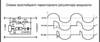
Simple electronic welding current controller
The electrical circuit diagram of this simple device is shown in Fig. 56. Its main elements - thyristors VS1 and VS2 - are connected in counter-parallel to each other. They are opened alternately by current pulses generated by transistors VT1 and VT2.
When the regulator is connected to the network, both thyristors are closed, capacitors C1 and C2 begin to charge through the variable resistor R7. As soon as the voltage on one of the capacitors reaches the avalanche breakdown value of the transistor, the latter opens and the discharge current of the capacitor connected to it flows through it. This leads to the opening of the corresponding thyristor, which connects the welding machine to the network. After the start of the next half-cycle of the alternating current, the thyristor closes and a new cycle of charging the capacitors begins, but in reverse polarity. Now the second transistor opens, and the second thyristor reconnects the welding machine to the network. By changing the resistance of the variable resistor R7, you can regulate the moment the thyristors are turned on during a half-cycle, which will lead to a change in the welding current.
The regulator is assembled using thyristors designed for direct current of more than 40 A and voltage of at least 400 V, type T131-40-4, T132-50-4, T141-63-4, etc. Transistors VT1 and VT2 are low-power, high-frequency type P416 , P422—P423, GT 308, GT320, GT338. Capacitors - type MBM, K73 or other similar ones for a voltage of at least 40 V. Resistors - type MLT-0.5. Variable resistor R7, due to the galvanic connection of the network with the elements of the regulator, must have a plastic axis. A correctly assembled regulator requires virtually no adjustment. To increase the limits and smoothness of welding current regulation, it is recommended to set the value of the variable resistor experimentally.
Rice. 56. Diagram of a simple welding current control unit
The circuit is assembled in a separate case made of insulating material with ventilation holes and is connected to the break in the core of the ST network wire.
It must be remembered that the shape of the welding current in devices with thyristor control differs from sinusoidal and the effective value of the current, which characterizes the heat losses in the windings of the control thyristor, is greater than the average value of the welding current. In general, this leads to the need to increase the cross-section of the transformer winding wires, use more powerful thyristors and install them on larger radiators. If you use the device with an existing transformer with an insufficient cross-section of winding wires, it is necessary to strictly maintain the operating mode - intermittent and short-term, especially when working at high welding currents. Heating occurs especially quickly in metal cutting mode, so in this case the device must “rest” more often and longer. You can further increase the turn-on time of the transformer by installing a forced cooling fan on its housing.
The disadvantage of this regulator is that igniting the welding arc at low currents requires some skill at the initial stage.
However, this drawback does not appear when operating at medium and high currents. Therefore, it can be recommended to light the arc at high or medium currents and, without interrupting its combustion, use the regulator to reduce the welding current to the required level. Welding transformer with electronic current regulation
This transformer, powered by a single-phase alternating current network with a voltage of 220 V, is designed for electric arc welding of products made of structural steel with electrodes with a diameter of 2–5 mm. The electronic current regulator allows you to smoothly change the welding current from 20 to 200 A, which makes it possible to weld parts of various thicknesses. One of the advantages of the design is the absence of expensive and scarce parts.
As follows from the circuit diagram (Fig. 57), this device consists of the power transformer Tr1 itself, control thyristors VS1 and VS2 connected to the circuit of power winding II, and an electronic control unit that generates control pulses. Additional winding III stabilizes the arc and makes it possible to improve the process of its formation at the initial moment of welding. Winding IV powers the electronic current control unit.
Transformer Tr1 is made on the basis of the stator core of an AC asynchronous motor with a power of 15, 18.5 or 22 kW. Its primary winding I contains 220 turns of PEV-2 (copper) or APSO (aluminum) wire ∅2.5 mm. The wire is wound evenly over the entire cross-section of the magnetic circuit.
Rice. 57. Schematic diagram of a welding transformer
If there is no wire of the required diameter, the winding can be made with two wires, and their total cross-section should be 5 mm2. The no-load current of the primary winding should not exceed 0.3–0.5 A.
Secondary winding II is made of wire with a cross-section of 35 mm2, it contains 60 turns. The wire can be a copper or aluminum busbar with reliable insulation. Next to winding II on the magnetic core, winding III is placed, which also contains 60 turns of wire, but thinner - grade PEV-2 ∅2.5 mm. Winding IV contains 40 turns of PEV-2 wire ∅0.7 mm with a tap from the middle. With the previously indicated no-load current, the voltage on windings II and III should be 60 V, and on winding IV - 40 V.
The electronic current control unit is based on a circuit of a similar industrial device, namely the TS-200 transformer. The regulator's wiring diagram is printed or mounted, but in any case the regulator must be enclosed in its own reliable housing.
Transformer Tr2 is wound on a magnetic core Ш16 with a set thickness of 16 mm. Its winding I contains 140 turns of PEV-2 wire ∅0.5 mm, winding II contains 70 turns of PEV-2 wire ∅0.1 mm, windings III and IV each contain 90 turns of PEV-2 wire ∅0.5 mm.
Resistors R1—R9 – type MLT-0.5; R10, R11 – MLT-2 type; R12 – type SP2-6A.
Capacitors C1 and SZ - type K-50-6; C2 and C4 – type K73. Thyristors VS1 and VS2 are installed on heat sinks with a surface area of 1000 mm2 each.
A unit assembled without errors and from serviceable parts does not require adjustment.
One of the options for the design of the ST is shown in Fig. 58. Transformer Tr1 is mounted on a round base ∅400 mm made of textolite 10 mm thick or plywood 15 mm thick. Two blocks of hard wood with a cross-section of 30 × 30 mm and a length of 350 mm should be placed under the transformer to ensure air circulation and improve its cooling during operation. The transformer is secured to the base with an M12 coupling bolt of appropriate length. Radiators with thyristors are mounted on the top plate.
Rice. 58. Transformer wiring diagram:
1 – transformer winding; 2 – thyristor radiator; 3 – thyristor; 4 – top plate; 5 – block; 6 – carrying handles; 7 – housing of the adjustment unit; 8 – potentiometer (R12); 9 – terminal for connecting the welding cable; 10 – mounting bolt; 11 – bottom plate; 12 – bracket for winding the network cable; 13 – network cable
The base has two handles for carrying the transformer, made of 1/2˝ steel pipe. Two textolite plates 6 mm thick are attached to the same handles. One of them is equipped with a current control unit, a potentiometer R12, and also has terminals for connecting the welding cable (M12 bolts). The second plate has two brackets for winding the network cable after finishing work. Here you can also install a circuit breaker rated for a current of at least 25 A.
The transformer allows the following operating mode: operation - 1 hour, break - 10 minutes. Welding is carried out using E-5RA UONI-13/55-2.5 UD-1 electrodes of the required diameter.
DC Welding Sources
All welding sources discussed previously are alternating current sources.
They are quite simple to manufacture and reliable in operation. However, the use of direct current allows in many cases to improve the quality of welding, which was discussed in the first section of this book. In addition, some types of electrodes, such as those for stainless steel, require only direct current, while electrodes designed for alternating current operate normally on direct current. There is not even an annoying (and even harmful effect on people) crackling noise when welding with direct current. And all because the main feature inherent in AC welding machines is missing - intermittent arc burning when the supply voltage sinusoid flows through zero. Simple rectifiers
DC welding machines
consist of an already well-known welding transformer and a device that converts alternating current into direct current. Moreover, any ST can be converted, so we will not consider their designs any further. Let's deal with what allows us to obtain a constant (as well as adjustable) welding current.
The easiest way to get a DC welding machine is to connect a bridge rectifier to the terminals of the secondary winding of the CT (Fig. 59).
The rectifier bridge in amateur circuits is most often made on the basis of powerful diodes such as D161-200, D161-320, V200. These diodes are of impressive size, and their housing is mounted on aluminum radiators. Moreover, the diode body, and therefore the large radiator, is under voltage, so diodes with radiators must be mounted so as not to touch the conductive parts of the device body. In this case, two groups of oppositely polarized diodes should be used: one pair with a cathode on the threaded terminal and a pair with an anode on the threaded terminal[23] 23
In the designations of power rectifier diodes produced in accordance with GOST-20859, a special symbol “X” has been introduced to mark diodes with reverse polarity. For example, D161-200X-8. This is deciphered as follows: power diode, rectifier, first modification, with a pin housing design and a flexible lead, hexagon wrench size 32 mm, maximum rectified current 200 A, maximum repeating reverse voltage 800 V, reverse polarity (“—” - the cathode is the base ). A diode of the same type, but without the “X” symbol in the marking: D161-200-8 – the same, straight polarity (“+” – the anode is the base). The vast majority of power rectifier diodes are produced in both direct and reverse polarity.
[Close]. Thanks to this feature, pairs of radiators in each of the two groups of diodes do not need to be isolated from each other. But the radiators of the groups should under no circumstances have contact with each other. As shown in Fig. 60, pairs of radiators are connected to each other by ∅8 mm studs. The threaded ends of the same studs are also the output terminals of the rectifier: “+” and “-”. During assembly, an insulating rubber gasket 5 mm thick is installed between the two groups of radiators.
Rice. 59. Bridge rectifier as part of a simple welding machine:
SA1 – mains power switch; FU1 – fuse 10–16 A; T1 – welding transformer; U2 – output alternating voltage of the welding transformer; VD1—VD4 – rectifier bridge (diodes V200, VD161, etc.)
After installation on the SP housing, it is better to close the upper part of the rectifier - the flexible leads of the diodes - with a U-shaped cover. However, such a rectifier can also be assembled as an independent product, connecting to a transformer only when DC welding is needed. Then it should be enclosed in its own enclosure. This straightener weighs no more than 5 kg.
If your welding machine does not develop high power and welding work is planned occasionally, it is not necessary to buy powerful, heavy and expensive diodes. You can purchase imported diode bridges integrated in one housing. The size of one such integrated rectifier is comparable to the size of a matchbox or one B-200 diode without a radiator. It can withstand a maximum current of 30–50 A. If such bridges are connected in parallel (Fig. 61), then together they can withstand higher currents. Strictly speaking, the total current of the combined rectifier is not equal to the sum of the maximum currents of the diode bridges included in it. After all, they cannot have absolutely identical parameters, which means that each passes through itself currents that differ in magnitude. Therefore, breakdown of the diodes of the assembly cannot be ruled out during the shock current pulse that occurs when the arc is ignited.
Rice. 60. Design of the rectifier unit:
1 – AC voltage terminals; 2 – slab (plywood or textolite S = 10 mm); 3 – diodes; 4 – cooling radiators; 5 – insulating gasket (rubber, S = 5 mm); 6 – M8 tie rods (DC terminals)
However, if you assemble this circuit with some power reserve, taking into account the short-circuit current, you can achieve not only significant savings, but also more compact sizes than in the case of the B-200 and other powerful diodes. The fact is that the housings of the diode bridges are not energized. They can be attached to one common radiator and placed in any convenient place inside the body of the welding machine.
For such a composite rectifier, 4–6 integrated diode bridges are usually used, always of the same brand. As practice shows, they do not get very hot and can even withstand short-term overloads without problems, despite the fact that the welding machine generally operates in a short-term mode. For example, by connecting in parallel six KBPC5010 diode assemblies, each of which is designed for a current of 50 A, we get one diode bridge, designed for a current of 300 A. For cooling, an aluminum radiator with an area of approximately 800 cm2 is suitable, on which the assemblies are evenly placed and secured with M6 bolts, under which have holes in the center of the body.
To improve heat transfer, it is advisable to use heat-conducting paste KPT-8. After this, the circuit is soldered with a copper bus with a cross-section of 10 mm2, and to connect the entire rectifier to the current source and for the output of the welding current - 20 mm2. Don't forget to varnish all soldering areas.
Rice. 61. Diagram of a composite rectifier bridge consisting of four diode assemblies
The radiator of such a diode bridge with a welding current of 100 A in intensive mode (continuous operation with a ∅3 mm electrode for 10 minutes) should heat up to a temperature no higher than 50–60 °C.
If you plan to use more powerful currents, you can increase the number of assemblies. In addition, the rectifier will not be damaged by blowing it with a fan. If forced cooling is used for CT, then it makes sense to place the rectifier radiator so that it is also in the air flow.
Be sure to solder the busbars to the terminals of the diode bridges. If you connect bridges using terminals only, the ends of the bridge leads will get very hot.
It should be noted right away that equipping the ST with a diode bridge does not yet allow us to consider the welding machine complete. The fact is that there is an inevitable voltage drop across the diode bridges, so at the output of the DC power supply the voltage will be somewhere 4–5 V less than the open-circuit voltage of the transformer. In this case, the output voltage will not be strictly constant - its shape will be pulsating (Fig. 62, b), and the effective value of the constant pulsating voltage is √2 times less than the voltage of the peaks of the maximum amplitude of the alternating current. Because of this, it would be necessary to maintain a deliberately high voltage on the secondary winding, reaching up to 80 V[24] 24
The voltage at the output of the welding source should not exceed 80 V according to electrical safety requirements in accordance with GOST 95-77E.
[Close], although 25–36 V is sufficient to support arc combustion and metal deposition in the welding zone. Of course, the extra volts would be reflected in the form of an excessively large mass and dimensions of the SA, and increased energy consumption. By reducing the voltage transformed into the secondary circuit to 36 V, it is possible to lighten the weight of the device by 5–6 times and reduce its size to acceptable for carrying while simultaneously improving other performance characteristics. But how to light an arc with a low-voltage winding?
To smooth out voltage ripples, one of the rectifier terminals is connected to the electrode holder through an inductor (Fig. 62, d[25]25
This shows the CA connection for welding thin sheet metal with “reverse” polarity: “+” on the electrode, “—” on the part being welded.
[Close]). It is a coil of 10–15 turns of a copper bus with a cross section of 25–35 mm2, wound on any core, for example from a magnetic starter.
But the radical solution to the problem was the introduction of a large capacitor into the secondary circuit of the diode bridge. As a result, the output voltage increases almost 1.5 times, and the SA characteristic also turns out to be steeply falling (Fig. 62, c).
Rice. 62. Smoothing of rectified current ripples:
a – alternating current at the ST output; b – pulsating voltage after the diode bridge; c – steeply falling characteristic of SA when smoothing pulsations with a capacitor; d – smoothing of pulsations with a throttle; d – smoothing of ripples with a capacitor
The initial increased voltage created by the capacitor facilitates ignition of the arc. And when the potential on the welding electrode drops to the voltage of the secondary winding of the transformer (operating point “A”), a process of stable arc burning will occur with metal deposition in the welding zone. To create such an “energy miracle”, a capacitor with a capacity of 5000-10,000 microfarads is required. In this case, it will be charged at idle to the maximum voltage amplitude level.
It is especially recommended to install a capacitor if the power source has a low output voltage (less than 40 V) and difficulties arise when igniting the welding arc.
In this case, it is better to connect the capacitor through a resistance of 0.5–1.5 Ohms (Fig. 62, e). The presence of a resistor is due to the fact that at the moment the arc is ignited, the end of the electrode touches the metal of the product, i.e., a short circuit. If there is no resistance in the capacitor circuit, then an instantaneous discharge of a large capacitor occurs; a high current pulse is accompanied by a loud click, and often by destruction of the tip of the electrode or its instant welding to the metal of the product. Working with such a source is very inconvenient; the crackling sound of the discharges gets on your nerves. An additional resistor limits the current, smoothes the discharge of the capacitor, making arc ignition easier and softer. Rectifier with voltage booster
And yet, lighting an arc at low voltage is not easy. For a low-power welding machine, this is the most difficult mode, since the secondary winding is short-circuited for a short time until the electrode is removed from the part. The problem can be solved in the following way: the no-load voltage is increased in advance by a voltage booster device, and after the arc is ignited, it is reduced to the optimal 30–40 V. The diagram of such a device is shown in Fig. 63, a.
Welding transformer T1 with diode rectifier VD1-VD4 is supplemented by another winding III, rectifier VD5-VD8, inductor L1 and switching diode VD9. Winding III is wound on a separate frame and is located next to the coil containing the network and main windings I and II, respectively.
The main secondary winding II is designed for a voltage of 30–40 V and a current of 100–120 A. It provides the operating welding current in the arc. The additional secondary winding III is designed for a voltage of 12–14 V at a current of 10 A. It is this that generates the boost voltage.
Until the electrode touches the welded parts, the voltage on it is equal to the sum of the rectified voltage values of both windings, since the switching diode VD9 turns out to be closed by the output voltage of the bridge VD5-VD8, and both bridges are connected in series. The voltage at the electrode is 42–54 V.
When the electrode touches the part, the VD9 diode opens, the voltage on it decreases to 1.5 V, providing welding current through the ignited arc. Since welding current does not flow through diodes VD5-VD8 and inductor L1, ten-amp diodes are sufficient for this bridge, and the inductor can be wound on any magnetic core with a cross-section of 10–12 cm2. The winding is performed with PEV-2 wire ∅1.6–1.8 mm until the window is filled. When assembling the magnetic circuit, it is necessary to provide a non-magnetic gap between its parts by inserting a gasket made of pressed wood with a thickness of 0.5–1 mm.
Instead of KD242B, you can use diodes D305, D214, KD213A, KD213V, KD2999A - KD2999V. They must be installed on plate heat sinks with dimensions of 100 × 100 × 5 mm. Instead of VK2-200, diodes D161-250, D161-320 are suitable. These diodes are best mounted on finned or needle heat sinks.
Structurally, the voltage booster device can also be made in the form of an attachment to a ST converted to direct current. The diagram of such an attachment is shown in Fig. 63, b. It uses a TS-270 network transformer from old tube TVs with its “native” network winding. The secondary winding of 12 V at a current of up to 15 A must be wound independently. It is advisable to provide 13, 14 and 15 V terminals for this winding so that the console can be used for other purposes, in particular for charging batteries. Switching diode VD5 is included in the set-top box. Throttle L1 is the same as above.
Rice. 63. Voltage booster circuits for reliable ignition of the welding arc:
a – with additional winding ST; b – attachment to DC SA; c – economical scheme
If you change the circuit a little more, you can reduce the number of diodes needed, and therefore the bulky heat sinks for them. This option is shown in Fig. 63, v. The operation of this unit is similar to that described above, the only difference is that the role of switching is performed by two diodes VD1, VD3 of the rectifier bridge of the device. They open alternately for half the period of the mains voltage, when the arc is not yet ignited, and closed when the arc is lit.
Modification schemes
Changes are often made to the design of a standard device to help improve performance.
With shunt
The dissipation of the magnetic field is facilitated by a change in the spatial position of the components of the magnetic circuit.
When steel elements are displaced, the resistance of the flow through the air increases.
When the shunt is fully inserted, the parameter begins to depend on the distance between the part and the components of the magnetic circuit. Devices with this principle of operation are intended for use in industrial environments.
With winding in sections
This welding machine design is considered obsolete. Previously, this equipment was used in domestic and industrial settings. There are several options for choosing the number of turns in the primary and secondary windings.
Thyristor devices
To change the voltage and current, a phase shift of thyristors is used. When assembling a single-phase device, 2 parts are used, installed opposite each other. Thyristors are adjusted symmetrically and synchronously.
In semiconductor transformers, these elements are placed on the primary winding, which is explained by the following reasons:
- The strength of the secondary current in such devices is higher than in thyristors.
- When installing the latter on the primary coil, the efficiency increases. This is due to the reduction in voltage losses.
Calculation
It was already mentioned earlier that a welding transformer consists of a core, a primary and secondary winding. It is these nodes that determine the main operating parameters of the device.
It is necessary to decide in advance what the voltage on the windings, rated current, etc. should be. Based on these values, the windings, core and wire cross-section should be calculated.
In the calculation it is necessary to use such quantities as:
- mains voltage, which is the voltage of the primary winding U1;
- voltage of the secondary winding U2, the value of which should not be less than eighty volts;
- rated current strength of the secondary winding I, determined based on the thickness of the metal and electrodes with which to work;
- core section Sc, the area of which determines the reliability of the device;
- the core window area So is selected based on the calculation of good magnetic dissipation, removal of excess heat and convenience of wire winding;
- Current density A/mm2 is an important parameter that determines electrical losses in the windings.
To better understand the specifics of calculating transformer parameters, we should consider this entire process with an example. Let us assume that the following data are known: U1=220 V, U2=60 V, I= 180 A, Sc=45 cm2, So=100 cm2, and current density 3 A/mm2.
First of all, the power should be determined: P = 1.5*Sс*So = 1.5*45*100 = 6750 W or 6.75 kW.
Then the required number of turns in the primary and secondary windings is set. This value is determined from the number of turns per volt: K = 50/Sс = 50/45 = 1.11; and maximum current on the primary winding: Imax = P/U = 6750/220 = 30.7 A.
After the values of these parameters are obtained, the number of turns on the secondary winding can be determined: W2 = U2*K = 60*1.11 = 67 turns.
The calculation of turns in the primary winding is calculated using another formula, which will be indicated below.
Often, if it is necessary to calculate a toroidal transformer, the stages of current regulation are determined. This is necessary to output the wire on a certain turn. This characteristic can be determined using the formula: W1st = (220*W2)/Ust.
But first you need to set the voltage of each stage. This can be done based on the simple ratio U=P/I.
Design features of the welding transformer.
For example, you need to make four stages at 90, 100, 130 and 160 amperes. The power of the device is 6750 watts. Using the above ratio, we get: 75, 67.5, 52, 42.2 volts. The data is then plugged into the expression for the steps.
As a result, we get the following values: 197, 219, 284, 350 turns. Another 5 percent should be added to the last value. As a result, the number of turns will be 385.
Ultimately, you need to determine the cross-section of the wire on the windings. To obtain this value, the maximum winding current must be divided by the current density.
The above calculation is quite simple. It will not challenge any master. However, sometimes you don’t want to waste time even on such simple things. There is also always the possibility that an automatic mistake or typo may be made in some action, which will lead to serious consequences.
An online calculator will help you protect yourself and save time, allowing you to make all the calculations described above automatically.
After all the calculations have been made and if you have a diagram, you can begin assembling the device. The work cannot be called difficult, but it will require a certain perseverance. This is due to the need to clearly count the number of turns.
It was already mentioned above about the high popularity of the toroidal version of the device, but further we will consider the case of a transformer with a U-shaped core. This modification is more simple, which is why it was chosen.
First of all, it is necessary to make frames for the windings. Textolite slabs can be used for these purposes. This material is not difficult to find, as it is widely used in the creation of circuit boards. We assemble frames from them and insulate them with heat-resistant insulation. Then we make the winding.
After a layer has been laid, it must be insulated and only after that proceed to laying the next one. Upon completion of this process, copper bolts are fixed at the ends of the bends.
After the winding is formed, the magnetic circuit is assembled. The material used is iron, created specifically for this purpose. Metal is characterized by certain values of magnetic induction, and the wrong grade of steel can ruin everything.
The metal core plates can be removed from older units or purchased separately. The plates themselves are about one millimeter thick, and assembling the entire core requires only patiently connecting all the plates into a single whole. Upon completion, all windings should be checked for errors with a tester.
A high-quality homemade transformer may not work the first time. This may be due to various errors associated with incorrect calculations and lack of practice in assembling such devices.
While the calculation process can be significantly simplified using an online calculator, experience can only be gained through trial and error. Over time, after several attempts, creating a high-quality device with your own hands will no longer be difficult.
Advantages and disadvantages
The positive qualities of transformer equipment include:
- High efficiency, ease of operation and maintenance. Repairing the device does not involve large expenses, which allows it to be used at home.
- Low cost.
The disadvantages include:
- Arc instability. This is due to the AC parameters. To work with such devices, specialized electrodes are used.
- Changes in output voltage, which negatively affect the quality of the weld.
- Inability to use for joining parts made of non-ferrous metals or stainless steel.
- Dimensions and heavy weight, causing difficulties when moving.
We recommend reading: Do-it-yourself reliable plasma cutter. Instructions
The role of the transformer in welding
AC welding transformers are used in manual arc welding using stick electrodes, in mechanized welding using flux, and in argon arc welding for joining parts made of aluminum alloys.
The purpose of the welding transformer is to generate the voltage required for welding, certain constant external characteristics and to regulate the welding current.
The requirements for external parameters are determined based on the following indicators:
- type of electrode - it can be a melting or non-melting rod;
- the nature of the working environment - open arc, submerged arc, in protective gas;
- degree of automation of the welding process - manual, automatic, semi-automatic;
- The method of regulating the combustion mechanism is self-regulation, automatic.
Manual arc welding with coated rods, argon arc welding with a non-consumable tungsten electrode, mechanized submerged arc welding on automatic machines with control of the filler wire feed speed depending on the arc voltage - methods of joining metal parts in which a falling current-voltage characteristic is used.
Types of welding transformers.
A falling current-voltage characteristic implies operation of the device in welding current regulator mode. Based on technological and economic considerations, smooth step control is used.
This type of control involves two or more stages of regulation, combined with a smooth change in the current value in each stage.
The rigid current-voltage characteristic is used in automatic submerged arc welding at a constant filler wire feed speed, regardless of arc voltage.
The power supply in this case works as a voltage regulator.
The voltage change can be:
- smooth;
- stepped;
- mixed.
The amount of welding current depends on the speed at which the electrode wire is fed. The power source, in turn, sets the arc voltage and ensures self-regulation of its length.
Depending on the number of phases there are:
- Single-phase welding transformer - a model that operates only at a voltage of 220 V. Designed for domestic needs.
- Three-phase transformer - operates at a network voltage of 380 V. Such models are capable of providing high current output, which makes it possible to connect metal parts of large thickness.
Features of choosing a welding transformer
When deciding which device to buy, take into account the following criteria:
- Types of metals to be welded, parameters of future seams. To work with steel, manual equipment with direct or alternating current is sufficient. The operational qualities of the transformer allow you to weld products from any ferrous metals.
- Current strength. In domestic conditions, a unit producing 200 A is sufficient.
- Operating principle. Semi-automatic devices are reliable and easy to use, but they are expensive. When using manual units, the welder will have to independently control all parameters.
- Reliability of the manufacturer.
Transformer diagram and calculation
During the calculation, the following parameters must be determined:
- Operational indicators: type of supply network, adjustment range, actual power, duration of continuous operation.
- Welding electrode dimensions.
- Conditions for continuous operation.
- Device efficiency.
Some of the listed parameters are interrelated, for example, phase and network voltage.
The welding current determines the functionality of the transformer, namely, the thickness of the metal being welded. In addition, with increasing current, the diameter of the wire in the windings, the mass of the unit and its dimensions increase, which is due to the need for more efficient cooling of the windings.
The relationships between the main operational characteristics of welding transformers are given below:
- When the thickness of the workpiece being processed is 1...2 mm, the nominal diameter of the electrode is 1.6 mm, and the recommended current value is no more than 50 A.
- When the thickness of the workpiece is 2...3 mm, the nominal diameter of the electrode is 2...2.5 mm, and the recommended current value is no more than 100 A.
- When the thickness of the workpiece being processed is 3...4 mm, the nominal diameter of the electrode is 3 mm, and the recommended current value is no more than 160 A.
- When the thickness of the workpiece is 4...6 mm, the nominal diameter of the electrode is 4 mm, and the recommended current value is no more than 200 A.
- When the thickness of the workpiece is 6...8 mm, the nominal diameter of the electrode is 5 mm, and the recommended current value is no more than 250 A.
- When the thickness of the workpiece is 10...24 mm, the nominal diameter of the electrode is 6...8 mm, and the recommended current value is no more than 320 A.
- When the thickness of the workpiece is more than 24 mm, the nominal diameter of the electrode is 8...10 mm, and the recommended current value is no more than 630 A.
A more detailed calculation of the parameters of a welding transformer is usually carried out when making the unit with your own hands.
What malfunctions can there be
When working with a welding transformer, the following problems often arise:
- No arcing, cooling fan failure to start. The main reason is a violation of the integrity of the power cable. It is less common to detect damage to other equipment components or activation of overheating protection.
- No welding arc when the fan is running. It is observed when there is a breakdown in communication between the internal components of the system.
- No electric arc when the warning light is on. This problem occurs when the protective mode is triggered.
- Formation of a large amount of splashes. The seam quality remains low. It is worth checking that the wires are connected correctly and changing the polarity.
Possible malfunctions and repairs
Welding equipment, like any technical device, can always fail. There are some signs that can help you identify problems that have occurred.
Possible faults
For example, when welding, the electrode constantly sticks. This may be caused by low voltage, incorrect current setting, incorrect electrode selection, or a number of other reasons. No arc can be caused by a broken cable, overheating of the welding equipment and many other reasons.
To repair a welding transformer, you must have certain knowledge, that is, you need the ability to read electrical circuit diagrams and the skill of performing electrical installation work. That is why it makes sense to contact a workshop for repair and maintenance if malfunctions occur.
How to mount the device yourself
The main part of a homemade unit is the core. It is made of transformer steel, which is quite difficult to buy. The resulting structure has the shape of a rectangle with a cross-section of more than 55 cm². When forming the primary and secondary coils, install the adjusting screw. It is used to move the movable winding.
The wire cross-section of the first coil must be more than 5 mm². To assemble the transformer, cables with heat-resistant insulation are used.
The secondary winding is formed from a copper conductor with a cross section of 30 mm². At the last stage, a textolite body is assembled, which serves to protect the welder from electric shock.